

Page 1
®
BLV Low Velocity
Unit Coolers
PRODUCT DATA &
INSTALLATION
B30-BL V-PDI-50
1073479-50
Bally
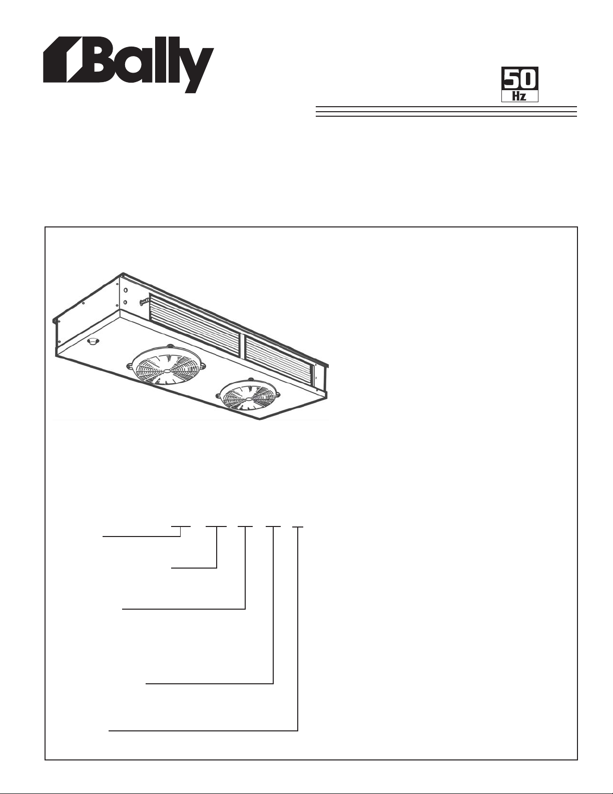
Low Velocity Unit Cooler
NOMENCLATURE
BLV 150 ED - SY B
Applications:
High T emperature
35 °F (2 °C) or Above Box T emperature and
Medium T emperature
28 °F to 34°F Box Temperature (-2 °C to 1 °C)
Defrost Types:
Air , Electric or Hot Gas Defrost
• Heavy gauge textured aluminum cabinet construction
resists scratches/corrosion and minimizes weight for
shipment, installation and service.
• High-efficiency PSC motors.
• Specially designed for quiet operation - ideal for
prep. rooms.
• Capacity up to 37,000 BTUH nominal.
• Dual refrigeration coils with two-way air distribution
reduces air velocities to minimize product dehydration.
• Reduced operating charge with 3/8” OD tubing
• Spacious end compartment allows for easy
component installation.
• Attractive and durable high - density poly propylene fan
guards.
• Hinged drain pan provides convenient access for
cleaning.
• Terminal board allows for easy electrical connections.
• Refrigerants R22, R404A, R507 and R134a.
• Options: - Factory mounted solenoid valve, TXV and
Thermostat.
- Fin material and special coatings.
- Other options available - consult factory .
Nominal Capacity @ 10 oF TD
150 x 100 = 15000 BTUH
Rated at 20 oF Evap. Temp.
Type of Defrost
AD = Air defrost
ED = Electric Defrost
HE = 3 Pipe Defrost, Electric Heated Drain Pan
RE = Reverse Cycle Defrost, Electric Heated Drain Pan
TE = Thermosaver Defrost, Electric Heated Drain Pan
Electrical Designation
SY = 100/1/50
S2 = 200-220/1/50
Unit Series
B = Second Generation
CONTENTS PAGE
Nomenclature.................................... Cover
Capacity Data ................................... 2
Electrical Data .................................. 3
Dimensional Data.............................. 4
Installation Clearances..................... 5
Wiring Diagrams............................... 6 - 10
TXV Selection.................................... 11
Distributor Nozzle Selection.............. 11
Installation Instructions...................... 12 - 13
Service Parts List............................... 14
Service Log....................................... 18
Warranty............................................ 19
Project Information............................ 19
“As Built” Service Parts List............... Back
Page 2
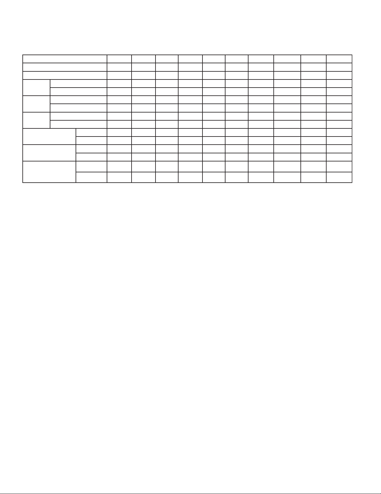
CAP ACITY DA T A
50Hz
ledoM.pmeThgiHDA060DA090DA021DA051DA081DA022DA072DA003DA043DA073
ledoMtsorfeDcirtcelEDE060DE090DE021DE051DE081DE022DE07
ledoMtsorfeDsaGtoH06
yticapaC*
yticapaC*
yticapaC*
riA
wolF
**egrahC
thgieW
‡
:ETON 05/3/022-002noetarepootdetrevnocdleifebnacsretaehtsorfeD
TTAW()3.6161()5.4242()6.2323()8.0404()9.8484()5.6295()4.3727()6.1808()1.9519()3.7699(
tnaregirfeR
teNtinU.dtS
)tnaregirfeRo/w(
F°02+@22R** C°6.6-( .diuqilfolluf%03liochtiw.T.S.S)
.D.TF°1@HUTB
.D.TF°01@HUTB
.D.TF°51@HUTB
MFC
)S/L()533()934()095()387()199()5901()6331()7651()3171()7981(
.BL
)GK()2.1()0.2()0.3()3.3()6.3()6.4()5.4()5.5()0.7()0.7(
.BL
)GK()14(84()36()27()001()701()711()321()721()231(
F°02+@22RhtiwdetaryticapaC* C°6.6-( ) .T.S.S
‡
05502800110831066102020842067203130043
).D.TC°55.0@STTAW()0.161()1.042()1.223()1.404()1.684()5.1
025508280401100831065610420204842006720821304043
).D.TC°55.5@S
0828024210656100702048420630306273004140296406015
).D.TC°33.8@STTAW()5.4242()7.6363()9.8484()2.1606()4.3727()7.9888()1.01901()4.22121()7.83731()9.05941(
01703905210661001202320382023303630204
6.24.45.63.70.82.010.010.213.513.51
09501931851022532552072082092
‡
09
‡
021
edocetairporppatresnidnaerutalcnemontsorfeDsaGtoHotrefeR
‡
051
‡
081
95()2.627()2.808()5.619()6.599(
2DE003DE043DE073
‡
022
‡
072
‡
003
‡
043
‡
073
- 2 -
Page 3
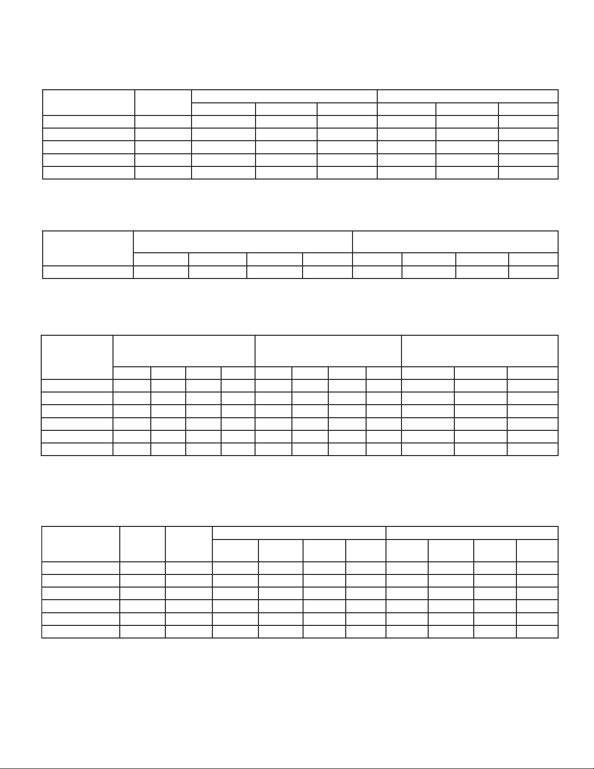
ELECTRICAL DATA
Air Defrost Models - 100/1/50 and 200-220/1/50
ledoM
090,060
1,021
05
072,022,081
043,003
073
irtcelE*
Electric Defrost Models - 100/1/50
ledoM
090,060
Electric Defrost Models - 200-220/1/50
ledoM
d
51,021
003
043
073
sliate
090,060#
0
072,022,081
aoLlluF=ALF
15.06.05102715.73.9515.46.551
20.11.15101927.218.51028.77.951
35.16.15105140.816.22521.118.3151
40.21.25105140.816.22521.118.3151
40.21.25101152.2
55.26.25101152.228.72036.310.7102
fo.oN
snaF
11.14.1515.06.051
22.25.2510.11.151
33.36.3515.16.151
44.47.4510.21.251
55.58.5515.26.251
ytitnauQALF*ACMPOMsttaWALF*ACMPOM
11.14.15102710.518.8102
ytitnauQALF*ACMPOMsttaWALF*ACMPOMALF*ACMPOM
ALF*ACMPOMALF*ACMPOM
MyticapmAtiucriCmuminiM=ACMspmAdaoLlluF=ALF
rotoMnaF
rotoMnaF
05/1/022-0026SedoClacirtcelE
50Hz
05/1/001YSedoClacirtcelE 05/1/022-0026SedoClacirtcelE
noitcetorPtnerruCrevOmumixaM=PO
yticapmatiucricmuminimhtiwecnadroccanidezisebotsigniriWlac
05/1/001YSedoClacirtcelE
noitcetorPtnerruCrevOmumixaM=POMyticapmAtiucriCmuminiM=ACMspmAdaoLlluF=ALF
apmatiucricmuminimhtiwecnadroccanidezisebotsigniriWlacirtcelE*
ytic
sretaeHtsorfeD
05/1/022-0026SedoClacirtcelE
28.72036.310.7102
noitcetorPtnerruCrevOmumixaM=POMyticapmAtiucriCmuminiM=ACMspmAd
yticapmatiucricmuminimhtiwecnadroccanidezisebotsigniriWlacirtcelE*
ataD
errucrevoretaehA51mumixamgnisurotcatnocretaehtsorfedtuohtiwetarepootderiwdleifebnacsledomesehT#
sretaeHtsorfeD
05/3/022-002
05/1/001YSedoClacirtcelE
-sretaehtsorfedrof
noetarepootdetrevnocdleif
rof9egapeeS.noitcetorptn
Hot Gas Defrost Models - 100/1/50 and 200-220/1/50
ledoM
090,060
051,021
072,022,081
003
043
073
*
fo.oN
snaF
10353.51.14.1513.25.06.051
20353.52.25.2513.20.11.151
30575.73.36.3513.35.16
40575.74.47.4513.30.21.251
40393.94.47.4510.40.21.251
50393.95.58.5510.45.26.251
naPniarD
retaeH
sttaW
retaeH
spmA
mAtiucriCmuminiM=ACMspmAdaoLlluF=ALF
naF
ALF
yticapmatiucricmuminimhtiwecnadroccanidezisebotsigniriWlacirtcelE
- 3 -
05/1/001YSedoClacirtcelE 05/1/022-0026SedoClacirtcelE
*ACMPOM
retaeH
spmA
noitcetorPtnerruCrevOmumixaM=POMyticap
naF
ALF
*ACMPOM
.151
Page 4
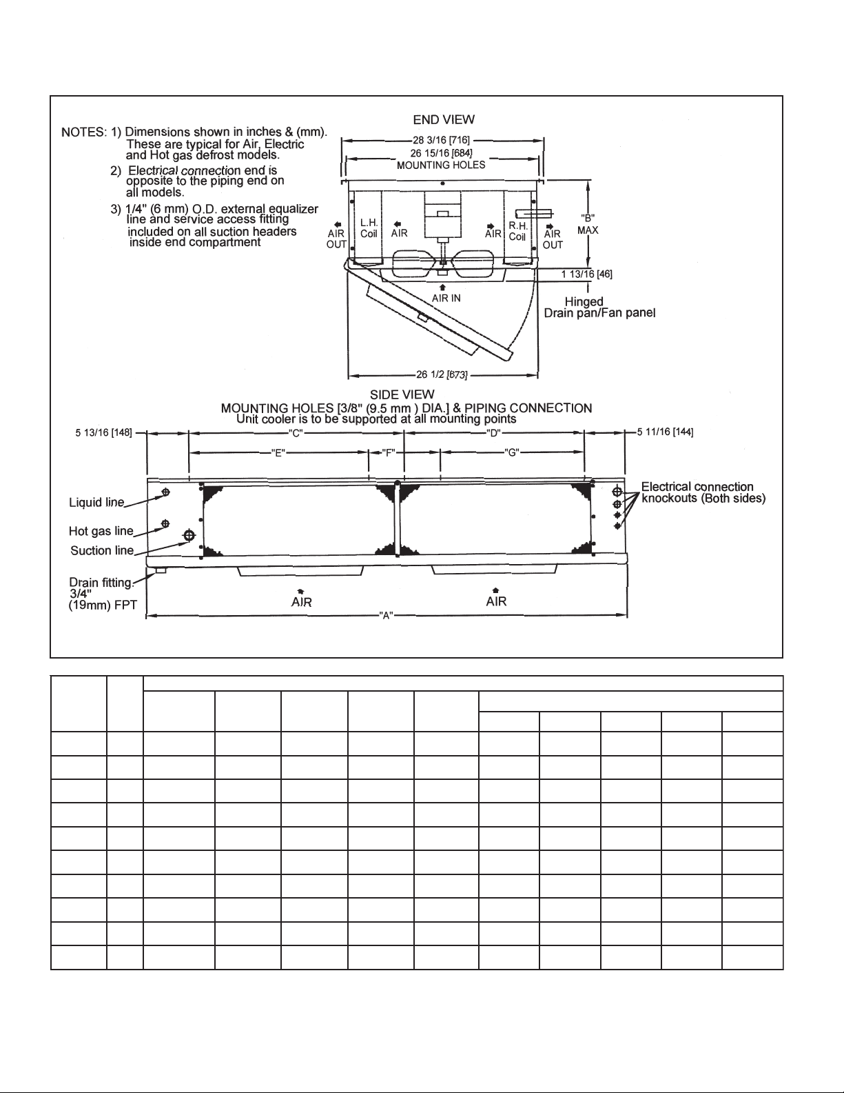
DIMENSIONAL DATA - Inches (mm)
.oN
LEDOM
fo
snaF
06018/5 )61( 2/1 )31( 2/1 )31(
09018/7 )22( 2/1 )31( 2/1 )3
02128/7 )22( 2/1 )31( 2/1 )31(
05128/11 )92( 2/1 )31( 2/1 )31(
08138/11 )92( 2/1 )31( 2/1 )31(
02238/11 )92( 2/1 )31( 2/1 )31(
07238/11 )92( 8/7* )22( 8/5 )61(
00348/11 )92( 8/7* )2
04348/31 )53( 8/7* )22( 8/5 )61(
07358/31 )53( 8/7* )22( 8/5 )61(
* Reducer supplied to accomodate 1/2” or 7/8” TXV outlet connection.
noitcuS
noitcennoC
)DO(
rotubirtsiD
telnI
)DO(
2( 8/5 )61(
saGtoH
.nnoCediS
)DO(
1(
AB
9961( )
8/766
)9961(
8/766
)9961(
8/766
8/766
)9961(
8/729
)9532(
8/729
)9532(
8/729
)9532(
8/729
)9532(
8/7211
)7682(
8/7211
)7682(
- 4 -
SEHCNI-ATADLANOISNEMID )mm(
seloHgnitnuoM
CDEFG
61/118
)122(
61/99
)252(
61/721
)613(
61/5141
)873(
61/5141
)873(
61/5141
)873(
61/771
)344(
61/771
)344(
61/771
)344
(
61/771
)344(
2/172
)996(
2/172
)996(
2/172
)996(
2/172
)996(
2/104
)9201(
2/104
)92
01(
2/104
)9201(
2/104
)9201(
--
--
2/172
)996(
2/172
)996(
2/
172
)996(
2/172
)996(
2/104
)9201(
2/104
)9201(
2/104
)9201(
2/104
)9201(
---
---
---
---
---
---
---
--2/104
)9201(
2/104
)9201(
02
)805(
02
)805(
2/104
)9201(
2/1
04
)9201(
Page 5
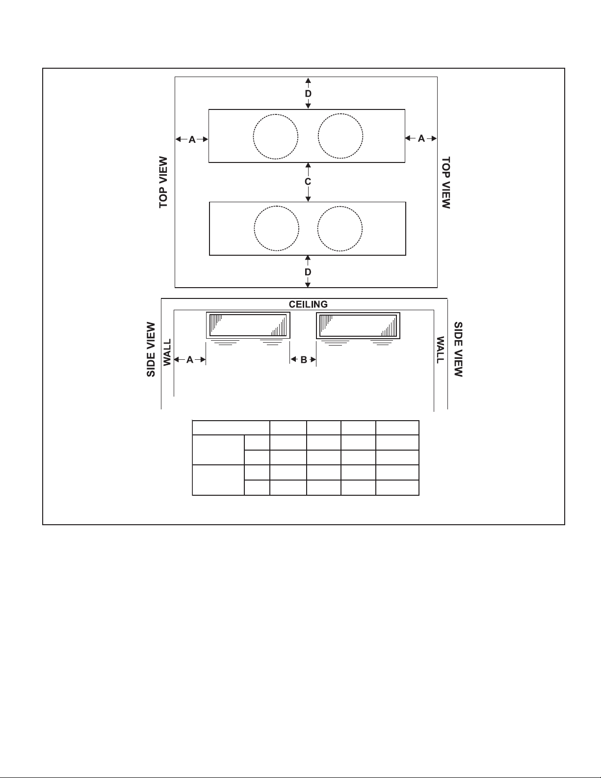
RECOMMENDED INSTALLATION CLEARANCES
NOISNEMIDABCD
.tf
muminiM
mumixaM
226 3
).mc()16()16()381()29(
.tf
-70402
).mc(- )012()0021()006(
- 5 -
Page 6
WIRING DIAGRAM
Air Defrost - All V olt ages
AIR DEFROST
TYPICAL WIRING:
WITH DEFROST TIME CLOCK
DEFROST CLOCK
PARAGON # 8145
OR EQUIVALENT
TM
3
12
4X
PUMP DOWN
N
SWITCH
(IF USED)
NAMEPLATE FOR ELECTRICAL
SPACE
THERMOSTAT
NOTE #4
FOR MULTIPLE EVAPORATORS AND OTHER
ALTERNATIVE WIRING, SEE INSTALLATION MANUAL
REFER TO EVAPORATOR
REQUIREMENTS
L2(N)
L1
GND
FUSE OR
CIRCUIT
BREAKER
NOTE #3
SOLENOID VALVE
OMIT
FUSE
IF (N)
LIQUID LINE
NOTE #4
WITHOUT DEFROST TIME CLOCK
REFER TO EVAPORATOR
NAMEPLATE FOR ELECTRICAL
REQUIREMENTS
L2(N)
L1
GND
FUSE OR
CIRCUIT
BREAKER
NOTE #3
OMIT
FUSE
IF (N)
SPACE
THERMOSTAT
NOTE #4
LIQUID LINE
SOLENOID VALVE
NOTE #4
4
F
TERMINAL BOARD
GND.
RIBBED
FAN
MTR
PLAIN
FAN
MTR
FAN
MTR
FAN
MTR
NOTES
1). USE COPPER CONDUCTORS ONLY
2). USE 75°C WIRE (OR HIGHER)
3). OVERCURRENT PROTECTION FOR
EVAPORATOR FAN MOTORS AND DEFROST
HEATERS MUST NOT EXCEED MAXIMUM
VALUE SHOWN ON EVAPORATOR NAMEPLATE.
4). MAY BE FACTORY INSTALLED-MOUNTED
AND WIRED ON EVAPORATOR
(PRE-ASSEMBLED MODELS)
EVAPORATOR
FAN MOTOR
POWER PLUGS
REFER TO EVAPORATOR
FAN
DATA PLATE FOR
MTR
MOTOR QUANTITY
4
F
TERMINAL BOARD
GND.
TERMINALS
DH -DRAIN PAN HEATER
-COMP0NENT TERMINAL - MARKED
-COMPONENT TERMINAL - UNMARKED
( IDENTIFIABLE BY LOCATION )
-COMPONENT TERMINAL - UNMARKED
( UNIDENTIFIABLE )
-TERMINAL BLOCK TERMINAL
-WIRE SPLICE
CONDUCTORS/WIRING
ALL FIELD WIRING MUST BE DONE IN
COMPLIANCE WITH ALL APPLICABLE LOCAL
AND NATIONAL CODES.
PLAIN
RIBBED
FAN
FAN
MTR
MTR
FACTORY WIRING
WIRING BY OTHERS
OPTIONAL FACTORY OR
BY OTHERS
FAN
FAN FAN
MTR
MTR
EVAPORATOR
FAN MOTO R
POWER PLUGS
REFER TO EVAPORATOR
DATA PLATE FOR
MTR
MOTOR QUANTITY
REV A
11/05/01
1073979
- 6 -
Page 7

DEFROST CLOCK
YL
PARAGON # 8145
OR EQUIVALENT
3
12
TERMINAL
BOARD
GND.
WIRING DIAGRAM
Electric Defrost - Single Evaporator
ELECTRIC DEFROST
EVAPORATOR WITH DEFROST HEATER CONTACTOR
TYPICAL WIRING:
TM
4NX
COMPR CONTACTOR
AUXILLARY
(DEFR. HTR. LOCKOUT)
PUMP DOWN
SWITCH
(IF USED)
OR JUMPER
4
FAN
MTR
X
F
RD
DEFROST TERMINATION
(CLOSES AT 55°F)
(OPENS AT 35°F)
PLAIN
RIBBED
FAN
MTR
FAN
MTR
FUSE OR
CIRCUIT
BREAKER
NOTE #3
SPACE
THERMOSTAT
NOTE #4
ORANGE
3
JUMPER
RD
FAN
MTR
FOR MULTIPLE EVAPORATORS AND OTHER
ALTERNATIVE WIRING, SEE INSTALLATION MANUAL
REFER TO EVAPORATOR
NAMEPLATE FOR ELECTRICAL
L3
L3
T3
N
RD
NOTE #6
DEFROST
HEATER
CONTACTOR
TO H3
GND
FUSE OR
CIRCUIT
BREAKER
NOTE #3
LIQUID LINE
SOLENOID VALVE
NOTE #4
"Y"
H1
BK
R.H. COIL
BOTTOM
BK
BK
L.H. COIL
BOTTOM
BK
R.H.COIL
TOP
BK
FAN MOTOR
POWER PLUGS
REFER TO EVAPORATOR
DATA PLATE FOR
FAN
MOTOR QUANTITY
MTR
C
H2
L.H.
DRAIN PAN
YL
DRAIN PAN
BK
YL
L.H.COIL
TOP
BK
EVAPORATOR
L1
ORANGE
JUMPER
YL
R.H.
L2
L2
L1
T2
T1
H3
YL
BK
FOR THREE PHASE
NOTE #6
H1
DRAIN PAN
YL
BK
BK
H2
YL
L.H.
R.H.
DRAIN PAN
YL
L.H.COIL
TOP
BK
NOTE #5
BK
R.H. COIL
BOTTOM
BK
L.H. COIL
BOTTOM
BK
R.H.COIL
TOP
HEATER LOADS MUST NOT
EXEED CONTACT RATING.
FOR THREE PHASE HEATER
OPERATION (FIELD CONVERSION)
A. REMOVE ORANGE JUMPER
BETWEEN TERMINALS
H3
AND
H2
B. RECONNECT L.H. BOTTOM
HEATER WIRE (SHOWN AS "Y")
H1
FROM
TO
"Y"
BK
H3H2
YL
BK
NOTES
1). USE COPPER CONDUCTORS ONLY
2). USE 75°C WIRE (OR HIGHER)
3). OVERCURRENT PROTECTION FOR
EVAPORATOR FAN MOTORS AND DEFROST
HEATERS MUST NOT EXCEED MAXIMUM
VALUE SHOWN ON EVAPORATOR NAMEPLATE.
4). MAY BE FACTORY INSTALLED-MOUNTED
AND WIRED ON EVAPORATOR
(PRE-ASSEMBLED MODELS)
ON MULTIPLE PRE-ASSEMBLED EVAPORATORS
WIRE SECOND EVAPORATOR SOLENOID IN
PARALLEL WITH FIRST ONE. ONLY USE ONE
THERMOSTAT.
5). THESE HEATERS NOT USED ON _LV060ED
AND _LV090ED MODELS
- 7 -
TERMINALS
-COMP0NENT TERMINAL - MARKED
-COMPONENT TERMINAL - UNMARKED
( IDENTIFIABLE BY LOCATION )
-COMPONENT TERMINAL - UNMARKED
( UNIDENTIFIABLE )
-TERMINAL BLOCK TERMINAL
-WIRE SPLICE
CONDUCTORS/WIRING
ALL FIELD WIRING MUST BE DONE IN
COMPLIANCE WITH ALL APPLICABLE LOCAL
AND NATIONAL CODES.
FACTORY WIRING
WIRING BY OTHERS
OPTIONAL FACTORY
OR BY OTHERS
REV B
11/05/01
1073978
Page 8

WIRING DIAGRAM
Electric Defrost - Multiple Evaporators
FOR ALL MODELS USING DEFROST HEA TER CONT ACT OR
- 8 -
Page 9

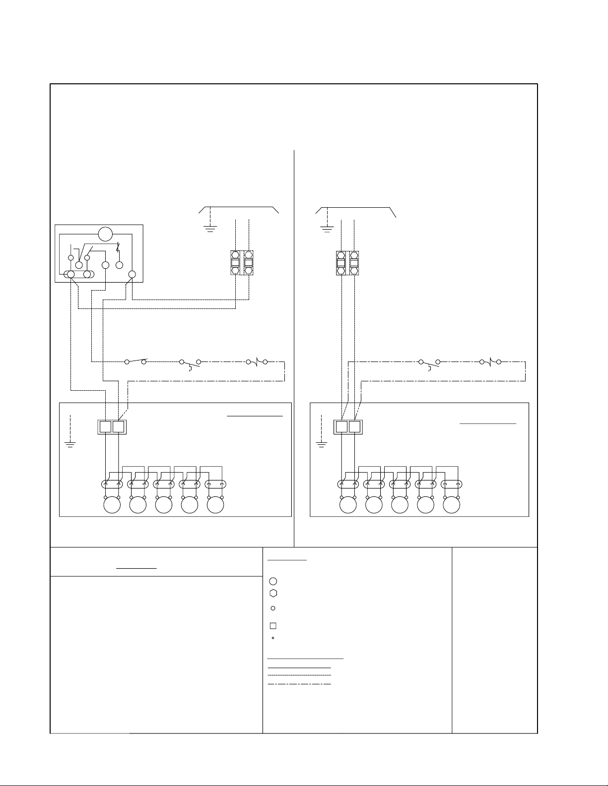
WIRING DIAGRAM
Electric Defrost - (For optional use on models 060ED and 090ED operating
on 200-220/1/50)
ELECTRIC DEFROST
EVAPORATOR WITHOUT DEFROST HEATER CONTACTOR
USING MAX 15A HEATER OVERCURRENT PROTECTION
TYPICAL WIRING:
FOR MULTIPLE EVAPORATORS AND OTHER
ALTERNATIVE WIRING, SEE INSTALLATION MANUAL
DEFROST CLOCK
PARAGON # 8145
OR EQUIVALENT
TM
X
4
231
4
F
GND.
PLAIN
RIBBED
N
PUMP DOWN
SWITCH
THERMOSTAT
(IF USED)
X
RD
3
RD
DEFROST TERMINATION
(CLOSES AT 55°F)
(OPENS AT 35°F)
REFER TO EVAPORATOR
NAMEPLATE FOR ELECTRICAL
REQUIREMENTS
L1
GND
FUSE OR
CIRCUIT
BREAKER
NOTE #3
SPACE
NOTE #4
ORANGE JUMPER
ORANGE
H1
JUMPER
LIQUID LINE
SOLENOID VALVE
NOTE #4
H2
R.H.
COIL
BK
BK
YL
L.H.
COIL
BK
BK
JMPR
YL
OR
L.H.
DRAIN
PAN
R.H.
DRAIN
PAN
H3
YL
YL
L2(N)
JMPR
MAX 15A
OR
N
NOTES
1). USE COPPER CONDUCTORS ONLY
2). USE 75°C WIRE (OR HIGHER)
3). OVERCURRENT PROTECTION FOR
EVAPORATOR FAN MOTORS AND DEFROST
HEATERS MUST NOT EXCEED MAXIMUM
VALUE SHOWN ON EVAPORATOR NAMEPLATE.
4). MAY BE FACTORY INSTALLED-MOUNTED
AND WIRED ON EVAPORATOR
(PRE-ASSEMBLED MODELS)
ON MULTIPLE PRE-ASSEMBLED EVAPORATORS
WIRE SECOND EVAPORATOR SOLENOID IN
PARALLEL WITH FIRST ONE. ONLY USE ONE
THERMOSTAT.
FAN
MTR
MTR MTR
FANFAN
MTR
RD
FAN M OTOR
POWER PLUGS
REFER TO EVAPORATOR
FAN
MTR
DATA PLATE FOR
MOTOR QUANTITY
EVAPORATOR
TERMINALS
-COMP0NENT TERMINAL - MARKED
-COMPONENT TERMINAL - UNMARKED
( IDENTIFIABLE BY LOCATION )
-COMPONENT TERMINAL - UNMARKED
( UNIDENTIFIABLE )
-TERMINAL BLOCK TERMINAL
-WIRE SPLICE
CONDUCTORS/WIRING
ALL FIELD WIRING MUST BE DONE IN
COMPLIANCE WITH ALL APPLICABLE LOCAL
AND NATIONAL CODES.
FACTORY WIRING
WIRING BY OTHERS
OPTIONAL FACTORY
OR BY OTHERS
1074180
REV-A
FAN
- 9 -
Page 10

WIRING DIAGRAM
Hot Gas Defrost - All Voltages
REVERSE CYCLE AND 3-PIPE HOT GAS DEFROST
- 10 -
Page 11

THERMOSTATIC EXPANSION VALVE SELECTION - SPORLAN
.ONLEDOMF°DT
060
090
021
051
081
022
072
003
043
073
01
51
01
51
01
51
01
51
01
51
01
51
01
51
01
51
01
51
01
51
F°001NODESABSNOITCELES )C°7.73( DIUQIL
DT(C°)
(6.5)
(3.8)
(6.5)
3.8()
(6.5)
(3.8)
(6.5)
(3.8)
(6.5)
(3.8)
(6.5)
(3.8)
(6.5)
3.8()
(6.5)
(3.8)
(6.5)
(3.8)
(6.5)
()3.8
22RA404R705R
4/3-EVGEC-C-2/1-ESGE
C-1-EVGEC-1-ESG
C-2/11-EVGEC-2/11-ESGEC-2/11-EPGE
C-2-EVGE
C-3-EVGE
C-4-EVSC-4-ESSC-4-EPS
EC-1-EPGE
C-2-ESGEC-2-EPGE
C-3-ESSC-3-EPS
C-2/1-EPGE
C-1-EPGE
DISTRIBUTOR NOZZLE SELECTION
SELZZONDRADNATSSLEDOMLLAROFDELLATSNIYROTCAF
.D.T
EGNAR.PMET.PAVE F°04OTF°81 )C°4.4O
TNAREGIRFER 22R, A404-R705R,
060
090
021051,
081
022
072
003
043073,
F°001
NODESABSNOITCELES )C°7.73( DIUQIL
F°21OTF°8 )C°6.6otC°4.4(
TC°7.7-(
4/3-L
1-L
2/11-L
2-L
2/12-L
2/12-G
3-G
4-G
- 1 1-
Page 12

FAN/HEATER CONTROL AND DEFROST TERMINATION CONTROL POSITION
HOT GAS DEFROST (REVERSE CYCLE)
HOT GAS DEFROST (3-PIPE OR BYPASS)
- 12 -
Page 13

INSTALLATION INSTRUCTIONS
INST ALLATION
The installation and start-up of LV Unit Coolers should only be
performed by qualified refrigeration mechanics.
This equipment should be installed in accordance with all
applicable codes, ordinances and local by-laws.
INSPECTION
Inspect all equipment before unpacking for visible signs of
damage or loss. Check shipping list against material received to
ensure shipment is complete.
IMPORTANT: Remember, you, the consignee, must make any
claim necessary against the transportation company. Shipping
damage or missing parts, when discovered at the outset, will
prevent later unnecessary and costly delays.
If damage or loss during transport is evident, make claim to
carrier, as this will be their responsibility , not the
manufacturer’s.
Should carton be damaged, but damage to equipment is not
obvious, a claim should be filed for “concealed damage” with the
carrier.
IMPORTANT: The electrical characteristics of the unit should be
checked at this time to make sure they correspond to those
ordered and to electrical power available at the job site.
Save all shipping papers, tags and instruction sheets for
reference by installer and owner.
blow directly out, through an opened door and that the
product does not obstruct the free circulation of air. Allow a
minimum of 24” clearance at each end. LV Unit Coolers
draw air through the fans and discharge air through both
coils.
Consideration should be given to the coil location in order to
minimize the piping run length to the condensing unit and
floor drain.
EXP ANSION VAL VE (TXV) SELECTION
All units require the use of an externally equalized
expansion valve. (A 1/4” (6 mm) O.D. equalizer line has
been provided on the coil) TX valves should not be selected
strictly by their nominal ton rating. (This rating is based at a
specific pressure differential and entering liquid
temperature). Since applications will differ it is suggested
the following selection procedure be followed.
1. Determine actual unit cooler BTUH or KW (thermal).
The nominal rating is based at 10 °F T.D. (5 .5°C)
(Room Temp. minus Evap. Temp.). Note that a higher /
lower operating T.D.will increase / decrease this capacity
rating by their direct ratio.
2. Determine the pressure drop across the valve by
subtracting the suction (evaporating) pressure from the
high side liquid pressure. Note: Also subtract the
distributor pressure loss (use approx. 25 psig (1.1 bar)
for R134a and 35 psig (2.4 bar) for R22, R404A, R507).
APPLICA TION
LV Unit Coolers are designed for use with R22, R404A, R134a,
or R507 refrigerants. At room temperatures above 34°F (1.1 C)
(and evaporating temps no lower than 24 °F (-4.4°C)) positive
coil defrosting (Electric or Hot Gas) is not required. (The air
flowing through the coil will accomplish the defrost). At room
temperatures of 34°F (1.1
required (either Electric (ED) or Hot Gas (HE, RE, TE) in model
nomenclature). These models require the use of (1) Time Clock
or equivalent (to initiate and terminate the defrost cycle), and (2)
Defrost Termination Control (to prevent unnecessary prolonged
heating and steaming of the coil once all the ice and frost has
melted), (3) Hot Gas models also utilize a Fan/Heater drain pan
control.
The coil must not be exposed to any abnormal atmospheric or
acidic environments. This may result in corrosion to the cabinet
and possible coil failure (leaks). (Consult manufacturer for
optional baked on phenolic protective coatings).
°
C) and below, positive defrosting is
LOCA TION
The unit location in the room should be selected to ensure
uniform air distribution throughout the entire space to be
refrigerated. Be sure that the unit does not draw air in, or
3. Estimate entering liquid temperature. Temperatures
lower than 100 °F (37.7 °C) increase valve capacity
ratings. Refer to valve manufacturer’s specs for details.
4. Select valve from the valve manufacturer selection charts
for the appropriate refrigerant, evaporating temp and
pressure drop.
5. After following the manufacturer’s installation instructions
and after the room has reached the desired temperature
the valve superheat should be checked. This will confirm
that the evaporator is operating properly and performing
to maximum efficiency. The superheat should be
around 5 (2.7°C) to 8 °F (4.4°C) for a 10 to 12 °F
(5.5 to 6.6°C) T.D. Too high or low a super heat will result
in unsatisfactory system performance and possible
compressor problems.
NOZZLE INST ALLATION
All LV Unit Coolers have nozzles installed at factory. For
nozzle selection refer to selection table. In case it is
required to install the nozzle at some point in the future, the
nozzle retainer clip (in distributor) must be removed before
inserting nozzle. Re-install clip ensuring nozzle is properly
in place.
- 13 -
Page 14

INSTALLATION INSTRUCTIONS (cont’d)
MOUNTING
Refer to dimensional drawing for recommended mounting
arrangements. Formed mounting channels are provided for
flush mounting to the ceiling. Ensure adequate clearance (at
least 24” (600 mm)) is provided at each end (to enable
access to the electrical and refrig. compartments).
Ensure that the ceiling is level since the drain pan has been
sloped for drainage during the defrost cycle.
DRAIN LINE
The drain line should be run from the drain connection,
sloping at least 1/4” (6 mm) per foot. A trap in a warm area
outside the room will allow proper draining through the
tubing. Connection should be made to proper drainage
facilities that comply with local regulations.
To prevent freeze-up when the temperature of the refrigerated
space is 35
heated along its run inside the cold room. The heated drain
line should be insulated. It is recommended that the heater
be energized at all times. A heat input of 20 watts per foot in a
28°F (-2.2°C) room, is satisfactory. Drain line heaters are not
required for constant room temperature above 35°F (1.6°C).
Ensure that the drain line has sufficient slope for proper
drainage (prevention of ice build up/blockage in pan).
o
F (1.7 °C) or lower, the drain line should be
PIPING
Refrigerant line sizes are important and may not be the same
size as the coil connections. Consult “Recommended
refrigerant line sizes” charts in any standard reference book
for proper line sizing.
Refrigerant piping and control system should be designed to
prevent possible liquid slugging (from oil or refrigerant) of the
compressors on start-up after the defrost cycle. On Hot Gas
Defrost Systems the suction accumulator should be at least
2.5 times the coils operating charge.
See Dimensional data for line locations. For Reverse Cycle
and Hot Gas models and 3-Pipe - see fig. 2 & 3 respectively
on page 12 for typical unit piping. These models include a
check valve (unmounted) packaged along with the nozzle in
the refrig. connection compartment end panel.
WIRING
Wire system in accordance with governing standards and
local codes. See data and wiring diagrams on pages 6 to 10
for wiring arrangement. Electrical wiring is to be sized in
accordance with minimum circuit ampacity rating (MCA).
For ease of identifying the proper wiring terminal, unit wiring
is color coded and terminal block connections are identified.
SYSTEM CHECK
Before Start-Up:
1. All wiring should be in accordance with local codes.
2. Refrigerant lines should be properly sized.
3. Off cycle defrost and electric defrost systems preferably
must include a liqud line solenoid valve and suction
accumulator.
4. Thorough evacuation and, dehydration has been
performed.
5. The suction, discharge, and receiver service valves must
be open.
6. The system preferably must include a liquid line drier
moisture indicator and suction filter.
7. Pour enough water into the drain pan to allow a good check
on drainage and seal the trap.
After Start-Up:
1. Check the oil level to be sure the oil charge is correct.
2. On initial start up the fans do not start until coil
temperature is pulled down to approximately 35 °F (1.7 °C)
on the hot gas coil. Also, it is normal for the fans to cycle a
few times until the room temperature is pulled down.
3. Fan/Heater control and defrost termination control is
factory installed for reverse cycle defrost operation. Refer
to Fig. 1 on page 12.
4. If coil is to be used for 3-pipe (bypass) Hot Gas Defrost,
Fan/Heater must be moved from suction line to hot gas
inlet line and the defrost termination control moved to the
suction line. Refer to Fig. 1 on page 12.
5. In general, evaporators running with a TD of 10 °F should
have a superheat reading of 5° to 8 °F (2.7 °C to 4.4 °C).
For evaporators with a higher TD, the superheat should be
8° to 12°F (4.4 °C to 6.6 °C).
6. Heavy moisture loads are usually encountered when
starting the system for the first time. This will cause a rapid
build-up of frost on the unit cooler. During the initial pull
down, we suggest that the frost build-up be watched and
defrosted manually as required. This may be done by
rotating the inner dial on the timer until the pin in the outer
dial is directly opposite the timer pointer. (Paragon 814520 Timer by others).
7. Observe that the system goes through at least one
complete DEFROST CYCLE.
MAINTENANCE
The unit should be periodically inspected for any dirt or
build-up on the fin surface and cleaned if necessary with a
soft whisk or brush. Also ensure coils inner and outer drain
pans do not have any ice build-up from improper defrost
operation. When replacing heater elements first remove
heater retainer brackets and heater clips.
- 14 -
Page 15

SERVICE PARTS LIST
srotoM sledoMrebmuNtraP
PH51/1,CSPV511-V001
PH51/1,CSPV032-V002
sretaeH
HecaFlioC
HecaFlioC
sedalBnaF
sedalB5°53"41
sedalB5°23"41
sedalB5°22"41
lortnoCretaeH/naF )EH&ER(sled
noitanimreTtsorfeD llA
drauGnaF llA
W056,V511,retae
W039,V511,retaeHecaFlioC
W0411,V511,retae
W092,V511,retaeHnaPniarD
W014,V511,retaeHnaPniarD
W015,V511,retaeHnaPniarD
llA
llA
051,021,090,060
003,072,022,081
073,043
051,021,090,060
003,072,022,081
073,043
043,072,090
073,003,022,051
081,021,060
oMtsorfeDsaGtoH
3043701
5043701
300-4580701
200-4580701
100-4580701
600-4580701
500-4580701
400-4580701
4143701
5143701
6143701
0463701
0821701
6543701
- 15 -
Page 16

NOTES
- 16 -
Page 17

NOTES
- 17 -
Page 18

SERVICE LOG
ETADSTNEMMOC
- 18 -
Page 19

FINISHED GOODS WARRANTY
The terms and conditions as described below in the General Warranty Policy cover all products
manufactured by National Refrigeration.
GENERAL WARRANTY POLICY
Subject to the terms and conditions hereof, the Company warrants all Products, including Service
Parts, manufactured by the Company to be free of defects in material or workmanship, under normal
use and application for a period of one (1) year from the original date of installation, or eighteen (18)
months from the date of shipment from the Company, whichever occurs first. Any replacement
part(s) so supplied will be warranted for the balance of the product’s original warranty. The part(s) to
be replaced must be made available in exchange for the replacement part(s) and reasonable proof of
the original installation date of the product must be presented in order to establish the effective date
of the warranty , failing which, the ef fective date will be based upon the date of manufacture plus thirty
(30) days. Any labour, material, refrigerant, transportation, freight or other charges incurred in connection with the performance of this warranty will be the responsibility of the owner at the current
rates and prices then in effect. This warranty may be transferred to a subsequent owner of the
product.
THIS WARRANTY DOES NOT COVER
(a) Damages caused by accident, abuse, negligence, misuse, riot, fire, flood, or Acts of God (b) damages
caused by operating the product in a corrosive atmosphere (c) damages caused by any unauthorized
alteration or repair of the system affecting the product’s reliability or performance (d) damages caused
by improper matching or application of the product or the product’s components (e) damages caused
by failing to provide routine and proper maintenance or service to the product (f) expenses incurred for
the erecting, disconnecting, or dismantling the product (g) parts used in connection with normal
maintenance, such as filters or belts (h) products no longer at the site of the original installation (i)
products installed or operated other than in accordance with the printed instructions, with the local
installation or building codes and with good trade practices (j) products lost or stolen.
No one is authorized to change this WARRANTY or to create for or on behalf of the Company any
other obligation or liability in connection with the Product(s). There is no other representation, warranty
or condition in any respect, expressed or implied, made by or binding upon the Company other than the
above or as provided by provincial or state law and which cannot be limited or excluded by such law , nor
will we be liable in any way for incidental, consequential, or special damages however caused.
The provisions of this additional written warranty are in addition to and not a modification of or subtraction
from the statutory warranties and other rights and remedies provided by Federal, Provincial or State
laws.
PROJECT INFORMATION
metsyS
rebmuNledoM pU-tratSfoetaD
rebmuNlaireS rotcartnoCecivreS
tnaregirfeRenohP
ylppuSlacirtcelExaF
- 19 -
Page 20

“AS BUILT” SERVICE PARTS LIST
04/14/2008
Service Parts ListService Parts List
Service Parts List
Service Parts ListService Parts List
LL
abelabel
L
abel
LL
abelabel
TT
o Be Ao Be A
T
o Be A
TT
o Be Ao Be A
HEREHERE
HERE
HEREHERE
ttachedttached
ttached
ttachedttached
®
General Sales, PGeneral Sales, P
General Sales, P
General Sales, PGeneral Sales, P
135 Little Nine Drive, Morehead City135 Little Nine Drive, Morehead City
135 Little Nine Drive, Morehead City
135 Little Nine Drive, Morehead City135 Little Nine Drive, Morehead City
252-240-2829 • 1-800-24-BALL252-240-2829 • 1-800-24-BALL
252-240-2829 • 1-800-24-BALL
252-240-2829 • 1-800-24-BALL252-240-2829 • 1-800-24-BALL
e-mail: ballysales@ballyrefboe-mail: ballysales@ballyrefbo
e-mail: ballysales@ballyrefbo
e-mail: ballysales@ballyrefboe-mail: ballysales@ballyrefbo
Due to Manufacturer’s policy of continuous product improvement,
the Manufacturer reserves the right to make changes without notice.
arar
ts & Serts & Ser
ar
ts & Ser
arar
ts & Serts & Ser
vice Manufacturing & Engineeringvice Manufacturing & Engineering
vice Manufacturing & Engineering
vice Manufacturing & Engineeringvice Manufacturing & Engineering
xx
x
xx
, NC 28557, NC 28557
, NC 28557
, NC 28557, NC 28557
Y • FY • F
AX: 252-240-0384AX: 252-240-0384
Y • F
AX: 252-240-0384
Y • FY • F
es.com • wwwes.com • www
es.com • www
es.com • wwwes.com • www
AX: 252-240-0384AX: 252-240-0384
.ballyrefbo.ballyrefbo
.ballyrefbo
.ballyrefbo.ballyrefbo
xx
es.comes.com
x
es.com
xx
es.comes.com
DISTRIBUTED BY:
 Loading...