

Page 1
PRODUCT DA T A &
Electric Defrost
Medium Profile
BB Unit Coolers
INSTALLATION
Bulletin: B30-BBE-PDI-15
1048680
Medium and low Temp Applications
°F Room Temp. or Higher)
(-30
Electrical Power: Three Phase
* Heavy gauge textured aluminum cabinet
construction resists scratches/corrosion and
minimizes weight for shipment, installation and
service.
* Attractive and durable high density polyethylene
fan guards with built-in throw boosters.
* 3/8 Tubing coil construction (reduces operating
charge).
* VENTURI-FLO Distributor eliminates need for
distributor nozzle selections.
* Adjustable Defrost Termination Thermostat with
dual Fan Delay function.
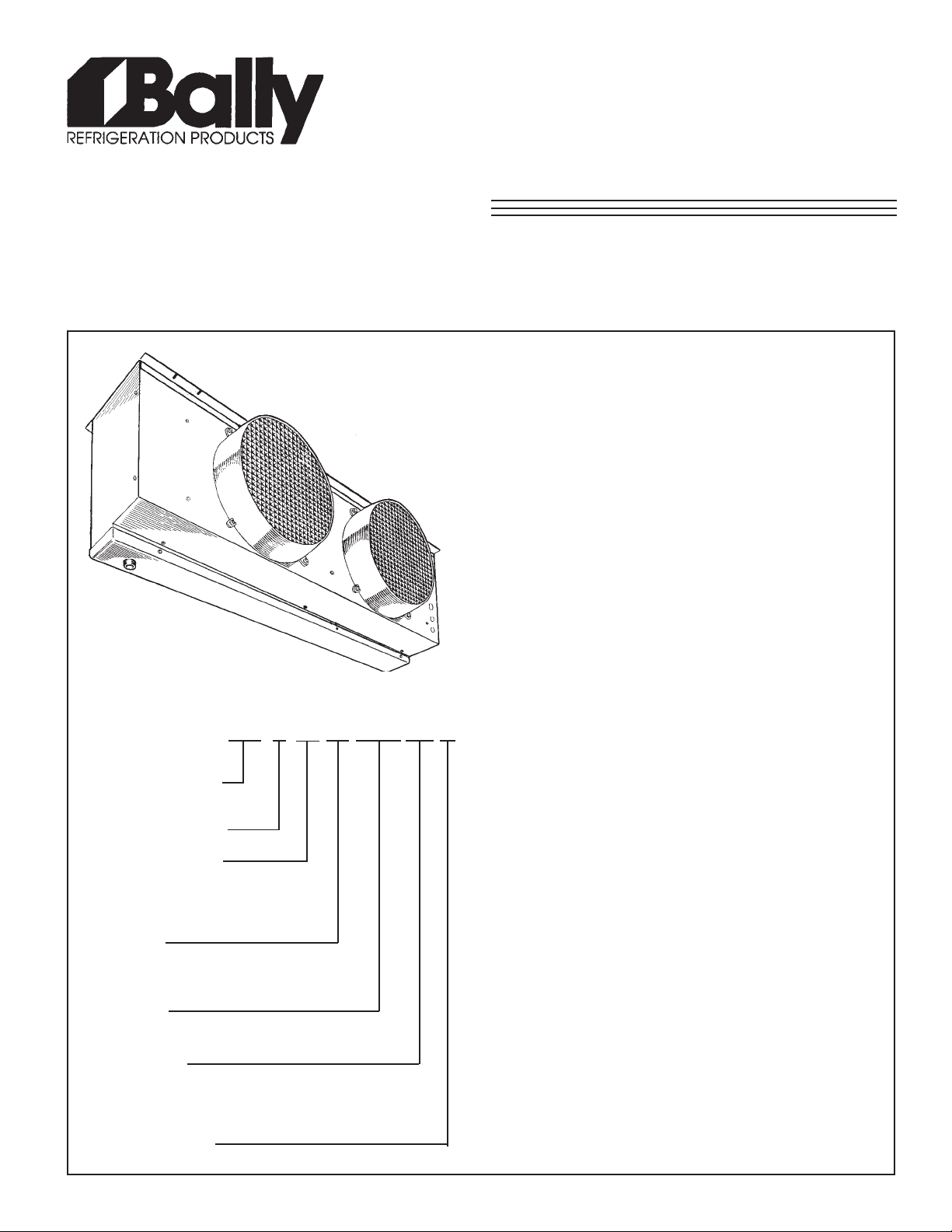
NOMENCLATURE
BB
BALLY
MEDIUM PROFILE
UNIT COOLER
NUMBER OF FANS
MBH CAPACITY AT
o
10
F T .D. (60Hz)
SIZE 24 = 24,000 BTUH
OF COOLING
OPTIONS
P = PRE ASSEMBLED REMOTE
S = STANDARD UNIT
DEFROST
ED = ELECTRIC DEFROST
ELECTRICAL
T3 = 208-230/3/60 T4 = 460/3/60
T5 = 575/3/60 T7 = 200-220/3/50
T8 = 380/3/60 T9 = 380-400/3/50
REVISION LEVEL
24
1
* Stainless-Steel Defrost Heaters mounted on the
-ED-
P
T4 B
coil for service accessibility
* Refrigerants R12, R22, R502, R134a, R404A,
R407A, R407B, R407C, R507.
CONTENTS PAGE
Nomenclature.....................................
Capacity Data.....................................
Electrical Data....................................
Wiring Diagrams................................
Dimensional Data...............................
Alco TXV Selections...........................
Sporlan TXV Selections.....................
Pictorial Views....................................
Application..........................................
Installation..........................................
Inspection...........................................
Location..............................................
Mounting.............................................
Drain Line...........................................
Piping..................................................
Wiring.................................................
System Check....................................
Maintenance.......................................
Service Parts List...............................
Project Information............................
Cover
2,3
2,3
4,5
6
7
8
9
9
9
9
9
10
10
10
10
10
10
11
Back
Page 2
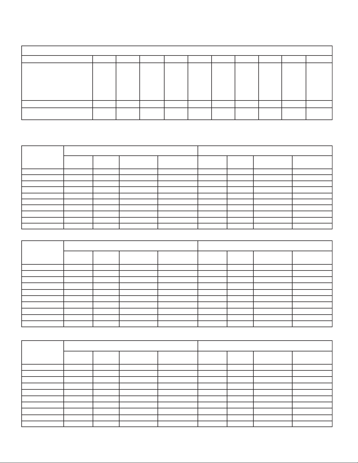
60Hz SPECIFICATIONS
Capacity Data - (BTUH) @ 10oF TD 60Hz
BBLEDOM
o
ERUTAREPMETPAVE
FDE-P611DE-P911DE-P421DE-P232DE-P832DE-P542DE-P152DE-P063DE-P863DE-P573
52+/02+
01+
0
01020304-
MFC
TNAREGIRFER
*EGRAHC
* R404A at -20oF S.S.T . with coil 30% full
LBS
KG
00091
02681
05081
09
271
05161
01051
08631
0013007405540049004900290019056310563105631
8.5
7.2
00032
04522
05812
03902
05591
07181
06561
4.5
4.2
00092
02482
05572
09362
05642
01922
08802
2.8
7
.3
00083
04273
63
001
08543
00323
02003
06372
5.8
9.3
00064
08054
00734
06814
00193
04363
02133
8.01
9.4
00035
04915
05305
03284
05054
07814
06183
6.21
7.5
00006
0088
5
00075
00645
00015
00474
00234
1.61
3.7
00007
00686
00566
00736
00595
00355
00405
6.91
9.8
00008
00487
00067
00827
00086
00236
00675
4.22
2.01
00088
04268
00638
08008
00847
02596
06336
5.42
2.11
208-230/3/60
LEDOM
B3T-DE-P611BB10.25.25102342.114102
B3T-DE-P911BB10.25.25100168.518.9152
B3T-DE-P421BB10.25.25100168.518.9152
BB20.45.451086112.038.7354
B3T-DE-P232
B3T-DE-P832BB20.45.451086112.038.7354
B3T-DE-P542BB20.45.451086112.038.7354
B3T-DE-P152BB20.45.451086112.038
B3T-DE-P063BB30.65.651052717.449.5506
B3T-DE-P863BB30.65.651052717.449.5506
B3T-DE-P573BB30.65.651052717.449.5506
YTQ
ELECTRICAL DATA 60HZ
SROTOMNAF SRETAEHTSORFED
LATOT
ALF
.CRIC.NIM
YTICAPMA
ESUF.XAM
)SPMA(
STTAWSPMA
.CRIC.NIM
YTICAPMA
.7354
460/3/60
SROTOMNAF SRETAEHTSORFED
LEDOM
YTQ
B4T-DE-P611BB10.152.15102346.57 51
B4T-DE-P911BB10.152.15100169.79.951
B4T-DE-P421BB10.152.15100169.79.951
B4T-DE-P232BB20.
B4T-DE-P832BB20.252.251086111.519.8152
B4T-DE-P542BB20.252.251086111.519.8152
B4T-DE-P152BB20.252.251086111.5
B4T-DE-P063BB30.352.351052713.229.7203
B4T-DE-P863BB30.352.351052713.229.7203
B4T-DE-P573BB30.352.351052713.229.7203
LATOT
ALF
252.251086111.519.8152
.CRIC.NIM
YTICAPMA
ESUF.XAM
)SPMA(
STTAWSPMA
19.8152
.CRIC.NIM
YTICAPMA
AM
AM
ESUF.X
)SPMA(
ESUF.X
)SPMA(
575/3/60
LEDOM
B5T-DE-P611BB18.01 5102345.46.551
B5T-DE-P911BB18.01 5100163.69.751
B5T-DE-P421BB18.01 5100163.69.751
B5T-DE-P232BB26.18.1510861
B5T-DE-P832BB26.18.151086111.211.5102
B5T-DE-P542BB26.18.151086111.211.5102
B5T-DE-P152BB26.18.151086111.211.5102
-P063BB34.26.251052719.714.2252
B5T-DE
B5T-DE-P863BB34.26.251052719.714.2252
B5T-DE-P573BB34.26.251052719.714.2252
All Fan Motors are 3/4 H.P .
SROTOMNAF SRETAEHTSORFED
YTQ
LATOT
ALF
.CRIC.NIM
YTICAPMA
ESUF.XAM
)SPMA(
STTAWSPMA
11.211.5102
.CRIC.NIM
YTICAPMA
AM
ESUF.X
)SPMA(
- 2-
Page 3
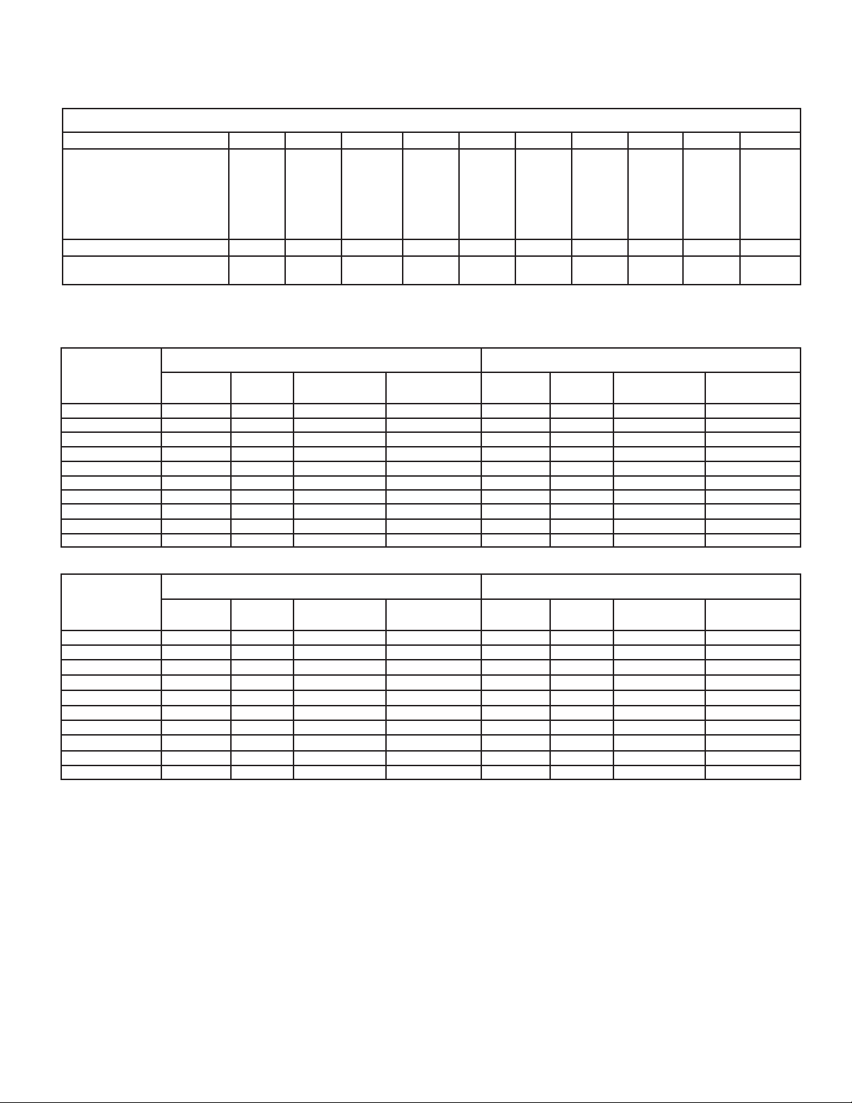
50Hz SPECIFICATIONS
Capacity Data - (BTUH) @ 10oF TD 50Hz
BBLEDOM
o
ERUTAREPMETPAVE
FDE-P611DE-P911DE-P421DE-P232DE-P232DE-P542DE-P152DE-P063DE-P863DE-P573
52+/02+
01+
0
01020304-
MFC
TNAREGIRFER
*EGRAHC
* R404A at -20oF S.S.T . with coil 30% full
LBS
KG
08471
03171
60661
70
951
85841
90831
68521
0752009308730087008700870557033110563105631
8.5
7.2
06112
73702
20102
65291
68971
61761
53251
4.5
4.2
08662
64162
64352
97242
87622
77012
01291
2.8
7
.3
06943
16243
33
212
41813
61792
81672
17152
5.8
9.3
02324
47414
40204
11583
27953
33433
07403
8.01
9.4
06784
58774
22364
27344
64414
02583
70153
6.21
7.5
00255
6904
5
04425
23205
02964
80634
44793
1.61
3.7
00446
21136
08116
40685
04745
67805
86364
6.91
9.8
00637
82127
02996
67966
06526
44185
29925
4.22
2.01
06908
14397
21967
47637
61886
85936
19285
5.42
2.11
200-220/3/50
LEDOM
-P232BB24.338.351586017.726.4304
380-400/3/50
LEDOM
T-DE-P063BB34.26.25105271728.3304
ELECTRICAL DATA 50HZ
SROTOMNAF SRETAEHTSORFED
YTQ
B7T-DE-P611BB17.131.25105937.014.3151
B7T-DE-P911BB17.131.25108555.411.8102
B7T-DE-P421BB17.131.25108555.411.8102
B7T-DE
B7T-DE-P832BB24.338.351586017.726.4304
B7T-DE-P542BB24.338.351586017.726.4304
B7T-DE-P152BB24.338.
B7T-DE-P063BB31.535.551587519.041.1555
B7T-DE-P863BB31.535.551587519.041.1555
B7T-DE-P573BB31.535.551587519.041.1
YTQ
B9T-DE-P611BB18.00.15102348.65.851
B9T-DE-P911BB18.00.15100166.92151
B9T-DE-P421BB18.00.15100166.92151
B9T-DE-P232BB26.18.15
B9T-DE-P832BB26.18.151086113.819.2252
B9T-DE-P542BB26.18.151086113.819.2252
B9T-DE-P152BB26.18.151086113.819.2252
B9
B9T-DE-P863BB34.26.25105271728.3304
B9T-DE-P573BB34.26.25105271728.3304
LATOT
ALF
LATOT
ALF
.CRIC.NIM
YTICAPMA
351586017.726.4304
SROTOMNAF SRETAEHTSORFED
.CRIC.NIM
YTICAPMA
ESUF.XAM
)SPMA(
ESUF.XAM
)SPMA(
1086113.819.2252
STTAWSPMA
STTAWSPMA
.CRIC.NIM
YTICAPMA
555
.CRIC.NIM
YTICAPMA
AM
AM
ESUF.X
)SPMA(
ESUF.X
)SPMA(
All Fan Motors are 3/4 H.P .
- 3 -
Page 4
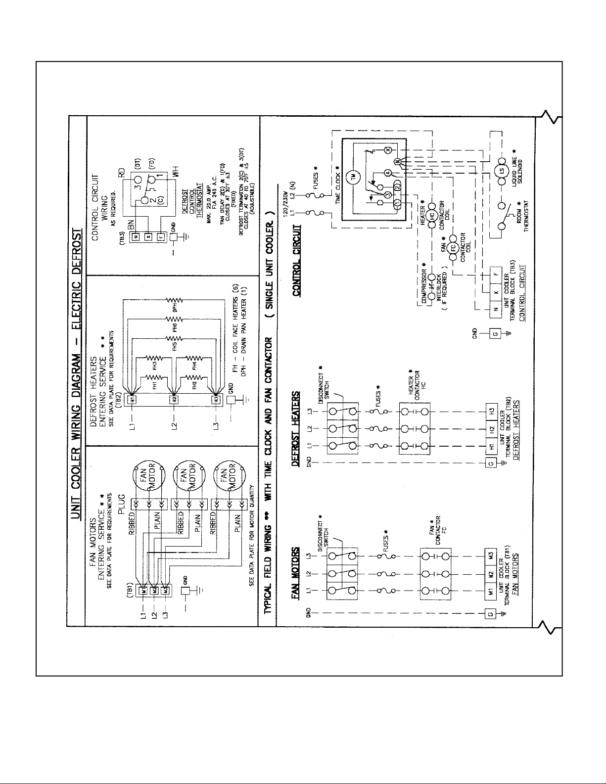
WIRING DIAGRAM
- 4 -
Page 5

WIRING DIAGRAM
- 5 -
Page 6

116
DIMENSIONAL DATA
119
124
232 238
245 251
360
368
375
DIMENSIONAL DATA
INCHES (MILLIMETERS)
Electric Defrost Model 116 119 124 232 238 245 251 360 368 375
Number of Fans
Liquid Connection (O.D. Sweat)
Suction Connection (O.D. Sweat)
Approx. Shipping Weight
Lbs.
Kg
1 1 1 2 2 2 2 3 3 3
5/8
(16)
7/8
(22)
160 190 205 350 370 380 390 540 560 580
73 86 93 159 168 173 177 245 227 264
7/8
(22)
1 1/8
(29)
7/8
(22)
1 3/8
(35)
7/8
(22)
1 3/8
(35)
7/8
(22)
1 5/8
(41)
7/8
(22)
1 5/8
(41)
7/8
(22)
1 5/8
(41)
7/8
(22)
1 5/8
(41)
1 1/8
(29)
2 1/8
(54)
1 1/8
(29)
2 1/8
(54)
- 6 -
Page 7

ALCO TXV SELECTIONS
R404A - R507
EVAP TEMP
+20/+25oF
+10oF
0oF
-10oF
-20oF
-30oF
-40oF
EVAP TEMP
+20/+25oF
+10oF
0oF
-10oF
-20oF
-30oF
-40oF
BTUH VALVE # BTUH VALVE# BTUH VALVE # BTUH VALVE # BTUH VALVE #
19000
18620
18050
17290
16150
15010
13680 HFES 2-RZ
BTUH VALVE # BTUH VALVE # BTUH VALVE # BTUH VALVE # BTUH VALVE #
53000
51940
50350
48230
45050
41870
38160 HFES 7-RZ 43200 HFES 7-RZ 50400 HFES 10-RZ
R22
EVAP
TEMP
+20/+25oF
+10oF
0oF
-10oF
-20oF
-30oF
-40oF
EVAP
TEMP
+20/+25oF
+10oF
0oF
-10oF
-20oF
-30oF
-40oF
116P-ED 119P-ED 124P-ED 232P-ED 238P-ED
BTUH VALVE # BTUH VALVE# BTUH VALVE # BTUH VALVE # BTUH VALVE #
19000
18620
18050
17290
16150
15010
13680
245P-ED 251P-ED 360P-ED 368P-ED 375P-ED
BTUH VALVE # BTUH VALVE # BTUH VALVE # BTUH VALVE # BTUH VALVE #
53000
51940
50350
48230
45050
41870
38160
MODEL BB
116P-ED 119P-ED 124P-ED 232P-ED 238P-ED
HFES
1 1/2-RC
HFES
1 1/2-RZ
23000
22540
21850
20930
19550
18170
16560
HFES
1 1/2-RC
HFES
2-RZ
29000
28420
27550
26390
24650
22910
20880
HFES
2-RC
HFES
3 1/2-RZ
38000
37240
36100
34580
32300
30020
27360
HFES
3 1/2-RC
HFES
3 1/2-RZ
46000
45080
43700
41860
39100
36340
33120
3 1/2-RC
245P-ED 251P-ED 360P-ED 368P-ED 375P-ED
HFES
3 1/2-RC
HFES
5-RZ
60000
58800
57000
54600
51000
47400
HFES
3 1/2-RC
HFES
5-RZ
70000
68600
66500
63700
59500
55300
HFES
5-RC
HFES
7-RZ
80000
78400
76000
72800
68000
63200
57600
HFES
5-RC
HFES
7-RZ
HFES 10-RZ
88000
86240
83600
80080
74800
69520
63360
MODEL BB
HFES
1 1/2-HC
HFES
2-HZ
HFES
2 1/2-HZ
HFES
3-HC
HFES
5 1/2-HZ
23000
22540
21850
20930
19550
18170
16560
60000
58800
57000
54600
51000
47400
43200 HFES 8-HZ 57600 HFES 10-HZ
HFES
1 1/2-HC
HFES
2 1/2-HZ
HFES
5 1/2-HC
HFES
5 1/2-HZ
29000
28420
27550
26390
24650
22910
20880
70000
68600
66500
63700
59500
55300
50400
HFES
2-HC
HFES
2 1/2-HZ
HFES
3-HZ
HFES
5 1/2-RC
HFES
8-RZ
38000
37240
36100
34580
32300
30020
27360
80000
78400
76000
72800
68000
63200
HFES
2 1/2-HC
HFES
3-HZ
HFES
5 1/2-HZ
HFES
5 1/2-HC
HFES
8-HZ
46000
45080
43700
41860
39100
36340
33120
88000
86240
83600
80080
74800
69520
63360
HFES
3-HC
HFES
5 1/2-HZ
HFES
5 1/2-HC
HFES
8-HZ
HFES 10-HZ
HFES
HFES
5-RZ
HFES
7-RC
HFES
10-RZ
MODEL BB R134a
EVAP TEMP
+20/+25oF
+10oF
0oF
EVAP TEMP
+20/+25oF
+10oF
0oF
Where available use the HFESC series valve which includes sweat fittings with a removable/cleanable inlet screen.
Note: Above Selections are based on 100 oF Entering Liquid Temperature.
VENTURI - FLO distributor does not require the selection or use of distributor nozzles.
116P-ED 119P-ED 124P-ED 232P-ED 238P-ED
BTUH VALVE # BTUH VALVE# BTUH VALVE # BTUH VALVE # BTUH VALVE #
19000
18620
18050
HFES
1 1/2-MC
23000
22540
21850
HFES
1 3/4-MC
29000
28420
27550
HFES
1 3/4-MC
38000
37240
36100
HFES
2 1/2-MC
46000
45080
43700
245P-ED 251P-ED 360P-ED 368P-ED 375P-ED
BTUH VALVE # BTUH VALVE # BTUH VALVE # BTUH VALVE # BTUH VALVE #
53000
51940
50350
HFES
4-MC
60000
58800
57000
HFES
4-MC
70000
68600
66500
HFES
6-MC
80000
78400
76000
HFES
6-MC
88000
86240
83600
- 7 -
HFES
4-MC
HFES
6-MC
Page 8

SPORLAN TXV SELECTIONS
R502* - 404A - R507
EVAP
TEMP
+20/25 oF
+10 oF
0 oF
-10 oF
-20 oF
-30 oF
-40 oF
EVAP
TEMP
+20/25 oF
+10 oF
0 oF
-10 oF
-20 oF
-30 oF
-40 oF
116P-ED 119P-ED 124P-ED 232P-ED 238P-ED
BTUH VALVE # BTUH VALVE # BTUH VALVE # BTUH VALVE # BTUH VALVE #
19000
18620
18050
17290
16150
15010
13680
EGSE
1 1/2-C
EGSE
1 1/2-ZP
245P-ED 251P-ED 360P-ED 368P-ED 375P-ED
BTUH VALVE # BTUH VALVE # BTUH VALVE # BTUH VALVE # BTUH VALVE #
53000
51940
50350
48230 SSE 4-ZP
45050
41870
38160
SSE 4-C
SSE 6-ZP
R22
EVAP
TEMP
+20/25 oF
+10 oF
0 oF
-10 oF
-20 oF
-30 oF
-40 oF
EVAP
TEMP
+20/25 oF
+10 oF
0 oF
-10 oF
-20 oF
-30 oF
-40 oF
116P-ED 119P-ED 124P-ED 232P-ED 238P-ED
BTUH VALVE # BTUH VALVE # BTUH VALVE # BTUH VALVE # BTUH VALVE #
19000
18620
18050
17290
16150
15010
13680
EGVE
1 1/2-C
EGVE
2-ZP40
245P-ED 251P-ED 360P-ED 368P-ED 375P-ED
BTUH VALVE # BTUH VALVE # BTUH VALVE # BTUH VALVE # BTUH VALVE #
53000
51940
50350
48230
45050
41870
38160 SVE 8-ZP40 50400 SVE 10-ZP40
SVE 4-C
SVE 5-ZP40
MODEL BB
23000
22540
21850 EGSE 2-C
20930
19550
18170
16560
60000
58800
57000 SSE 6-C 66500 SSE 7-C 83600 EBSSE 7 1/2-C
54600
51000
47400
43200 SSE 7-ZP
EGSE
1 1/2-C
EGSE 2-ZP
SSE 4-C
SSE 6-ZP
29000
28420
27550
26390 EGSE 2-ZP 34580 SSE 3-ZP 41860
24650
22910
20880
70000
68600
63700 SSE 6-ZP
59500
55300
50400
EGSE 2-C
SSE 3-ZP
SSE 6-C
SSE 7-ZP
38000
37240
36100
32300
30020
27360
80000
78400
76000
72800
68000
63200
57600
SSE 3-C
SSE 4-ZP
SSE 7-C
SSE 7-ZP
OSE 9-ZP
46000
45080
43700
39100
36340
33120
88000
86240
80080 SSE 7-ZP
74800
69520
63360
SSE 4-C
SSE 4-ZP
SSE 7-C
OSE 9-ZP
MODEL BB
23000
22540
21850 EGVE 2-C 27550 EGVE 3-C
20930
19550
18170
16560
60000
58800
57000
54600 SVE 5-ZP40 63700
51000
47400
43200
EGVE
1 1/2-C
EGVE
2-ZP40
SVE 4-C
SVE 8-ZP40
29000
28420
26390
24650
22910
20880
70000
68600
66500
59500
55300
EGVE 2-C
EGVE
3-ZP40
SVE 5-C
SVE 8-ZP40
38000
37240
36100
34580
32300
30020
27360
80000
78400
76000
72800 SVE 8-ZP40
63200
57600
68000
EGVE 3-C
SVE
4-ZP40
SVE 8-C
SVE
10-ZP40
46000
45080
43700
41860
39100
36340
33120
88000
86240
83600
80080
74800
69520
63360
EGVE 3-C
SVE 4-ZP40
SVE 5-ZP40
SVE 8-C
SVE
10-ZP40
R12* - R134a
EVAP
TEMP
+20/25 oF
+10 oF
0 oF
EVAP
TEMP
+20/25 oF
+10 oF
0 oF
BTUH VALVE # BTUH VALVE # BTUH VALVE # BTUH VALVE # BTUH VALVE #
19000
18620
18050
BTUH VALVE # BTUH VALVE # BTUH VALVE # BTUH VALVE # BTUH VALVE #
53000
51940
50350
116P-ED 119P-ED 124P-ED 232P-ED 238P-ED
EGJE
1 1/2-C
23000
22540
21850 EGJE 2-C
EGJE
1 1/2-C
245P-ED 251P-ED 360P-ED 368P-ED 375P-ED
60000
SJE 5-C
58800
57000
SJE 5-C
MODEL BB
29000
28420
27550
70000 SJE 5-C
68600 SJE 6-C
66500 SJE 5-C 76000 EBSJE 7-C
EGJE 2-C
38000
37240
36100
80000
78400
SJE
2 1/2-C
SJE 6-C
46000
45080
43700
88000
86240
83600
* Valve part numbers are coded for R404A (also may be used on R502 or R507) and R134a (also may be used on R12)
Note: Above Selections are based on 100 oF Entering Liquid Temperature.
VENTURI - FLO distributor does not require the selection or use of distributor nozzles.
- 8 -
SJE 3-C
EBSJE 7-C
Page 9

ELECTRICAL VIEW
DEFROST
ADJUSTABLE DEFROST
TERMINATION
CONTROL
ENTERING
SERVICE
KNOCK-OUTS
TERMINAL BLOCKS
DEFROST CONTROL (TOP)
HEATERS (MIDDLE)
FAN MOTORS (BOTTOM)
THERMOSTAT
BULB
FRONT HEATER
SLOT COVER PLATE
(REMOVE 5 SCREWS)
REAR HEATER SLOT
COVER PLATE
(REMOVE 5 SCREWS)
DEFROST HEATER
(4 0N AIR-ENTERING SIDE,
2 ON LEAVING AIR-SIDE)
ELEMENTS (6)
HEATER
SPRING
CLIPS
DRAIN PAN
HEATER
ELEMENT(1)
APPLICATION
These Unit Coolers are designed for use with R12,
R22, R134a, R404A, R407A/B/C, R507 or R502
refrigerants.
At room temperatures above 34°F and evaporating
temps no lower than 27°F the air flowing through the
coil will accomplish the defrost. Temperatures of 34°F
and below (to -40°F) require positive defrosting.
(either Electric or Hot Gas).These models require the
use of (1) Time Clock (to initiate and terminate the
defrost cycle). (2) Fan-Delay thermostat (to prevent
evaporator fans from starting up right after defrost and
blowing water on to fan blades, guards and floor) (3)
Defrost Termination Control (to prevent unnecessary
prolonged heating and steaming of the coil once all
the ice and frost has melted).
The coil must not be exposed to any abnormal atmospheric or acidic environments. This may result in
corrosion to the cabinet and possible coil failure
(leaks). (Consult manufacturer for optional baked on
phenolic protective coatings).
INSTALLATION
The installation and start-up of Unit Coolers should
only be performed by qualified refrigeration mechanics.
This equipment should be installed in accordance
with all applicable codes, ordinances and local bylaws.
INSPECTION
Inspect all equipment before unpacking for visible
signs of damage or loss. Check shipping list against
material received to ensure shipment is complete.
PIPING VIEW
SUCTION
CONNECTION
EXTERNAL
EQUALIZER
CONNECTION
IMPORTANT: Remember, you, the consignee, must
make any claim necessary against the transportation
company. Shipping damage or missing parts, when
discovered at the outset, will prevent later unnecessary and costly delays.
If damage or loss during transport is evident,
make claim to carrier, as this will be their responsibility, not the manufacturer’s.
Should carton be damaged, but damage to equipment is not obvious, a claim should be filed for “concealed damage” with the carrier.
IMPORTANT: The electrical characteristics of the unit
should be checked at this time to make sure they
correspond to those ordered and to electrical power
available at the job site.
Save all shipping papers, tags and instruction sheets
for reference by installer and owner.
LOCATION
The unit location in the room should be selected to
ensure uniform air distribution throughout the entire
space to be refrigerated. Be sure that the unit does
not draw air in, or blow directly out, through an
opened door and that the product does not obstruct
the free circulation of air. Allow a minimum of 24”
clearance at each end and behind the unit.
The Unit Coolers draw air through the coil and discharge air from the fan side.
Consideration should be given to the coil location in
order to minimize the piping run length to the condensing unit and floor drain.
TX VALVE
CONNECTION
- 9 -
Page 10

MOUNTING
Mounting brackets with 7/16” dia holes are provided
for flush mounting to the ceiling. For details refer to
dimensional data on page 6. Ensure adequate clearance (at least 24”) is provided behind the coil as well
as each side (to enable access to the electrical and
refrig. compartments).
Ensure that the ceiling is level since the drain pan
has been sloped for drainage during the defrost
cycle.
DRAIN LINE
The drain line should be run from the drain connection, sloping at least 4” per foot. A trap outside the
room will prevent warm air from entering through the
tubing. Connection should be made to proper drainage
facilities that comply with local regulations.
To prevent freeze-up when the temperature of the
refrigerated space is 32 oF or lower, the drain line
should be heated along its run inside the cold room.
The heated drain line should be insulated. It is recommended that the heater be energized at all times. A
heat input of 20 watts per foot in a 0 oF room and 30
watts per foot in a -20 oF room is usually satisfactory.
The drain pan may be mounted with the drain fitting at
either end (remove pan heater and relocate pan). See
page 6 for drain fitting details.
Ensure that the drain pan has sufficient slope for
proper drainage (prevention of ice build up/blockage in pan).
PIPING
Refrigerant line sizes are important and may not be
the same size as the coil connections. (depends on
the length of run) If in doubt, consult “Recommended
refrigerant line sizes” charts. (Engineering Manuals or
other recognized sources of information).
WIRING
Wire system in accordance with governing standards
and local codes. See data and wiring diagrams on
pages 2, 3, 4 and 5 for wiring arrangement. Electrical
wiring is to be sized in accordance with minimum
circuit ampacity rating.
For ease of identifying the proper wiring terminals, unit
wiring is colour coded and terminal block connections
are identified. When fan delay thermostats (combination fan delay and defrost termination) are installed,
on start-up, the fans do not operate until the coil
temperature is reduced to approximately
20 oF. It is normal for the fans to cycle a few times
until the room temperature is brought down. At higher
evaporating temperatures this control may not close
and therefore should be by-passed or replaced with an
adjustable type.
The defrost termination control is adjustable and
may be set at a minimumof 40 oF (fully CW) to a
maximum of 75 oF (fully CCW). Normal setting is
55 oF. This can be increased if the defrost heaters are terminated too soon (frost still left) or
decreased if terminated too long (steaming of
coil). Time clock should be set for a fail-safe time
termination of 30 minutes.
SYSTEM CHECK
Before Start-Up:
1. All wiring should be in accordance with local
codes.
2. Refrigerant lines should be properly sized.
3. Electric defrost systems should include a
liquid line solenoid valve.
4. Thorough evacuation and, dehydration has
been performed.
5. The suction, discharge, and receiver service
valves must be open.
6. The system should include a liquid line drier
mois ture indicator and suction filter.
7. Pour enough water into the drain pan to allow
a good check on drainage and seal the trap.
After Start-Up:
1. If necessary, temporarily by-pass fan delay
control to run fans until room temp is lowered.
(Run jumper wire from terminal N to F on
control circuit terminal block).
2. Check the compressor oil level to ensure the
correct oil charge.
3. Be sure that the expansion valve is properly
set to provide the correct amount of superheat.
(should be around 5 to 6 oF for 10 oF T.D.
operation).
4. Heavy moisture loads are usually encountered
when starting the system for the first time. If
the coil temperature is below freezing, this will
cause a rapid build-up of frost on the coil.
During the initial pull-down frost build-up
should be watched and the coil defrosted
manually, as required.
5. Check for proper evaporator fan blade rotation.
MAINTENANCE
The unit should be periodically inspected for any
dirt or build-up on the fin surface and cleaned if
necessary with a soft whisk or brush.
Also ensure coil and pan does not have any
excessive ice build-up from improper defrost
operation. When replacing heater elements first
remove heater slot covers and heater clips. (See
page 9 for detailed view).
10
Page 11

SERVICE PARTS LIST
FAN MOTORS - 60Hz
208-230/1/60
208-230/3/60
460/3/60
575/3/60
FAN MOTORS - 50Hz
200-220/1/50
200-220/3/50
380-400/3/50
FAN BLADES
20" 18o Pitch 4-Blade
20" 23o Pitch 4-Blade
FAN GUARDS
Moulded Throw Booster (standard)
Metal Wire (optional)
Acorn Nut
Motor Mount
Terminal Block - Fan Motor(s)
Terminal Block-Defrost Heaters
Terminal Block-Control
Defrost Control Thermostat
Face Heater Clip
MODELS
ALL
ALL
ALL
ALL
MODELS
ALL
ALL
ALL
MODELS
116P-ED
ALL (EXCEPT 116P-ED)
MODELS
ALL
ALL
ALL
MODELS
ALL
MODELS
ALL
ALL
ALL
ALL
ALL
PART #
1045032
1045033
1045034
1045035
PART #
1045032
1045033
1045034
PART #
1048568
1045115
PART #
1045089
1045091
1045138
PART #
1045031
PART #
1045017
1045018
1045017
1048610
1048609
COIL FACE HEATERS (6 REQUIRED) DRAIN PAN HEATER (1 REQUIRED)
MODEL 230V 380V 460V 575V 230V 380V 460V 575V
116
119, 124
232, 238, 245, 251
360, 368, 375
1045039-001
1045039-005
1045039-009
1045039-013
1045039-002
1045039-006
1045039-010
1045039-014
1045039-003
1045039-007
1045039-011
1045039-015
1045039-004
1045039-008
1045039-012
1045039-016
1045039-017
1045039-021
1045039-025
1045039-029
1045039-018
1045039-022
1045039-026
1045039-030
1045039-019
1045039-023
1045039-027
1045039-031
1045039-020
1045039-024
1045039-028
1045039-032
11
Page 12

SERVICE LOG
09/07/05
ETADSTNEMMOC
PROJECT INFORMATION
metsyS
rebmuNledoM pU-tratSfoetaD
rebmuNlaireS rotcartnoCecivreS
tnaregirfeRenohP
ylppuSlacirtcelExaF
DISTRIBUTED BY:
General Sales, PGeneral Sales, P
General Sales, P
General Sales, PGeneral Sales, P
135 Little Nine Drive, Morehead City135 Little Nine Drive, Morehead City
135 Little Nine Drive, Morehead City
135 Little Nine Drive, Morehead City135 Little Nine Drive, Morehead City
252-240-2829 • 1-800-24-BALL252-240-2829 • 1-800-24-BALL
252-240-2829 • 1-800-24-BALL
252-240-2829 • 1-800-24-BALL252-240-2829 • 1-800-24-BALL
e-mail: ballysales@ballyrefboe-mail: ballysales@ballyrefbo
e-mail: ballysales@ballyrefbo
e-mail: ballysales@ballyrefboe-mail: ballysales@ballyrefbo
Due to Manufacturer’s policy of continuous product improvement, the Manufacturer reserves the right to make changes without notice.
arar
ts & Serts & Ser
ar
ts & Ser
arar
ts & Serts & Ser
vice Manufacturing & Engineeringvice Manufacturing & Engineering
vice Manufacturing & Engineering
vice Manufacturing & Engineeringvice Manufacturing & Engineering
xx
x
xx
, NC 28557, NC 28557
, NC 28557
, NC 28557, NC 28557
Y • FY • F
AX: 252-240-0384AX: 252-240-0384
Y • F
AX: 252-240-0384
Y • FY • F
es.com • wwwes.com • www
es.com • www
es.com • wwwes.com • www
AX: 252-240-0384AX: 252-240-0384
.ballyrefbo.ballyrefbo
.ballyrefbo
.ballyrefbo.ballyrefbo
xx
es.comes.com
x
es.com
xx
es.comes.com
C
US
 Loading...