

Page 1
PRODUCT DATA &
INSTALLATION
Bulletin B30-BB-PDI-13
1047753
Medium Profile
BB Unit Coolers
High Temp Applications
°F Room Temp. or Higher)
(+35
Air Defrost
Electrical Power:
Single & Three Phase
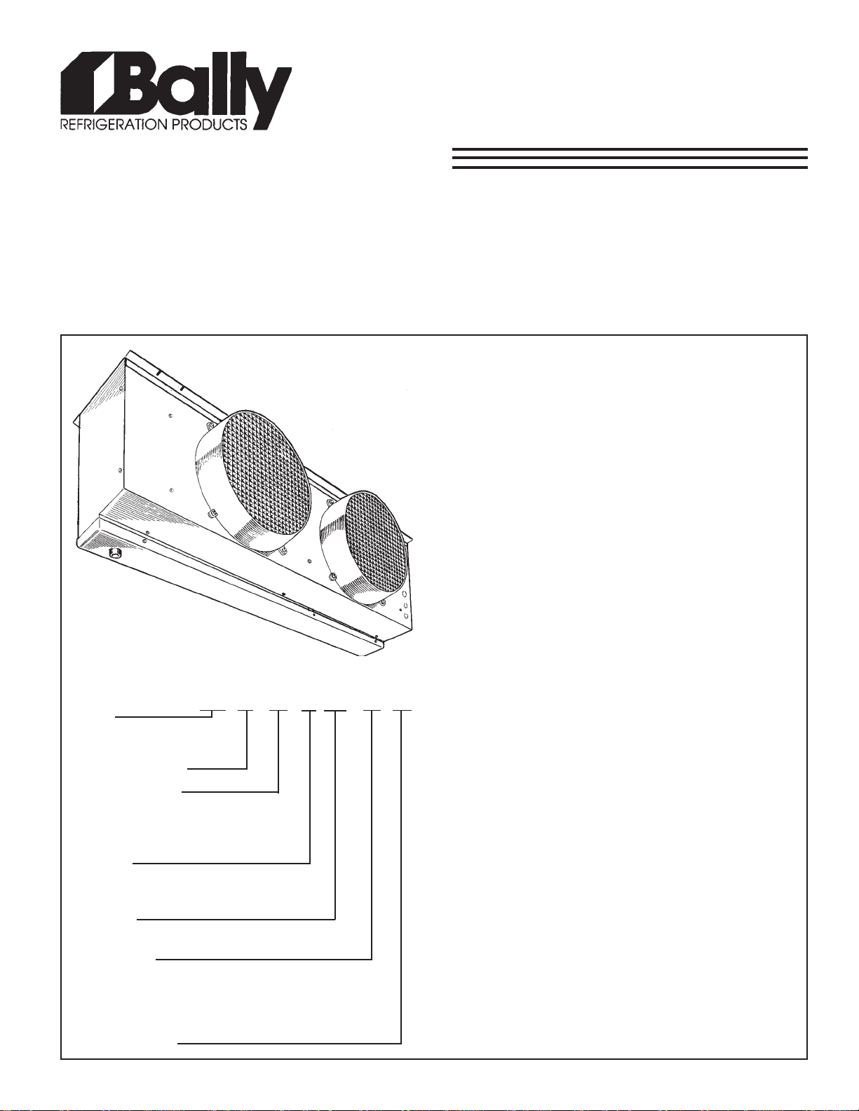
* Heavy gauge textured aluminum cabinet
construction resists scratches/corrosion and
minimizes weight for shipment, installation and
service.
* Attractive and durable high density polyethylene
fan guards with built-in throw boosters.
NOMENCLATURE
BB 1 31 P -A- T4 B
BALLY
MEDIUM PROFILE
UNIT COOLER
NUMBER OF FANS
MBH CAP ACITY A T
°F T .D. (60Hz)
10
SIZE 31 = 31,000 BTUH
OF COOLING
OPTIONS
P = PRE ASSEMBLED REMOTE
S = STANDARD UNIT
DEFROST
A = AIR DEFROST
ELECTRICAL
S2 = 208-230/1/60 S6 = 200-220/1/50
T3 = 208-230/3/60 T4 = 460/3/60
T5 = 575/3/60 T7 = 200-220/3/50
T8 = 380/3/60 T9 = 380-400/3/50
REVISION LEVEL
* 3/8 Tubing coil construction (reduces operating
charge).
* VENTURI-FLO Distributor eliminates need for
distributor nozzle selections.
* Refrigerants R12, R22, R502, R134a, R404A,
R407A, R407B, R407C, R507.
CONTENTS
Nomenclature....................................
Capacity Data.....................................
Electrical Data...................................
Wiring Diagram..................................
Dimensional Data..............................
Pictorial Views...................................
Expansion Valve Selection..............
Application.........................................
Installation.........................................
Inspection..........................................
Location.............................................
Mounting............................................
Drain Line...........................................
Wiring.................................................
System Check....................................
Maintenance.......................................
Service Parts List..............................
Project Information............................
PAGE
Cover
2
2,3
4
5
6
6
7
7
7
7
7
7
7
7
7
Back
Back
Page 2
SPECIFICATIONS
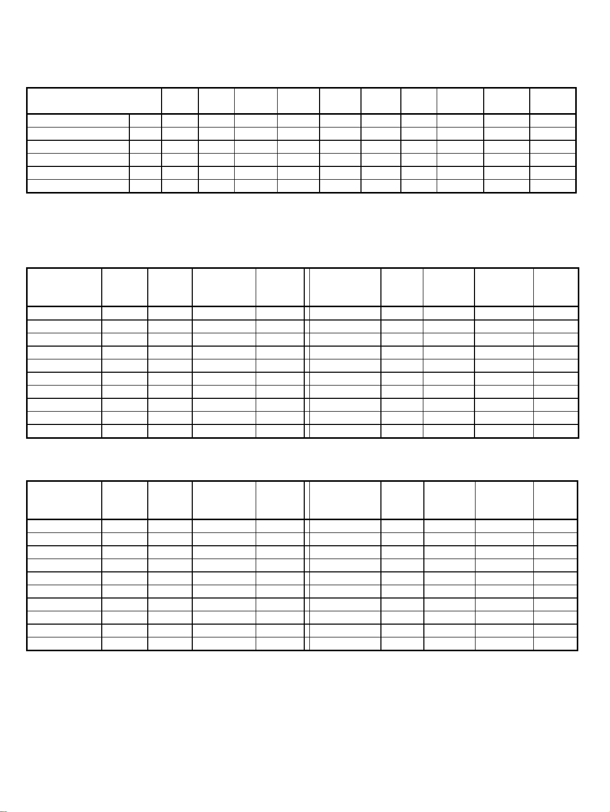
CAPACITY DATA (BTUH)
High Temperature
Model BB
Capacity 1°F T.D. BTUH 2,000 2,500 3,100 3,900 4,700 5,400 6,300 7,400 8,300 9,300
Capacity 10°F T.D. BTUH 20,000 25,000 31,000 39,000 47,000 54,000 63,000 74,000 83,000 93,000
Capacity 15°F T.D. BTUH 30,000 37,500 46,500 58,500 70,500 81,000 94,500 111,000 124,500 139,500
CFM cfm 3,000 4,700 4,550 9,400 9,400 9,100 9,100 13,650 13,650 13,150
Refrigerant Charge* Lbs. 3.4 6.1 9 8.9 11.8 14.9 17.9 17.7 23 26.5
Approx. Shipping Wt Lbs. 160 190 205 350 370 380 390 540 560 580
* R22 at +20°F S.S.T. with coil 30% full
120P-A 125P-A 131P-A 239P-A 247P-A 254P-A 263P-A 374P-A 383P-A 393P-A
ELECTRICAL DATA FAN MOTORS 60HZ
208-230/1/60 208-230/3/60
MODEL
BB120P-A-S2B
BB125P-A-S2B
BB131P-A-S2B
BB239P-A-S2B
BB247P-A-S2B
BB254P-A-S2B
BB263P-A-S2B
BB374P-A-S2B
BB383P-A-S2B
BB393P-A-S2B
FAN
MOTOR
QTY
1 3.3 4.13 15
1 3.3 4.13 15
1 3.3 4.13 15
2 6.6 7.43 15
2 6.6 7.43 15
2 6.6 7.43 15
2 6.6 7.43 15
3 9.9 10.73 15
3 9.9 10.73 15
3 9.9 10.73 15
FAN
FLA
TOTAL
MIN. CIRC.
AMPACITY
(A)
MAX.
FUSE
(AMPS)
MODEL
BB120P-A-T3B
BB125P-A-T3B
BB131P-A-T3B
BB239P-A-T3B
BB247P-A-T3B
BB254P-A-T3B
BB263P-A-T3B
BB374P-A-T3B
BB383P-A-T3B
BB393P-A-T3B
FAN
MOTOR
QTY
FAN FLA
TOTAL
MIN. CIRC.
AMPACITY
(A)
1 2.0 2.5 15
1 2.0 2.5 15
1 2.0 2.5 15
2 4.0 4.5 15
2 4.0 4.5 15
2 4.0 4.5 15
2 4.0 4.5 15
3 6.0 6.5 15
3 6.0 6.5 15
3 6.0 6.5 15
MAX.
FUSE
(AMPS)
460/3/60 575/3/60
FAN
MODEL
MOTOR
QTY
BB120P-A-T4B
BB125P-A-T4B
BB131P-A-T4B
BB239P-A-T4B
BB247P-A-T4B
BB254P-A-T4B
BB263P-A-T4B
BB374P-A-T4B
BB383P-A-T4B
BB393P-A-T4B
1 1.0 1.25 15
1 1.0 1.25 15
1 1.0 1.25 15
2 2.0 2.25 15
2 2.0 2.25 15
2 2.0 2.25 15
2 2.0 2.25 15
3 3.0 3.25 15
3 3.0 3.25 15
3 3.0 3.25 15
All fan motors are 3/4 H.P.
FAN
FLA
TOTAL
MIN. CIRC.
AMPACITY
(A)
MAX.
FUSE
(AMPS)
MODEL
BB120P-A-T5B
BB125P-A-T5B
BB131P-A-T5B
BB239P-A-T5B
BB247P-A-T5B
BB254P-A-T5B
BB263P-A-T5B
BB374P-A-T5B
BB383P-A-T5B
BB393P-A-T5B
- 2 -
FAN
MOTOR
QTY
FAN FLA
TOTAL
MIN. CIRC.
AMPACITY
(A)
1 0.8 1 15
1 0.8 1 15
1 0.8 1 15
2 1.6 1.8 15
2 1.6 1.8 15
2 1.6 1.8 15
2 1.6 1.8 15
3 2.4 2.6 15
3 2.4 2.6 15
3 2.4 2.6 15
MAX.
FUSE
(AMPS)
Page 3
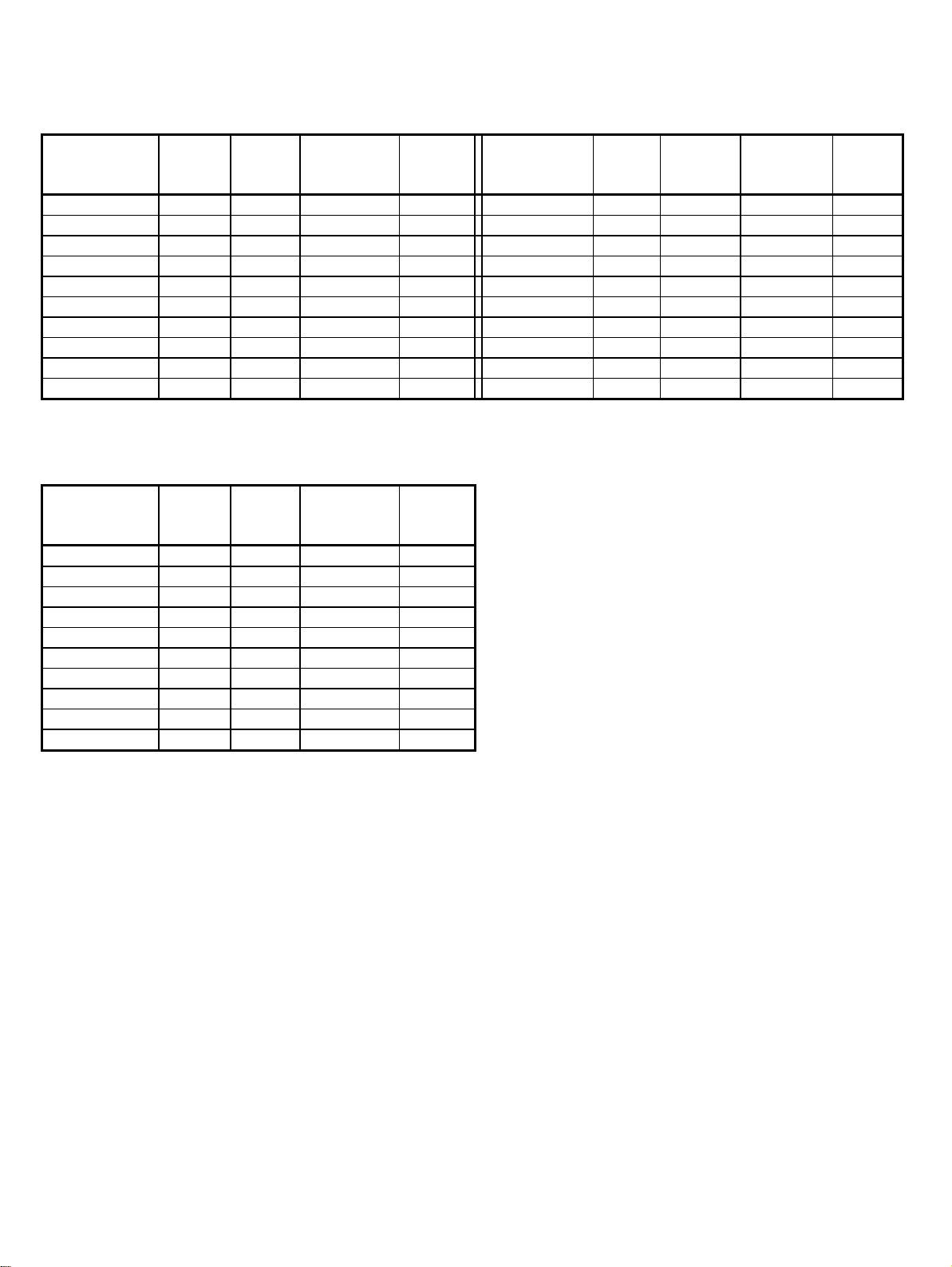
ELECTRICAL DATA FAN MOTORS 50HZ
200-220/1/50 200-220/3/50
MODEL
BB120P-A-S6B
BB125P-A-S6B
BB131P-A-S6B
BB239P-A-S6B
BB247P-A-S6B
BB254P-A-S6B
BB263P-A-S6B
BB374P-A-S6B
BB383P-A-S6B
BB393P-A-S6B
380-400/3/50
MODEL
BB120P-A-T9B
BB125P-A-T9B
BB131P-A-T9B
BB239P-A-T9B
BB247P-A-T9B
BB254P-A-T9B
BB263P-A-T9B
BB374P-A-T9B
BB383P-A-T9B
BB393P-A-T9B
FAN
MOTOR
QTY
1 3.1 3.88 15
1 3.1 3.88 15
1 3.1 3.88 15
2 6.2 6.98 15
2 6.2 6.98 15
2 6.2 6.98 15
2 6.2 6.98 15
3 9.3 10.08 15
3 9.3 10.08 15
3 9.3 10.08 15
FAN
MOTOR
QTY
1 0.8 1.0 15
1 0.8 1.0 15
1 0.8 1.0 15
2 1.6 1.8 15
2 1.6 1.8 15
2 1.6 1.8 15
2 1.6 1.8 15
3 2.4 2.6 15
3 2.4 2.6 15
3 2.4 2.6 15
FAN
FLA
TOTAL
FAN
FLA
TOTAL
MIN. CIRC.
AMPACITY
(A)
MIN. CIRC.
AMPACITY
(A)
MAX.
FUSE
(AMPS)
MAX.
FUSE
(AMPS)
MODEL
BB120P-A-T7B
BB125P-A-T7B
BB131P-A-T7B
BB239P-A-T7B
BB247P-A-T7B
BB254P-A-T7B
BB263P-A-T7B
BB374P-A-T7B
BB383P-A-T7B
BB393P-A-T7B
FAN
MOTOR
QTY
FAN FLA
TOTAL
MIN. CIRC.
AMPACITY
(A)
1 1.7 2.13 15
1 1.7 2.13 15
1 1.7 2.13 15
2 3.4 3.83 15
2 3.4 3.83 15
2 3.4 3.83 15
2 3.4 3.83 15
3 5.1 5.53 15
3 5.1 5.53 15
3 5.1 5.53 15
MAX.
FUSE
(AMPS)
All fan motors are 3/4 H.P.
- 3 -
Page 4

WIRING DIAGRAM
- 4 -
Page 5

DIMENSIONAL DATA
DIMENSIONAL DATA
INCHES (MILLIMETRES)
High Temp Air Defrost Model: 120 125 131 239 247 254 263 374 383 393
Number of Fans 1 1 1 2 2 2 2 3 3 3
Liquid Connection (O.D. Sweat) 5/8
(16)
Suction Connection (O.D. Sweat) 7/8
(22)
5/8
(16)
1 1/8
(29)
5/8
(16)
1 1/8
(29)
- 5 -
5/8
(16)
1 3/8
(35)
7/8
(22)
1 3/8
(35)
7/8
(22)
1 5/8
(41)
7/8
(22)
1 5/8
(41)
7/8
(22)
1 5/8
(41)
7/8
(22)
1 5/8
(41)
7/8
(22)
2 1/8
(54)
Page 6

ELECTRICAL VIEW PIPING VIEW
SUCTION EXTERNAL TX VALVE
TERMINAL BLOCK CONN. EQUALIZER CONN. CONN.
THERMOSTATIC EXPANSION VALVE
SELECTION CHART FOR +35°°F ROOMS AND UP
ALCO VALVE MODEL* SPORLAN VALVE MODEL
MODEL T.D. CAPACITY
MBH
120A 10
15
125A 10
15
131A 10
15
239A 10
15
247A 10
15
254A 10
15
263A 10
15
374A 10
15
383A 10
1583124.5
393A 10
1593139.5
20
30
25
37.5
31
46.5
39
58.5
47
70.5
54
81
63
94.5
74
111
* Where available use the HFESC series valve which includes sweat fittings with a removable/cleanable inlet screen.
Note: Above Selections are based on 100°F Entering Liquid Temperature.
VENTURI - FLO distributor does not require the selection or use of distributor nozzles,
REFRIGERANT
R22
HFES-2-HC
HFES-2 1/2-HC
HFES-2-HC
HFES-3-HC
HFES-2 1/2-HC
HFES-5 1/2-HC
HFES-3-HC
HFES-5 1/2-HC
HFES-5 1/2-HC
HFES-5 1/2-HC
HFES-5 1/2-HC
HFES-8-HC
HFES-5 1/2-HC
HFES-8-HC
HFES-5 1/2-HC
HFES-10-HC
HFES-8-HC
HFES-10-HC
HFES-8-HC
HFES-10-HC
REFRIGERANT
R502/404A/507
HFES-1 1/2-RC
HFES-2-RC
HFES-2-RC
HFES-3 1/2-RC
HFES-3 1/2-RC
HFES-3 1/2-RC
HFES-3 1/2-RC
HFES-5-RC
HFES-3 1/2-RC
HFES-5-RC
HFES-5-RC
HFES-7-RC
HFES-5-RC
HFES-10-RC
HFES-7-RC
HFES-10-RC
HFES-7-RC
HFES-10-RC
HFES-10-RC
TRAE-12-RC
REFRIGERANT
R134a
HFES-1 1/2-MC
HFES-2 1/2-MC
HFES-1 3/4-MC
HFES-4-MC
HFES-2 1/2-MC
HFES-4-MC
HFES-4-MC
HFES-4-MC
HFES-4-MC
HFES-6-MC
HFES-4-MC
HFES-6-MC
HFES-4-MC
HFES-7 1/2-MC
HFES-6-MC
HFES-7 1/2-MC
HFES-6-MC
HFES-11-MC
HFES-7 1/2-MC
HFES-11-MC
REFRIGERANT
R22
EGVE-1 1/2-C
EGVE-3-C
EGVE-2-C
EGVE-3-C
EGVE-3-C
EGVE-3-C
EGVE-3-C
SVE-4-C
EGVE-3-C
SVE-5-C
SVE-4-C
SVE-8-C
SVE-4-C
SVE-8-C
SVE-5-C
SVE-8-C
SVE-8-C
SVE-10-C
SVE-8-C
SVE-10-C
REFRIGERANT
R502/404A/507
EGSE-1 1/2-C
EGSE-2-C
EGSE-2-C
SSE-3-C
EGSE-2-C
SSE-4-C
SSE-3-C
SSE-4-C
SSE-4-C
SSE-6-C
SSE-4-C
SSE-7-C
SSE-4-C
SSE-7-C
SSE-6-C
OSE-9-C
SSE-7-C
OSE-9-C
OSE-7-C
OSE-12-C
REFRIGERANT
R12/R134a
EGJE-1 1/2-C
EGJE-2-C
EGJE-1 1/2-C
SJE-2 1/2-C
EGJE-2-C
SJE-3-C
SJE-2 1/2-C
SJE-5-C
SJE-3-C
SJE-6-C
SJE-5-C
SJE-6-C
SJE-5-C
OJE-6-C
OJE-9-C
OJE-12-C
SJE-6-C
OJE-9-C
OJE-6-C
OJE-9-C
- 6 -
Page 7

APPLICATION
High Temp Unit Coolers are designed for use with R12, R22,
R134a, R404A, R407A/B/C, R507 or R502 refrigerants.
At room temperatures above 34°F and evaporating temps no
lower than 27°F the air flowing through the coil will accomplish
the defrost. Temperatures of 34°F and below (to -40°F) require
positive defrosting. (either Electric or Hot Gas).
The coil must not be exposed to any abnormal atmospheric or
acidic environments. This may result in corrosion to the cabinet
and possible coil failure (leaks). (Consult manufacturer for
optional baked on phenolic protective coatings).
INSTALLATION
The installation and start-up of Unit Coolers should only be
performed by qualified refrigeration mechanics.
This equipment should be installed in accordance with all
applicable codes, ordinances and local by-laws.
MOUNTING
Mounting brackets with 7/16” dia holes are provided for flush
mounting to the ceiling. For details refer to dimensional data on
page 5. Ensure adequate clearance (at least 24”) is provided
behind the coil as well as each side (to enable access to the
electrical and refrig. compartments).
Ensure that the ceiling is level since the drain pan has been
sloped for drainage during the defrost cycle.
DRAIN LINE
The drain line should be run from the drain connection, sloping
at least 4” per foot. A trap outside the room will prevent warm air
from entering through the tubing. Connection should be made
to proper drainage facilities that comply with local regulations.
Ensure that the drain pan has sufficient slope for proper
drainage (prevention of ice build up/blockage in pan).
INSPECTION
Inspect all equipment before unpacking for visible signs of
damage or loss. Check shipping list against material received
to ensure shipment is complete.
IMPORTANT: Remember, you, the consignee, must make any
claim necessary against the transportation company. Shipping
damage or missing parts, when discovered at the outset, will
prevent later unnecessary and costly delays.
If damage or loss during transport is evident, make claim to
carrier, as this will be their responsibility, not the
manufacturer’s.
Should carton be damaged, but damage to equipment is not
obvious, a claim should be filed for “concealed damage” with
the carrier.
IMPORTANT: The electrical characteristics of the unit should be
checked at this time to make sure they correspond to those
ordered and to electrical power available at the job site.
Save all shipping papers, tags and instruction sheets for
reference by installer and owner.
LOCATION
The unit location in the room should be selected to ensure
uniform air distribution throughout the entire space to be
refrigerated. Be sure that the unit does not draw air in, or blow
directly out, through an opened door and that the product does
not obstruct the free circulation of air. Allow a minimum of 24”
clearance at each end and behind the unit.
The Unit Coolers draw air through the coil and discharge air
from the fan side.
PIPING
Refrigerant line sizes are important and may not be the same
size as the coil connections. (depends on the length of run) If in
doubt, consult “Recommended refrigerant line sizes” charts.
(Engineering Manuals or other recognized sources of
information).
WIRING
Wire system in accordance with governing standards and local
codes. See data and wiring diagrams on pages 2 and 3 for
wiring arrangement. Electrical wiring is to be sized in
accordance with minimum ampacity rating.
SYSTEM CHECK
Before Start-Up:
1. All wiring should be in accordance with local codes.
2. Refrigerant lines should be properly sized.
3. Off-cycle defrost systems should include a liquid line
solenoid valve.
4. Thorough evacuation and, dehydration has been performed.
5. The suction, discharge, and receiver service valves must be
open.
6. The system should include a liquid line drier moisture
indicator and suction filter.
7. Pour enough water into the drain pan to allow a good check
on drainage and seal the trap.
After Start-Up:
1. Check the compressor oil level to ensure the correct oil
charge.
2. Be sure that the expansion valve is properly set to provide
the correct amount of superheat.
3. Heavy moisture loads are usually encountered when starting
the system for the first time.
4. Check for proper evaporator fan blade rotation.
Consideration should be given to the coil location in order to
minimize the piping run length to the condensing unit and floor
drain.
MAINTENANCE
The unit should be periodically inspected for any dirt or build-up
on the fin surface and cleaned if necessary with a soft whisk or
brush.
- 7 -
Page 8

SERVICE PARTS LIST
01/10/05
06/1/032-802
06/3/032-802
06/3/064
06/3/575
05/1/022-002
05/3/022-002
05/3/004-083
NAF
SEDALB
O
81"02
O
32"02
SDRAUGNAF
po(eriWlateM
tuNnrocA
ZHO6-SROTOMNAF
ZH05-SROTOMNAF
edalB-4hctiP
edalB-4hctiP
)dradnats(retsooBworhTdedluoM
)lanoit
TNUOMROTOM
KCOLBLANIMRET
SLEDOM
LLA
LLA
LLA
LLA
SLEDOM
LLA
LLA
LLA
SLEDOM
A021
LLA
LLA
LLA
LLA1305401
LLA710540
)A021TPECXE(LLA
SLEDOM
1
#TRAP
2305401
3305401
4305401
5401
530
#TRAP
2305401
3305401
4305401
#TRAP
8658401
5115401
#TRAP
9805401
1905401
8315401
SERVICE LOG
ETADSTNEMMOC
PROJECT INFORMATION
metsyS
rebmuNledoM pU-tratSfoetaD
rebmuNlaireS rotcartnoCecivreS
tnaregirfeRenohP
ylppuSlacirtcelExaF
DISTRIBUTED BY:
General Sales, PGeneral Sales, P
General Sales, P
General Sales, PGeneral Sales, P
135 Little Nine Drive, Morehead City135 Little Nine Drive, Morehead City
135 Little Nine Drive, Morehead City
135 Little Nine Drive, Morehead City135 Little Nine Drive, Morehead City
252-240-2829 • 1-800-24-BALL252-240-2829 • 1-800-24-BALL
252-240-2829 • 1-800-24-BALL
252-240-2829 • 1-800-24-BALL252-240-2829 • 1-800-24-BALL
e-mail: ballysales@ballyrefboe-mail: ballysales@ballyrefbo
e-mail: ballysales@ballyrefbo
e-mail: ballysales@ballyrefboe-mail: ballysales@ballyrefbo
Due to Manufacturer’s policy of continuous product improvement, the Manufacturer reserves the right to make changes without notice.
arar
ts & Serts & Ser
ar
ts & Ser
arar
ts & Serts & Ser
vice Manufacturing & Engineeringvice Manufacturing & Engineering
vice Manufacturing & Engineering
vice Manufacturing & Engineeringvice Manufacturing & Engineering
xx
x
xx
, NC 28557, NC 28557
, NC 28557
, NC 28557, NC 28557
Y • FY • F
AX: 252-240-0384AX: 252-240-0384
Y • F
AX: 252-240-0384
Y • FY • F
es.com • wwwes.com • www
es.com • www
es.com • wwwes.com • www
AX: 252-240-0384AX: 252-240-0384
.ballyrefbo.ballyrefbo
.ballyrefbo
.ballyrefbo.ballyrefbo
xx
es.comes.com
x
es.com
xx
es.comes.com
C
US
 Loading...