

Ballu KFR-3601GW, KFR-3502BPE, KFR-3601BPE, KFR-4001GW, KFR-4001BPE Service Manual
...
-
KFR 3601GW/BPE
KFR- 4001GW/BPE
KFR- 3502GW/BPE
SERVICE
MANUAL
SPLIT TYPE INVERTER AIR CONDITIONER
CONTENTS
1.PART NAMES AND FUNCTIONS...................
2.SPECIFICATION............................................
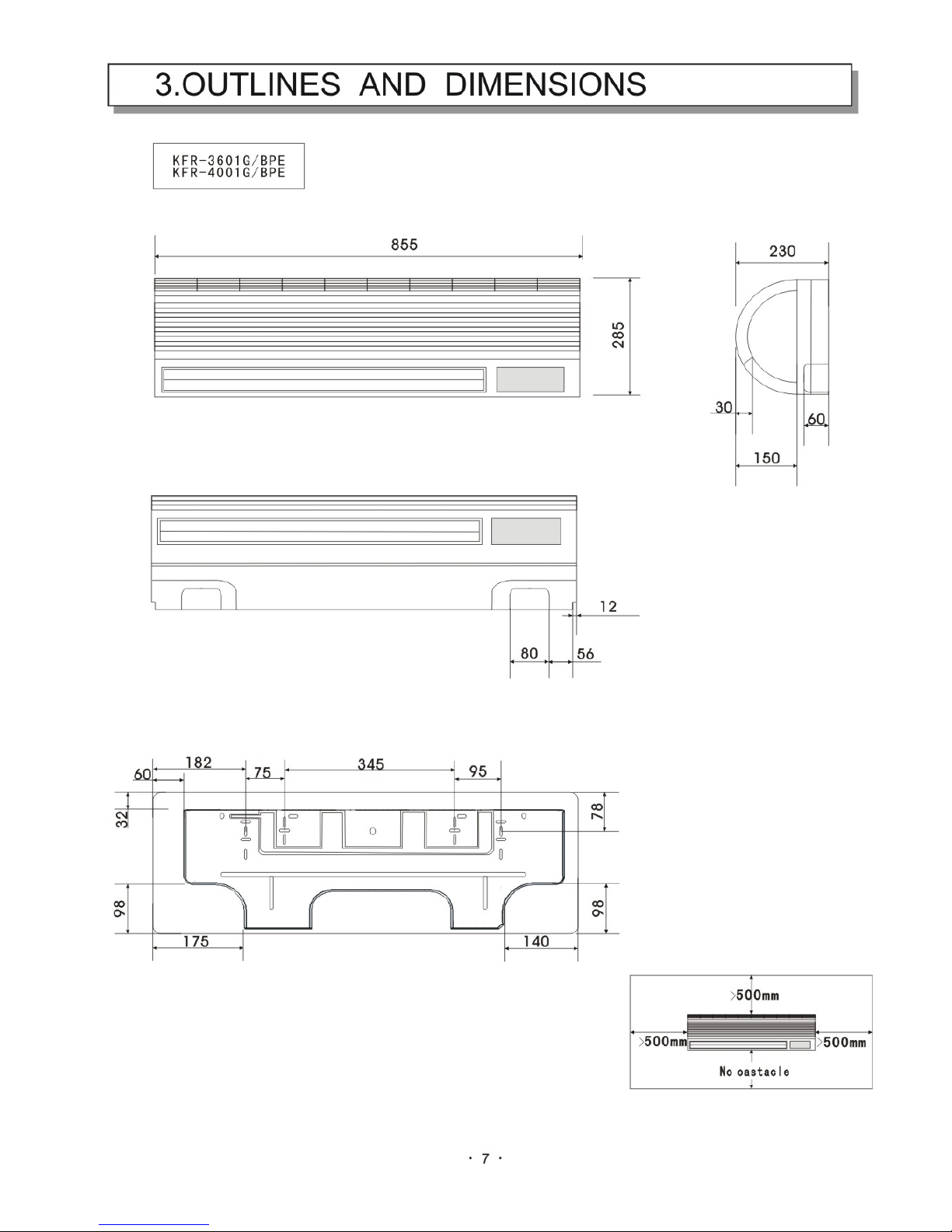
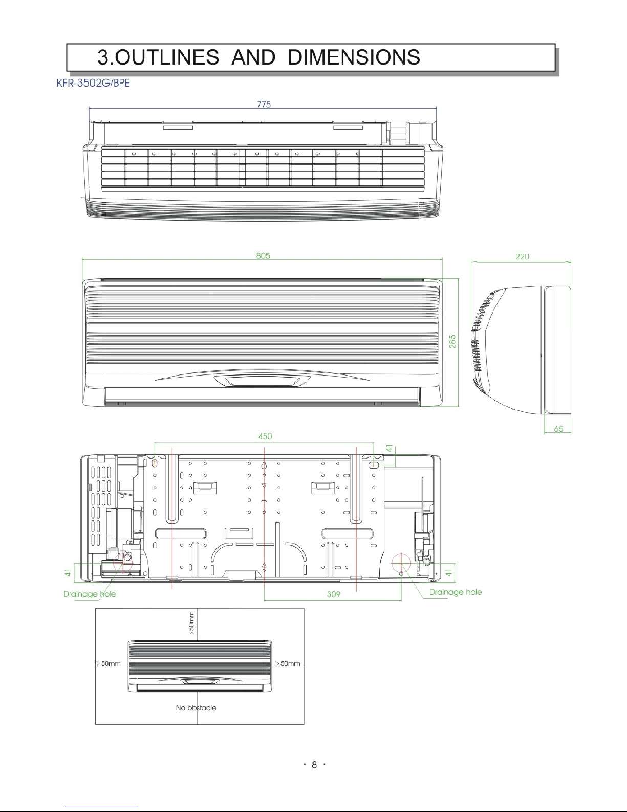
3.OUTLINES AND DIMENSIONS.......................
4.WIRING DIAGRAM.........................................
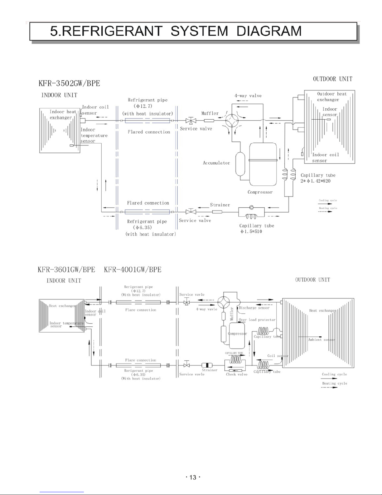
5.REFRIGERANT SYSTEM DIAGRAM...............
6.PERFORMANCE DATA..................................
7.CONTROL MODE ..........................................
8.TROUBLESHOOTING....................................
9.SERVICE FLOW CHART...............................
10.SENSOR PARAMETER................................
11.DISASSEMBLY INSTRUCTIONS...................
12.PARTS LIST.................................................
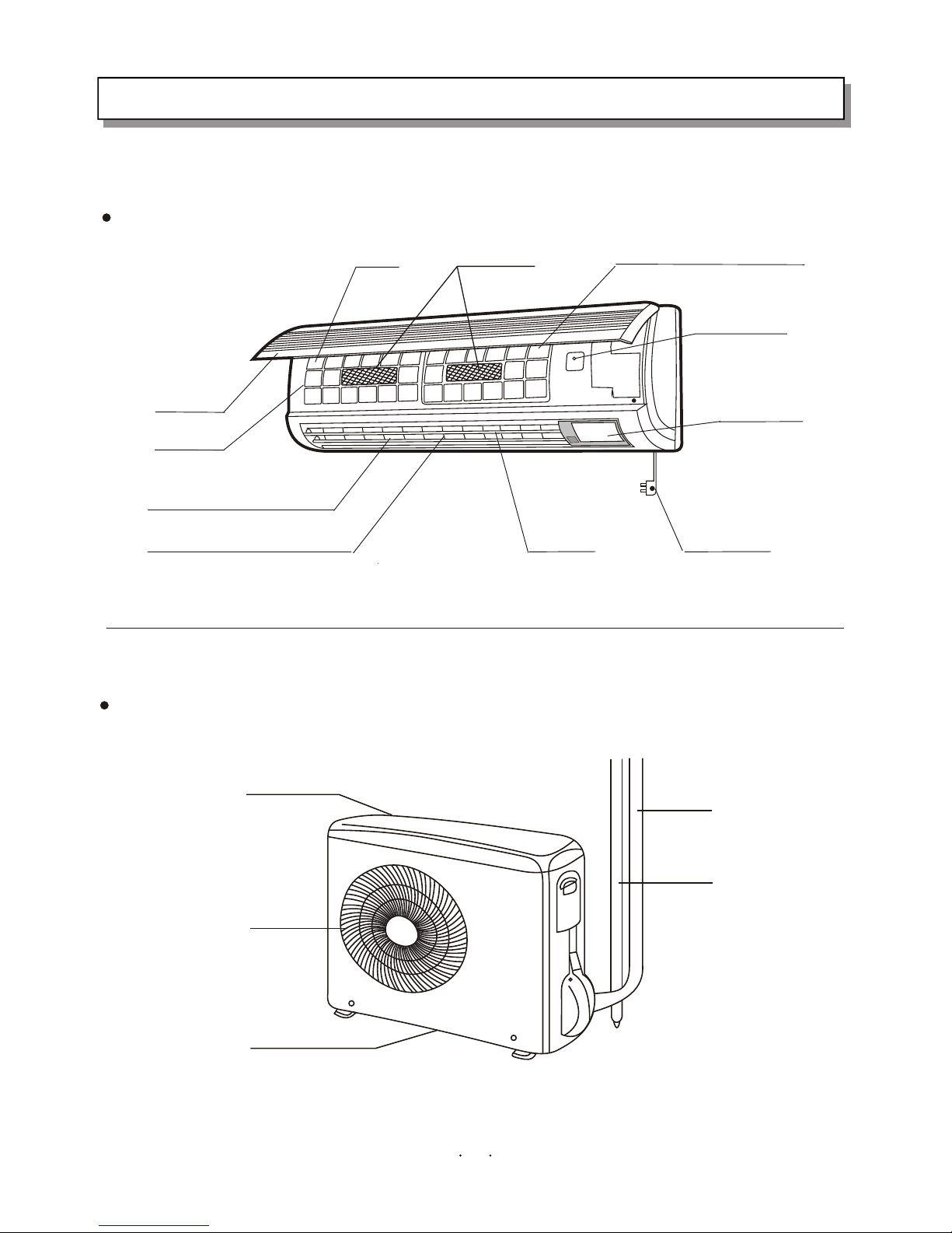
1. PART NAMES AND FUNCTIONS
Vertical Vane
INDOOR UNIT
OUTDOOR UNIT
Tubes and cable
Drainage hose
Drainage hole (bottom)
Air outlet
Air inlet (rear and side)
1
KFR-3601W/BPE
KFR-4001W/BPE
KFR-3601G/BPE
KFR-4001 /BPEG
Switch button
VFD screen
Power plug
Air outlet
Air inlet grille
Front cover
Air filter Air fresh filter
Indoor coil sensor(inside)
Horizontal Vane
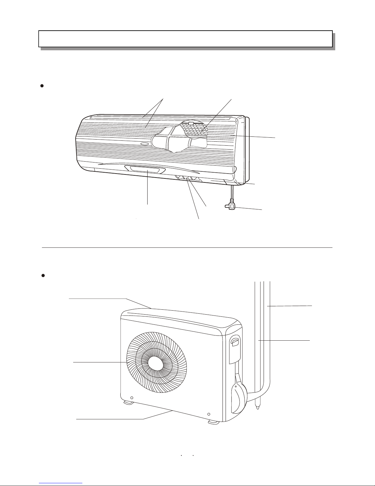
Tubes and cable
Drainage hose
Air inlet (rear and side)
Air outlet
Drainage hole(bottom)
Air inlet
Air filter
Front panel
Horizontal Vane
Power plug
Air outlet
Vertical vane
Color display screen
INDOOR UNIT
KFR-3502G/BPE
KFR-3502G/BPE
OUTDOOR UNIT
2
1. PART NAMES AND FUNCTIONS
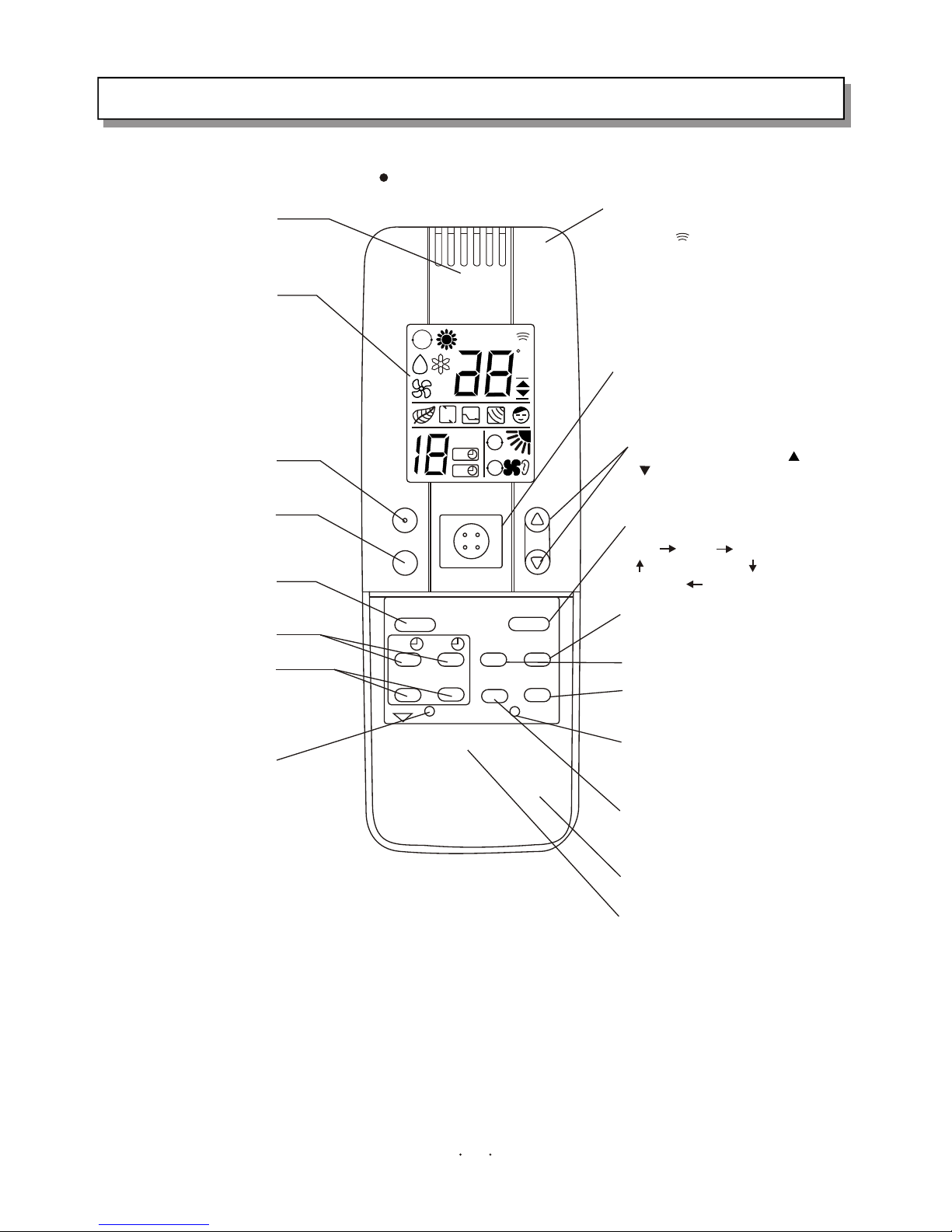
REMOTE CONTROL UNIT
1Сʱ
AA
T.SETTIN GT.SETTIN G
C
A
A
A
HOUR
ON
OFF
H.P.
ON/OFF
TEMP.
SLEEP
FLAP
ON
OFF
SET
CLR
SENSOR
BATTERY
FAN/MUTE
SOFT
RESET
TEMP.DISP
ATR EX.
MODE
Sensor
Testing the ambient temperature
of the remote control unit
LCD
Displaying the running condition.
Hi-power running button
Sleep button
Press the button, the appliance enter
sleep mode.
Flap
Up-down adjustment
Timer on/off button
Setting the time of appliance on/off.
Set/cancel timer button
Set or cancel the time of appliance
on/off.
A/C sensor button
Press the button if the remote
control unit is liable to be affected by
the heat resource, such as electric
blanket, radiator or sunlight, this will
use the sensor of indoor unit, the
symbol will appear on the LCD.
Transmitter
Transmitting signals to the indoor unit,
the symbol will appear on the top of
LCD.
On/Off button
Press the button to run, press again
to cease.
Temperature setting button
Press the button marked " "or
the temperature.
Air exchange button
When this function works, the air
can be keep fresh.
Mode selection button
Auto heating dehumidification
Fan cooling
Fan speed selection button
Temperature displaying button
setting the temperature in the screen
of indoor unit
Reset button
Press the button after batteries are
loaded and indication appears on
LCD.
Duel energy-saving
This function can be used for
Restricting the max. electric current
by control software.
Sliding cover
Battery compartment
" " to increase or decrease
3
KFR-3601G/BPE
KFR-4001 /BPEG
1. PART NAMES AND FUNCTIONS
REMARK: The remote controller transmits signal to indoor unit at 3 minutes intervals. If the indoor unit
has not received the signal for more than 10 minutes due to remote controller missing or other reason,
the sensor on indoor unit will be used for detecting indoor temperature automatically. Here, ambient
temperature of remote controller is likely to slightly different from that detecting by the indoor unit,
temperature will be compensated automatically. When the remote controller is missing or the batteries
are exhausted, please use the temporary switch.
AA
T.SETTINGT.SETTING
C
A
A
A
HOUR
ON
OFF
H.P.
ON/OFF
TEMP.
SLEEP
FLAP
ON
OFF
SET
CLR
SENSOR
BATTERY
FAN/MUTE
SOFT
RESET
MODE
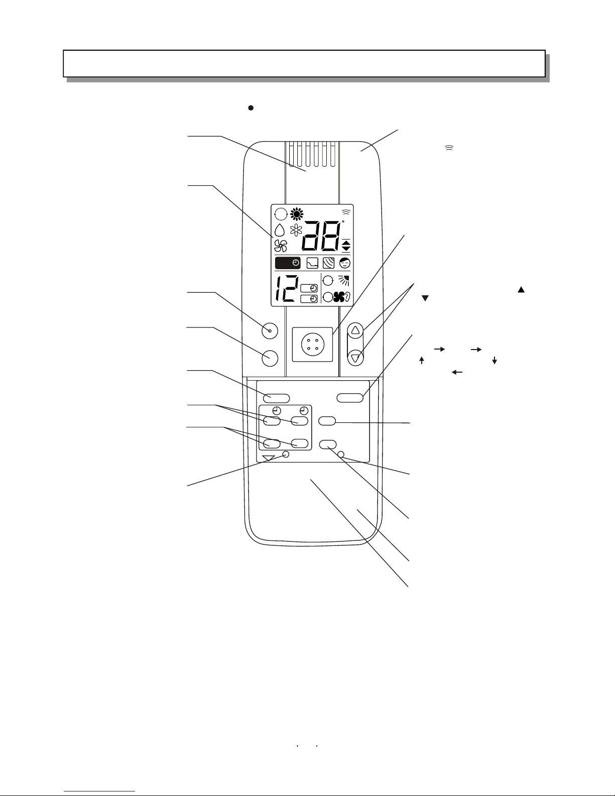
Sensor
Testing the ambient temperature
of the remote control unit
LCD
Displaying the running condition.
Hi-power running button
Sleep button
Press the button, the appliance enter
sleep mode.
Flap
Up-down adjustment
Timer on/off button
Setting the time of appliance on/off.
Set/cancel timer button
Set or cancel the time of appliance
on/off.
A/C sensor button
Press the button if the remote
control unit is liable to be affected by
the heat resource, such as electric
blanket, radiator or sunlight, this will
use the sensor of indoor unit, the
symbol will appear on the LCD.
Transmitter
Transmitting signals to the indoor unit,
the symbol will appear on the top of
LCD.
On/Off button
Press the button to run, press again
to cease.
Temperature setting button
Press the button marked " "or
" " to increase or decrease
the temperature.
Mode selection button
Auto heating dehumidification
Fan cooling
Fan speed selection button
Reset button
Press the button after batteries are
loaded and indication appears on
LCD.
Duel energy-saving
This function can be used for
Restricting the max. electric current
by control software.
Sliding cover
Battery compartment
1 HOUR
REMOTE CONTROL UNIT
KFR-3502G/BPE
4
1. PART NAMES AND FUNCTIONS
REMARK: The remote controller transmits signal to indoor unit at 3 minutes intervals. If the indoor unit
has not received the signal for more than 10 minutes due to remote controller missing or other reason,
the sensor on indoor unit will be used for detecting indoor temperature automatically. Here, ambient
temperature of remote controller is likely to slightly different from that detecting by the indoor unit,
temperature will be compensated automatically. When the remote controller is missing or the batteries
are exhausted, please use the temporary switch.
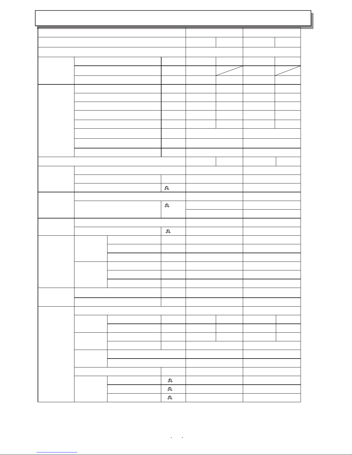
2.SPECIFICATION
5
Model KFR-3601GW/BPE KFR-4001GW/BPE
Function Cooling Heating Cooling Heating
Power supply a.c 220V~ 50Hz a.c 220V~ 50Hz
Capacity KW
3.6 5.0 4.0 6.0
Dehumidification
l /h
1.5 1.8
Capacity
Air flow m3/h
540 650 630 680
Power outlet A
16 16 16 16
Running current A
6.35 7.8 8.0 11.5
Power input W
1.34 1.58 1.54 2.14
Auxiliary heater A(KW)
----- ----- ----- -----
Power factor %
90 90 90 90
Starting current A
17 17
Compressor motor current A
6.2 6.2
Electrical
data
Fan motor current A
0.2 0.2
Coefficient of performance(C.O.P)
2.68 3.16 2.6 2.8
Model
SGZ20EG2UY SGZ20EG2UY
Output W
1100 1100
Compressor
Winding resistance (at20 )
1.05 1.05
Model
YYW16-4-411 YYW16-4-411
340 ( main) 340 ( main)
Indoor
fan motor
Winding resistance (at20 )
395(assisitant) 395(assisitant)
Model
UE6T-C41A4 UE6T-C41A4
Outdoor
fan motor
Winding resistance (at20 )
151.4 151.4
Width mm
860 860
Height mm 285 285
Indoor unit
Depth mm 235 235
Width mm 800 800
Height mm 555 555
Dimensions
Outdoor unit
Depth mm 260 260
Indoor unit kg 11.5 11.5 Weigh t
Outdoor unit kg 39.0 39.0
Air direction 6 6
Indoor unit dB 39 40 42 43 Sound lever
(Hi)
Outdoor unit dB 48 49 48 49
Indoor unit rpm 1100 1200 1220 1250 Fan speed
(Hi)
Outdoor unit rpm 680 680
Indoor unit 4 4 Fan speed
regulator
Outdoor unit 3 3
Refrigerant filling capacity(R-22) kg 1.10 1.18
RT1(at25 ) k 58 58
RT2(at25 ) k 5.3 5.3
Special
remarks
Thermitstor
RT3(at25 ) k 5 5
NOTE :Test conditions
Cooling : Idoor DB27 / WB19 , Outdoor DB35 / WB24
Heating: Indoor DB20 / WB15 , Outdoor DB7 / WB 6
°Ñ
°Ñ
°Ñ
°Ñ °Ñ
°Ñ
°Ñ
°Ñ
°Ñ
°Ñ
°Ñ
°Ñ
°Ñ
°Ñ
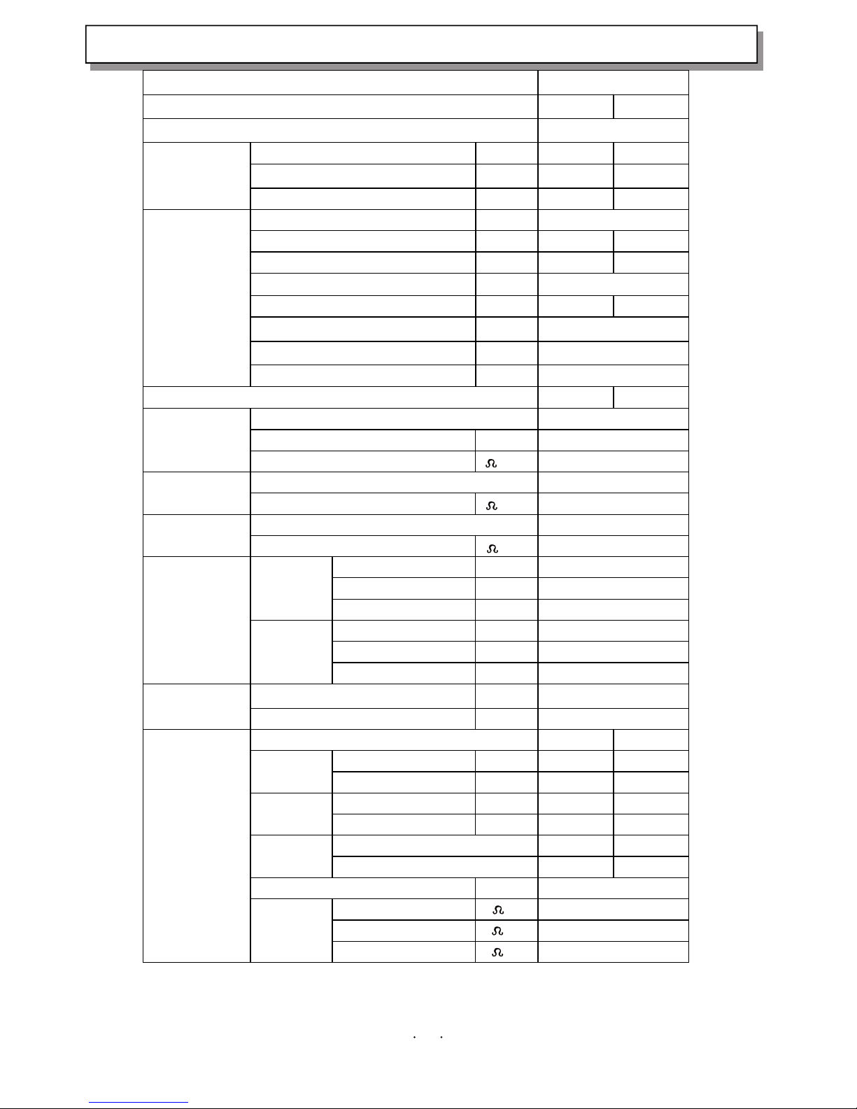
2.SPECIFICATION
6
Model KFR-3502GW/BPE
Function Cooling Heating
Power supply a.c220 50Hz
Capacity KW 3.5 4.8
Dehumidification
l /h
1.8 ——
Capacity
Air flow m3/h 540 640
Power outlet A 16
Running current A 6.5 10.0
Power input W 7.8 12.0
Auxiliary heater A(KW) ——
Power factor % 90 90
Starting current A 20
Compressor motor current A 7.2
Electrical data
Fan motor current A 0.2
Coefficient of performance(C.O.P) 2.7 3.0
Model SHV130FGEC
Output W 650
Compressor
Winding resistance (at20 ) 0.87
Model YZW16W-4-411 Indoor
fan motor
Winding resistance (at20 ) KFR-3601GW/BPE
Model UE6T-C41A4 Outdoor
fan motor
Winding resistance (at20 ) 151.4
Width mm 285
Height mm 220
Indoor unit
Depth mm 805
Width mm 316
Height mm 555
Dimensions
Outdoor unit
Depth mm 867
Indoor unit kg 9.5 Weigh t
Outdoor unit kg 39
Air direction 6 6
Indoor unit dB 39/30 39/33 Sound lever
(Hi)
Outdoor unit dB 48/41 48/41
Indoor unit rpm 1180 1230 Fan speed
(Hi)
Outdoor unit rpm 750 750
Indoor unit 4 4 Fan speed
regulator
Outdoor unit 3 3
Refrigerant filling capacity(R-22) kg 1.15
RT1(at25 ) k 58
RT2(at25 ) k 5.3
Special remarks
Thermitstor
RT3(at25 ) k 5
NOTE :Test conditions
Cooling : Idoor DB27 / WB19 Outdoor DB35 / WB24
Heating: Indoor DB20 / WB15 Outdoor DB7 / WB 6
°Ñ
°Ñ
°Ñ
°Ñ
°Ñ
°Ñ
°Ñ
°Ñ
°Ñ
°Ñ
°Ñ
°Ñ
°Ñ
°Ñ
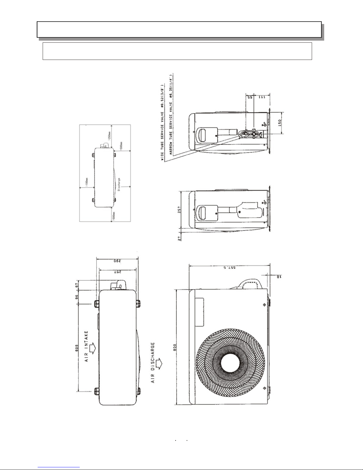
5.REFRIGERANT SYSTEM DIAGRAM3.OUTLINES AND DIMENSIONS
KFR-3601W/BPE KFR-4001W/BPE KFR-3502W/BPE
9
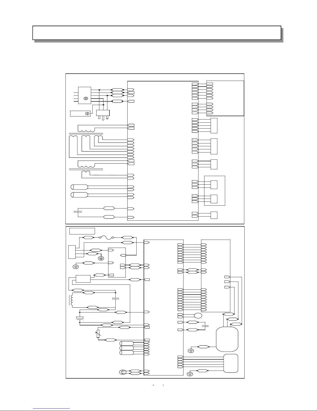
4.WIRING DIAGRAM
ELECTRICAL WIRING DIAGRAM
0
1
2
3
4
(L)
AC IN1
AC OUT1
ACIN2(CN06.2)
+5V(CN01.1)
GND(CN01.2)
CS(CN01.3)
SO(CN01.4)
CLK(CN01.5)
REMOTE(CN01.6)
BRIGHT(CN02.1)
-27V(CN02.2)
4.6B(CN02.3)
4.6A(CN02.4)
+5V(CN08.1)
GND(CN08.2)
CS(CN08.3)
SO(CN08.4)
SCK(CN08.5)
REMOTE(CN08.6)
BRIGHT(CN02.1)
-27V(CN02.2)
4.6B(CN02.3)
4.6A(CN02.4)
FLAPI(CN16.1)
FLAPI(CN16.2)
FLAPI(CN16.3)
FLAPI(CN16.4)
FLAPI(CN16.5)
FLAP2(CN17.1)
FLAP2(CN17.2)
FLAP2(CN17.3)
FLAP2(CN17.4)
FLAP2(CN17.5)
VCC(CN09.1)
GND(CN09.2)
VEN(CN09.3)
FAN(CN07.1)
FAN(CN07.2)
FAN(CN07.3)
+5V(CN11.1)
PH(CN11.2)
GND(CN11.3)
SW(CN15.1)
GND(CN15.2)
SI(CN06.1)
TRANSE(CN04.1)
TRANSE(CN04.2)
TRANSE(CN05.1)
TRANSE(CN05.2)
TRANSE(CN10.1)
TRANSE(CN10.3)
CAP(CN06.1)
CAP(CN06.2)
4.6A(CN01.1)
MID(CN01.2)
4.6B(CN01.3)
9V(CN01.4)
9V(CN01.5)
AC22V(CN01.6)
AC22V(CN01.7)
(L)
(N)
LEN
(SI)
ROOM(CN20.1)
ROOM(CN20.2)
COIL(CN19.1)
COIL(CN19.2)
1
2
3
4
5
1
2
3
4
5
1
2
3
1
2
3
1
2
3
1
2
TERM.PANEL
CONTROL BOARD
EVAP.
POWER TRAN.
POWER TRAN.
POWER WIRE
INDOOR SENSOR
EVAP. SENSOR
FAN CAP.
ELECTRICAL WIRING DIAGRAM
INDICATOR BOARD
STEP. MOTOR 1
STEP. MOTOR 2
AIR EX. FAN
FAN MOTOR
PHASE TEST
POWER SWITCH
BRN
BLK
WHT
RED
BLK
BLK
VUPC(CN12.1)
VUP1(CN12.2)
VVPC(CN12.4)
VVP1(CN12.5)
VWPC(CN12.7)
VWP1(CN12.8)
VNC(CN12.10)
VN1(CN12.11)
VUPC(CN15.1)
VUP1(CN15.2)
VVPC(CN15.4)
VVP1(CN15.5)
VWPC(CN15.7)
VWP1(CN15.8)
VNC(CN15.10)
VN1(CN15.11)
SI(CN09)
IN2
IN1
E
OUT1
OUT2
OUT3
AC
AC
++
PTC
AC IN1(CN04)
AC IN2(CN05)
DC OUT1(CN11)
DC OUT2(CN01)
P(CN07)
N(CN06)
W(CN03)
V(CN04)
U(CN05)
AC OUT1(CN03)
VFC(CN05.1)
GND(CN05.2)
+5V(CN05.3)
Z(CN05.4)
Y(CN05.5)
X(CN05.6)
W(CN05.7)
V(CN05.8)
U(CN05.9)
VFC(CN18.1)
GND(CN18.2)
+5V(CN18.3)
Z(CN18.4)
Y(CN18.5)
X(CN18.6)
W(CN18.7)
V(CN18.8)
U(CN18.9)
DC IN1(CN02)
SV(CNI0.1)
SV(CNI0.2)
FAN CAP(CN06.1)
DC IN2(CN07)
PTC
FAN CAP(CN06.2)
PTC
GAIKI(CN17.1)
GAIKI(CN17.2)
COIL(CN13.1)
COIL(CN13.2)
COMP(CN16.1)
COMP(CN16.2)
C(CN08.1)
AC(CN08.2)
H(CN08.3)
M(CN08.4)
L(CN08.5)
THERMO(CN12.1)
THERMO(CN12.2)
RST
EARTH
C
AC
H
M
L
EARTH
1
2
3
4
+
_
OUTDOOR UNIT
FUSE
FIL. BOARD
TERM. PANEL
REC. BRIDGE
INDUCTOR
CAP.
ELEC. CAPACITOR
OUTDOOR SENSOR
CONDENSOR SENSOR
DISCHARGE SENSOR
OLP
ELECTRICAL WIRING DIAGRAM
CONTROL BOARD IPM BOARD
4-WAY VALVE
FAN CAP.
COMPRESSOR
FAN MOTOR
BLK BLK
BLK
WHT
WHT
WHT
RED
WHT
YEL/GRN
YEL/GRN
YEL/GRN
YEL/GRN
YEL
YEL
ORG
ORG
ORG
BLK
BLK
BRN
RED
WHT
BLU
BLK
BLU
YEL
YEL
RED
RED
BLU
10
KFR-3601GW/BPE
KFR-4001 /BPEGW
ELECTRICAL WIRING DIAGRAM
0
1
2
3
4
(L)
L IN
L OUT1
ACIN2(CN03.2)
+5V(CN01.1)
GND(CN01.2)
CS(CN01.3)
SO(CN01.4)
CLK(CN01.5)
REMOTE(CN01.6)
SW(CN01.7)
-27V(CN02.1)
4.6B(CN02.2)
4.6A(CN02.3)
+5V(CN08.1)
GND(CN08.2)
CS(CN08.3)
SO(CN08.4)
SCK(CN08.5)
REMOTE(CN08.6)
SW(CN08.7)
-27V(CN02.2)
4.6B(CN02.3)
4.6A(CN02.4)
FLAP2(CN17.1)
FLAP2(CN17.2)
FLAP2(CN17.3)
FLAP2(CN17.4)
FLAP2(CN17.5)
FAN(CN07.1)
FAN(CN07.2)
FAN(CN07.3)
+5V(CN11.1)
PH(CN11.2)
GND(CN11.3)
SI(CN03.1)
TRANSE(CN04.1)
TRANSE(CN04.2)
4.6A(CN01.1)
MID(CN01.2)
4.6B(CN01.3)
9V(CN01.4)
9V(CN01.5)
AC22V(CN01.6)
AC22V(CN01.7)
(L)
(N)
LEN
(SI)
ROOM(CN20.1)
ROOM(CN20.2)
COIL(CN19.1)
COIL(CN19.2)
1
2
3
4
5
1
2
3
1
2
3
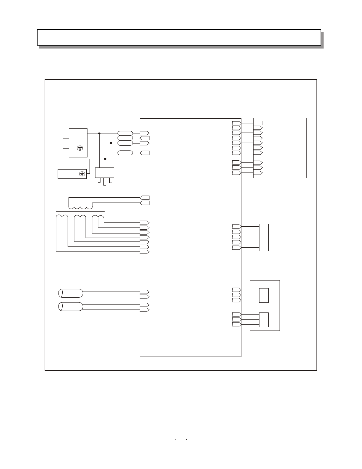
ELECTRICAL WIRING DIAGRAM
TERM.PANEL
CONTROL BOARD
INDICATOR BOARD
EVAP.
POWER TRAN.
POWER WIRE
STEP MOTOR
FAN MOTOR
PHASE TEST
INDOOR SENSOR
EVAP. SENSOR
BRN
BLK
WHT
RED
KFR-3502G/BPE
11
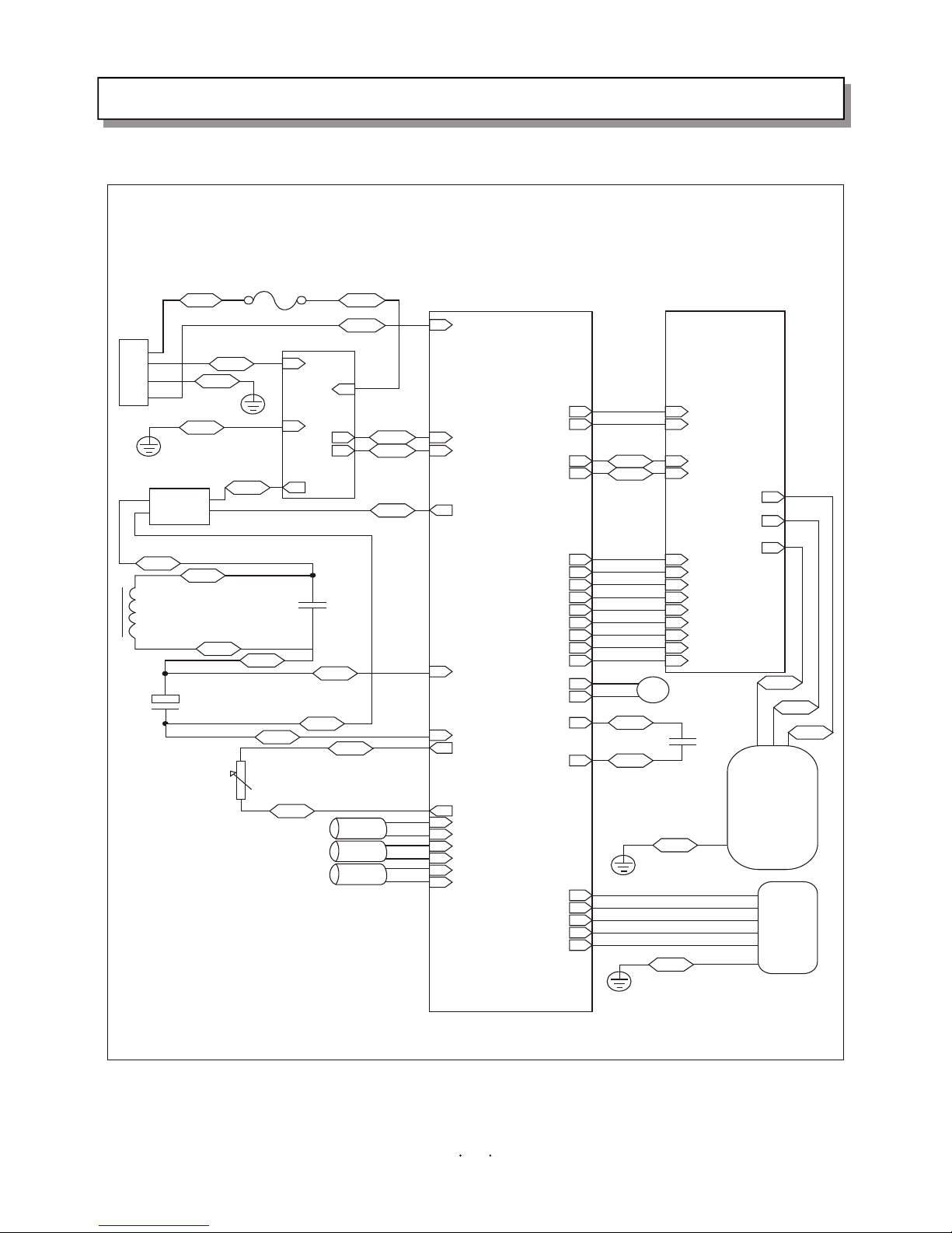
4.WIRING DIAGRAM
VNC(CN12.10)
VN1(CN12.11)
VNC(CN15.10)
VN1(CN15.11)
SI(CN09)
IN2
IN1
E
OUT1
OUT2
OUT3
YEL/GRN
AC
AC
++
PTC
AC IN1(CN04)
AC IN2(CN05)
DC OUT1(CN11)
DC OUT2(CN01)
P(CN07)
N(CN06)
W(CN03)
V(CN04)
U(CN05)
AC OUT1(CN03)
VFC(CN05.1)
GND(CN05.2)
+5V(CN05.3)
Z(CN05.4)
Y(CN05.5)
X(CN05.6)
W(CN05.7)
V(CN05.8)
U(CN05.9)
VFC(CN18.1)
GND(CN18.2)
+5V(CN18.3)
Z(CN18.4)
Y(CN18.5)
X(CN18.6)
W(CN18.7)
V(CN18.8)
U(CN18.9)
DC IN1(CN02)
SV(CNI0.1)
SV(CNI0.2)
FAN CAP(CN06.1)
DC IN2(CN07)
PTC
FAN CAP(CN06.2)
PTC
GAIKI(CN17.1)
GAIKI(CN17.2)
COIL(CN13.1)
COIL(CN13.2)
COMP(CN16.1)
COMP(CN16.2)
C(CN08.1)
AC(CN08.2)
H(CN08.3)
M(CN08.4)
L(CN08.5)
RST
EARTH
C
AC N
H
M
L
EARTH
1
2
3
4
+
_
FUSE
TERM. PANEL
REC. BRIDGE
CONTROL BOARD
IPM BOARD
INDUCTOR
CAP.
ELEC. CAPACITOR
OUTDOOR SENSOR
CONDENSOR SENSOR
DISCHARGE SENSOR
4-WAY VALVE
FAN CAP.
COMPRESSOR
FAN MOTOR
BLK
BLK
RED
FIL. BOARD
WHT
YEL/GRN
BLK
WHT
WHT
WHT
YEL
YEL
ORG
ORG
ORG
BLU
BLU
YEL
YEL
BRN
BLK
BLK
BLK
RED
WHT
BLU
YEL/GRN
YEL/GRN
KFR-3502W/BPE
12
4.WIRING DIAGRAM
 Loading...