


Balboa's BP Troubleshooting & Service Manual
THIS MANUAL COVERS THE FOLLOWING:
SPA CONTROL SYSTEMS |
PANELS |
BP600 |
TP900, TP800, |
BP2100G1 |
TP600, TP400 |
50 Hz
42217B |
Manufactured under one or more of these patents. U.S. Patents: 5332944, 5361215, 5550753, 5559720, 5,883,459, 6253227, 6282370, 6590188, 6976052, 6965815, 7030343, 7,417, |
834 b2, |
Canadian Patent: 2342614, Australian patent: 2373248 other patents both foreign and domestic applied for and pending. All material copyright of Balboa Water Group. |
1 |
Introduction
Intellectual Property Advisement
All Intellectual property, as defined below, owned by or which is otherwise the property of Balboa Water Group or its respective suppliers relating to the Balboa Water Group BP
Spa Control Systems, including but not limited to, accessories, parts, or software relating to the “System”, is proprietary
to Balboa Water Group and protected under federal laws, state laws, and international treaty provisions. Intellectual Property includes, but is not limited to, inventions (patentable or unpatentable), patents, trade secrets, copyrights, software, computer programs, and related documentation, and other works of authorship. You may not infringe or otherwise violate the rights secured by the Intellectual Property. Moreover,
you agree that you will not (and will not attempt to) modify, prepare derivative works of, reverse engineer, decompile, disassemble, or otherwise attempt to create source code from the software. No title to or ownership in the Intellectual Property is transferred to you. All applicable rights of the Intellectual Property shall remain with Balboa Water Group and its suppliers.
End User Warning
This Installation Manual is provided solely to aid qualified spa service technicians in installing spas with control systems manufactured by Balboa Water Group. Balboa controls have absolutely no end user serviceable parts. Balboa Water Group does not authorize attempts by the spa owner/user to repair or service any Balboa products. Non-qualified users should never open or remove covers, as this will expose dangerous voltage points and other dangerous risks. Please contact your dealer or authorized repair center for service.
RCD
It is strongly advised to install an RCD (Residual Current Device) in the supply power to a spa. Also, an RCD should be tested periodically. This device will trip the breaker if there is an unsafe electrical condition caused by a malfunctioning component or even the slightest short to ground.
Note: Follow all local electrical codes upon installation, diagnosis, or testing of the RCD.
Warnings: Danger! Risk of Electric Shock!
UÊ All electrical work must be performed by a qualified electrician and must conform to all national, state, and local codes.
UÊ Before making any electrical connections, make certain that the Main Power breaker from the house breaker box has been turned off.
UÊ Do not attempt service of this control system. Contact your dealer or service organization for assistance.
UÊ Do not permit any electric appliance, such as a light, telephone, radio, or television within 5’ (1.5m) of a pool or spa.
UÊ Follow all owner’s manual power connection instructions. UÊ Installation must be performed by a licensed electrician and
all grounding connections must be properly installed. UÊ No user serviceable parts.
UÊ Water temperature in excess of 38˚C may be injurious to your health.
UÊ Disconnect the electrical power before servicing. UÊ Keep access door closed.
CAUTION
UÊ Test the ground fault circuit interrupter before each use of the spa.
UÊ Read the instruction manual.
UÊ Adequate drainage must be provided if the equipment is to be installed in a pit.
UÊ To ensure continued protection against shock hazard, use only identical replacement parts when servicing.
UÊ Install a VG Compliant suction guard that is suitably rated to match the maximum flow rate marked.
WARNING:
UÊ Water temperature in excess of 38˚C may be injurious to your health.
UÊ Disconnect the electrical power before servicing. UÊ Keep access door closed.
© 2013 Balboa Water Group. All Rights Reserved.
2 |
Manufactured under one or more of these patents. U.S. Patents: 5332944, 5361215, 5550753, 5559720, 5,883,459, 6253227, 6282370, 6590188, 6976052, 6965815, 7030343, 7,417, |
834 b2, |
5/02/13 |
Canadian Patent: 2342614, Australian patent: 2373248 other patents both foreign and domestic applied for and pending. All material copyright of Balboa Water Group. |
|
Codes and Compliance
All of the electrical wiring methods and materials used to complete the electrical installation of the BP control systems must be in accordance with the National Electrical Code or the Canadian Electric Code, as well as any local electrical codes in effect at the time of installation.
The selection of electrical materials required to accomplish this installation and the installation of the control system must be made by, or be under the direct supervision of, a qualified electrician.
The systems herein are classified as a “continuous duty appliance” and is intended primarily for installation at a single family dwelling. The installation recommendations and
instructions contained in this manual are directed solely toward these issues.
WARNING!
If there is any doubt whether the system that you are installing into does not have these features, contact a licensed, qualified electrician. Do not attempt to modify the wiring yourself.
BP Diagnostic Service Manual
This manual is for general servicing of BP Control systems, and troubleshooting typical spa control system problems. For detailed component settings and wiring configurations, service technicians should obtain the latest technical manuals (Tech Sheets) available.
Contact your Balboa Water Group representative or BWG's technical support for technical materials. Or, visit Balboa Water Group at: http://www.balboawatergroup.com/
42217B |
Manufactured under one or more of these patents. U.S. Patents: 5332944, 5361215, 5550753, 5559720, 5,883,459, 6253227, 6282370, 6590188, 6976052, 6965815, 7030343, 7,417, |
834 b2, |
Canadian Patent: 2342614, Australian patent: 2373248 other patents both foreign and domestic applied for and pending. All material copyright of Balboa Water Group. |
3 |

Warning! Qualified Technician Required for Service and Installation
Basic Installation and
Configuration Guidelines
Use minimum 6AWG copper conductors only.
Torque field connections between 21 and 23 in lbs.
Readily accessible disconnecting means to be provided at time of installation.
Permanently connected.
Connect only to a circuit protected by a Class A Ground Fault Circuit Interrupter (GFCI) or Residual Current Device (RCD) mounted at least 5’ (1.52M) from the inside walls of the spa/hot tub and in line of sight from the equipment compartment.
CSA enclosure: Type 2
Refer to Wiring Diagram inside the cover of the control enclosure.
Refer to Installation and Safety Instructions provided by the spa manufacturer.
Warning: People with infectious diseases should not use a spa or hot tub.
Warning: To avoid injury, exercise care when entering or exiting the spa or hot tub.
Warning: Do not use a spa or hot tub immediately following strenuous exercise
Warning: Prolonged immersion in a spa or hot tub may be injurious to your health
Warning: Maintain water chemistry in accordance with the Manufacturers instructions.
Warning: The equipment and controls shall be located not less than 1.5
meters horizontally from the spa or hot tub.
Warning! GFCI or RCD Protection.
The Owner should test and reset the GFCI or RCD on a regular basis to verify its function.
Warning! Shock Hazard!
No User Serviceable Parts.
Do not attempt service of this control system. Contact your dealer or service organization for assistance. Follow all owner’s manual power connection instructions. Installation must be performed by a licensed electrician and all grounding connections must be properly installed.
CSA Compliance/Conformité
Caution:
K '2@A A52 4?<B;1 3.B9A 06?0B6A 6;A2??B=A2? <? ?2@idual current device before each use of the spa.
K %2.1 A52 6;@A?B0A6<; :.;B.9
K 12>B.A2 1?.6;.42 :B@A /2 =?<C6121 63 A52 2>B6=:2;A 6@ A< /2 6;@A.9921 in a pit.
K <? B@2 <;9F D6A56; .; 2;09<@B?2 ?.A21 & ;09<@B?2
K <;;20A <;9F A< . 06?0B6A =?<A20A21 /F . 9.@@ 4?<B;1 3.B9A 06?0B6A interrupter or residual current device.
K '< 2;@B?2 0<;A6;B21 =?<A20A6<; .4.6;@A @5<08 5.G.?1 B@2 <;9F 612;A60.9 replacement parts when servicing.
K ;@A.99 . @B6A./9F ?.A21 @B0A6<; 4B.?1 A< :.A05 A52 :.E6:B: Jow rate :.?821
Warning:
K *.A2? A2:=2?.AB?2 6; 2E02@@ <3 M :.F /2 6;7B?6<B@ A< F<B? 52.9A5 K 6@0<;;20A A52 2920A?60.9 =<D2? /23<?2 @2?C606;4
Attention:
K '<B7<B?@ C2?6Ier l’efficacite du disjoncteur differentiel avant d’utiliser differentiel avant d’utiliser le bain.
K 6?2 9. ;<A602 A205;6>B2
K <?@>B2 9 .==.?2699.42 2@A 6;@A.992 1.;@ B;2 3<@@2 <; 1<6A .@@B?2? B; drainage adequat.
K :=9<F2? B;6>B2:2;A . 9 6;A2?62B? 1 B;2 09<AB?2 & ;09<@B?2
K <;;20A2? B;6>B2:2;A . B; 06?0B6A =?<A242 =.? B; 16@7<;0A2B? 16332?2; tiel de Class A.
K I; 1 .@@B?2? B;2 =?<A20A6<; =2?:.;2;A2 0<;A?2 92 1.;42? 12 @5<08 electrique, lors de l’entretien employer seulement des pieces de rechange identiques.
K 2@ =?6@2@ 1 .@=6?.A6<; 1<6C2;A 2A?2 2>B6=22@ 12 4?6992@ 0<;C2;.;A .B debit maximal indique.
Avertissement:
K 2@ A2:=2?.AB?2@ 12 9 2.B @B=2?62B?2@ . M =2BC2;A =?2@2;A2? B; danger pour la sante.
K 20<;;20A2? 1B 06?0B6A 1 .96:2;A.A6<; 2920A?6>B2 .C.;A2 9 2;A?2A62;
Warning/Advertissement:
K 6@0<;;20A A52 2920A?60 =<D2? /23<?2 @2?C606;4 22= .002@@ 1<<? 09<@21
K 20<;;20A2? 1B 06?0B6A 1 .96:2;A.A6<; 2920A?6>B2 .C.;A 9 2;A?2A62;
Garder la porte fermer.
4 |
Manufactured under one or more of these patents. U.S. Patents: 5332944, 5361215, 5550753, 5559720, 5,883,459, 6253227, 6282370, 6590188, 6976052, 6965815, 7030343, 7,417, |
834 b2, |
5/02/13 |
Canadian Patent: 2342614, Australian patent: 2373248 other patents both foreign and domestic applied for and pending. All material copyright of Balboa Water Group. |
|
Table of Contents
Introduction . . . . . . . . . . . . . . . . . . . . . . . . . . . . . . . . . . . . . . . . |
2 |
Intellectual Property Advisement . . . . . . . . . . . . . . . . . . . . . . . . . . . . . . . . . |
. 2 |
End User Warning . . . . . . . . . . . . . . . . . . . . . . . . . . . . . . . . . . . . . . . . |
. 2 |
RCD . . . . . . . . . . . . . . . . . . . . . . . . . . . . . . . . . . . . . . . . . . . . . . |
. 2 |
Warnings: Danger! Risk of Electric Shock! . . . . . . . . . . . . . . . . . . . . . . . . . . . . . |
. 2 |
Codes and Compliance . . . . . . . . . . . . . . . . . . . . . . . . . . . . . . . . . . . . . . |
. 3 |
BP Diagnostic Service Manual . . . . . . . . . . . . . . . . . . . . . . . . . . . . . . . . . . |
. 3 |
Equipment Overview . . . . . . . . . . . . . |
. . . . . . . . . . |
. . . |
. . . . . |
. . . . |
. |
7 |
Service Tools and Parts Checklist . . . . . . . . |
. . . . . . . . . . . |
. . . |
. . . . . |
. . . . . |
. |
. 7 |
TP Panel Overview and User Guides . . . . . . . |
. . . . . . . . . . . |
. . . |
. . . . . |
. . . . . |
. |
. 8 |
Product Identification . . . . . . . . . . . . . |
. . . . . . . . . . . |
. . . |
. . . . . |
. . . . . |
. |
. 9 |
230 Volt / 50 Hz Residential Wiring Schematic with 2 |
Pole RCD Breaker Box |
. . . |
. . . . . |
. . . . . |
. |
10 |
General Troubleshooting & Servicing of Spa's Electrical Equipment . |
. . . . . . . . . . . . . . 12 |
||||
Basic Control System Troubleshooting . . . . . . . . . . . . . . . . . . . . . . . . . . . . . . . 13 |
|||||
Testing a System with Power . . . . . . . . . . . . . . . . . . . . |
. . . . |
. |
. . . . |
. |
. . . . . 15 |
230 Volt 50 Hz - Residual Current Devices (RCD’s) . . . . . . . . . . . |
. . . . |
. |
. . . . |
. |
. . . . . 17 |
Wiring Checks . . . . . . . . . . . . . . . . . . . . . . . . . . |
. . . . |
. |
. . . . |
. |
. . . . . 18 |
Wiring Check for RCD and Service Disconnect . . . . . . . . . . . . |
. . . . |
. |
. . . . |
. |
. . . . . 19 |
Troubleshooting Pumps, Problem & Cause . . . . . . . . . . . . . . . . . . . . . . . . . . . . . 20 Acceptable Ranges for Testing Equipment . . . . . . . . . . . . . . . . . . . . . . . . . . . . . 21
Troubleshooting Using Resistance . . . . . . . . . . . . . . . . . . . . |
. . . . . |
|
. . . . . 22 |
|||
Ohm’s Law . . . . . . . . . . . . . . . . . . . . . . . . . . . . . . . . . |
. . . . |
. |
|
. . . . . 22 |
||
Testing a Fuse: Continuity . . . . . . . . . . . . . . . . . . . . . . . . . . |
. . . . . |
. . . . . 23 |
||||
Troubleshooting Heater Resistance . . . . . . . . . . . . . . . . . . . . . . . . . . . |
. . . . |
. |
24 |
|||
Troubleshooting Heater Posts Resistance to Heater Housing . . . . . . . . . . . |
. . . . |
. |
|
. . . . |
. |
25 |
Troubleshooting with Voltage . . . . . . . . . . . . . . . . . . . . . . . . . . . . . . . . 26
Verifying Incoming Voltage at the Terminal Block - BP2100 & BP600 . . . . |
. . . . . . . . . . |
. . . . 27 |
Testing Pump Fuses for Damage with Voltage On - BP2100 . . . . . . . . |
. . . . . . . . . . |
. . . . 28 |
Testing Heater Voltage - All BP Systems . . . . . . . . . . . . . . . . |
. . . . . . . . . . |
. . . . 29 |
A Safer Way to Test Heater Voltages . . . . . . . . . . . . . . . . . |
. . . . . . . . . . |
. . . . 30 |
Testing Pump Fuses for Damage with Voltage On - BP600 . . . . . . . . |
. . . . . . . . . . |
. . . . 31 |
Testing Heater Amperage . . . . . . . . . . . . . . . . . . . . . . |
. . . . . . . . . . |
. . . . 32 |
Testing Low Speed and High Speed at the AMP Pump Connector . . . . . |
. . . . . . . . . . |
. . . . 33 |
Testing the Sensor Set . . . . . . . . . . . . . . . . . . . . . . . . |
. . . . . . . . . . |
. . . . 34 |
42217B |
Manufactured under one or more of these patents. U.S. Patents: 5332944, 5361215, 5550753, 5559720, 5,883,459, 6253227, 6282370, 6590188, 6976052, 6965815, 7030343, 7,417, |
834 b2, |
Canadian Patent: 2342614, Australian patent: 2373248 other patents both foreign and domestic applied for and pending. All material copyright of Balboa Water Group. |
5 |
Table of Contents (cont.)
Component Failure and Replacement Testing . . . . . . . . . . . |
. . . . |
. . . . . . |
. . . . 36 |
Software Setups and Test Mode . . . . . . . . . . . . . . . . . . |
. . . . . |
. . . . . |
. . . . . 36 |
Setup Changes with DIP Switch 1 ON - Using a TP600 or TP400 Panel . . |
. . . . . |
. . . . . |
. . . . . 37 |
Setup Changes with DIP Switch 1 ON - Using a TP900 or TP800 Panel . . |
. . . . . |
. . . . . |
. . . . . 39 |
Removing the Heater Assembly from a BP Spa System . . . . . . . . . |
. . . . . |
. . . . . |
. . . . . 40 |
Remove and Replace a System Circuit Board . . . . . . . . . . . . . |
. . . . . |
. . . . . |
. . . . . 41 |
TP800, TP900 Panel Operations . . . . . . . . . . . . . |
. . . . . . . . . . . . . . |
. . . . 43 |
The Main Screen - Navigation . . . . . . . . . . . . . . |
. . . . . . . . . . . . . . . |
. . . . . 43 |
TP800, TP900 Priming Mode Start-up Sequence . . . . . . . |
. . . . . . . . . . . . . . . |
. . . . . 44 |
TP800, TP900 Spa Behavior . . . . . . . . . . . . . . . . |
. . . . . . . . . . . . . . . |
. . . . . 45 |
TP800, TP900 Adjusting Filtration . . . . . . . . . . . . . |
. . . . . . . . . . . . . . . |
. . . . . 46 |
TP800, TP900 Panel Lock & Unlock. . . . . . . . . . . . . |
. . . . . . . . . . . . . . . |
. . . . . 47 |
TP800, TP900 Sensor and System Related Messages. . . . . |
. . . . . . . . . . . . . . . |
. . . . . 48 |
TP800, TP900 Utilities Menu. . . . . . . . . . . . . . . . |
. . . . . . . . . . . . . . . |
. . . . . 52 |
TP400, TP600 Standard Panel Operations . . . . . . |
. . . |
. . . . . . . . . . . . |
. . |
. . . . 53 |
Main Screen - Navigation . . . . . . . . . . . . . . |
. . |
. . . . . . . . . . . . . . |
. |
. . . . . 53 |
TP400, TP600 Panel Utilities Menu . . . . . . . . . . . |
. . . . . . . . . . . . . . . . . . . . . . 54 |
|||
TP400, TP600 Preparation and Priming . . . . . . . . . . . . . . . . . . . . . . . . . . . . . . . 55 |
||||
TP400, TP600 Message Codes. . . . . . . . . . . . . |
. . |
. . . . . . . . . . . . . . |
. |
. . . . . 56 |
TP400, TP600 Utilities Fault Log Menu . . . . . . . . . |
. . |
. . . . . . . . . . . . . . |
. |
. . . . . 59 |
TP400, TP600 Utilities Menu - GFCI Test Feature . . . . . |
. . |
. . . . . . . . . . . . . . |
. |
. . . . . 60 |
TP400, TP600 Simplified vs. Standard Panel Operations. . |
. . |
. . . . . . . . . . . . . . |
. |
. . . . . 61 |
TP400, TP600 Simplified and Standard Panel Main Menus |
. . |
. . . . . . . . . . . . . . |
. |
. . . . . 62 |
Balboa Water Group BP Wiring Diagrams . . . . . . . . . . . . . . |
. . . . . |
. . . . |
. . . . 63 |
||
Wiring Diagram - BP2100G1, Part Number 56389-01 . . . . . . . . . . . |
. . . . . |
. . . . . |
. . . . 63 |
||
Wiring Diagram - BP21MSSH, Part Number: 56381 . . . . . . . . . . . |
. . . . . |
. . . . . |
. . . . 65 |
||
Wiring Diagram - BP600, Setup 1-16 as Manufactured . . . . . . . . . . |
. . . . . |
. . . . . |
. . . |
. |
67 |
Wiring Diagram - BP600, Setup 2-32 as Manufactured . . . . . . . . . . |
. . . . . |
. . . . . |
. . . |
. |
68 |
Supplemental Information . . . . . . . . . . |
. |
. . . . . |
. . . . . . . . |
. . . . . |
. . . |
. . 69 |
Optional Balboa DolphinTM Remote. . . . . . . |
. |
. . . . . |
. . . . . . . . . . |
. . . . . |
. . . . . 69 |
|
Spa Guidelines to Keep in Mind . . . . . . . . |
. |
. . . . . |
. . . . . . . . . . |
. . . . . |
. . . . . 71 |
|
Glossary . . . . . . . . . . . . . . . . . . |
. |
. . . . . |
. . . . . . . . . . |
. . . . . |
. . . . . 72 |
|
Index . . . . . . . . . . . . . . . . . . . |
. |
. . . . . |
. . . . . . . . |
. . . . . |
. . . . . 73 |
|
Index of Paragraph Topics . . . . . . . . . |
. |
. . . . . |
. . . . . . . . |
. . . . . |
. . . |
. . 78 |
6 |
Manufactured under one or more of these patents. U.S. Patents: 5332944, 5361215, 5550753, 5559720, 5,883,459, 6253227, 6282370, 6590188, 6976052, 6965815, 7030343, 7,417, |
834 b2, |
5/02/13 |
Canadian Patent: 2342614, Australian patent: 2373248 other patents both foreign and domestic applied for and pending. All material copyright of Balboa Water Group. |
|

Equipment Overview - Service Tools and Parts Checklist
SERVICE TOOLS REQUIRED
UÊ Ammeter (50A) with Insulated Clamps for Probes UÊ Screwdrivers, Assorted Flat and Phillips
UÊ Digital Multi-meter
UÊ Padlock (to lock electrical disconnect during service) UÊ Pliers: Slip Joint & Needle Nose
UÊ Precision Thermometer - Digital Fever Type
UÊ Silicone Tube
UÊ Small Wire Cutters
UÊ 3/8” and 1/4" Open End Wrenches (heater
wire nut removal)
RECOMMENDED PARTS TO HAVE FOR SERVICE CALLS
UÊ Extra Board(s)
UÊ Extra Panel(s) UÊ Fuses
UÊ Jumpers
UÊ Heater Assemblies
UÊ Sensor Wires (No. 30344, sensor wire for example).
Logic Jumper,
No. 20618
COMMON FUSES USED ON SPA SYSTEMS
30074 |
Fuse 1 Amp Fast Blow Glass |
|
30075 |
Fuse 5 Amp Fast Blow Glass |
|
30122 |
Fuse 10a Blower |
|
30595 |
Fuse 10a Power Input |
|
30076 |
Fuse 15 Amp Fast Blow Ceramic |
|
30596 |
Fuse 15a Power Input |
|
30142 |
Fuse 20a |
Power Input |
30123 |
Fuse 20a |
Pump |
30137 |
Fuse 25a |
Power Input |
21447 |
Fuse 25a |
Power Input High Surge |
30136 |
Fuse 30a Power Input |
|
BP2100 Circuit Board
Heater Assembly
42217B |
Manufactured under one or more of these patents. U.S. Patents: 5332944, 5361215, 5550753, 5559720, 5,883,459, 6253227, 6282370, 6590188, 6976052, 6965815, 7030343, 7,417, |
834 b2, |
Canadian Patent: 2342614, Australian patent: 2373248 other patents both foreign and domestic applied for and pending. All material copyright of Balboa Water Group. |
7 |
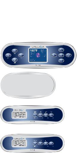
TP Panel Overview and User Guides
TP900 |
|
TP800 |
|
TP600 |
JETS AUX LIGHT HEAT |
TP400T |
|
TP400W |
|
System Models: BP2000 and other BP-Series Systems as required.
Panel Model: TP900 Series, TP800 Series
Software Version(s): Software versions vary and are constantly changing. See Tech Sheets for latest version and software compatibility.
User Guide 40985
System Models: BP500 and other BP-Series Systems as required.
Panel Model: TP600 Series, TP400 Series
Software Version(s): Software versions vary and are constantly changing. See Tech Sheets for latest version and software compatibility.
UÊ User Guide 40940
User Interface and Programming Reference – Standard Menus
UÊ User Guide 42185; Ref. Card 40947
User Interface and Programming Reference – Simplified Menus (See section TP400, TP600 Simplified vs. Standard Panel Operations for more information.)
NOTE: All TP panels work with all BP Spa Control Systems. They all have capabilities for navigation, setting functions and modes, such as time, temperature, filter cycles, preferences, sensor related messages, reminder messages, diagnostic messages, and utilities such as fault logs.
8 |
Manufactured under one or more of these patents. U.S. Patents: 5332944, 5361215, 5550753, 5559720, 5,883,459, 6253227, 6282370, 6590188, 6976052, 6965815, 7030343, 7,417, |
834 b2, |
5/02/13 |
Canadian Patent: 2342614, Australian patent: 2373248 other patents both foreign and domestic applied for and pending. All material copyright of Balboa Water Group. |
|

Product Identification
All TP Panels have “Molex” Type Connectors
On Every System, an Identification
Label Is Placed on Top of the Casing
Heater Element Specifications Are Shown
on the Heater Tube Label
On Every System, a Wiring Diagram
Is Placed Inside the Door
|
|
|
|
|
|
|
|
|
|
|
|
J43 TO J13 (BLOWER ON J14) |
|
|
|
|
|
|
|||||
|
|
|
|
|
|
|
|
|
|
|
|
IN SETUPS 3, 5, 9, 11, 12, 17, 18 |
|
|
|
|
|||||||
J25=HTR1 |
J9 |
|
|
|
|
J33 |
|
|
K9 |
J21 |
|
J32 |
|
|
|
|
J14 |
|
|
24082_E |
|||
J26=HTR2 |
|
|
|
|
|
|
|
CIRC PUMP |
|
J13 |
|
|
|
|
|
|
|||||||
J27=HTR3 |
|
|
|
K4 |
|
|
|
|
|
|
F2 10A 250VAC |
|
|
|
|
|
|
|
|
|
K6 |
||
J30=TEST |
|
J46 |
|
|
|
A/V HOT |
|
|
J20 |
|
|
|
|
|
J18 |
AUX** |
|
|
|||||
PUMP 1 |
|
|
|
|
|
|
|
OZONE |
|
|
|
|
|
|
|||||||||
J31=CE |
|
|
|
|
J38 |
|
J81 |
|
10A 250VAC |
|
|
|
|
|
|||||||||
HTR |
|
|
|
|
|
|
|
|
|
|
|
|
|||||||||||
SEL |
|
|
|
|
|
|
|
|
|
|
|
|
|||||||||||
|
|
|
|
|
|
|
|
K8 |
|
J50 |
|
|
|||||||||||
|
K2 |
J56 |
J57 |
J55 |
J59 |
|
|
|
J39 |
|
|
|
|
|
F7 |
|
|
|
|
|
|||
F6 30A |
|
|
|
J10 |
J43 |
|
|
|
|
|
J19 |
J34 |
J35 |
|
|
|
|||||||
|
|
|
|
|
|
|
|
K12 |
|
|
|
|
|
|
|
|
|||||||
|
J60 |
J41 |
|
F8 |
30A |
|
|
|
|
230V |
MAIN |
MAIN |
|
|
|||||||||
|
|
|
|
|
|
|
|
|
|
|
|
|
|
|
|||||||||
|
|
|
|
|
|
|
|
|
|
|
|
|
|
|
|
J24 |
|
|
|
|
|
|
J5 |
|
|
|
|
|
|
1 |
|
|
|
J109 |
|
|
|
|
|
115V |
115V |
J108 |
J107 |
J91 |
|
||
|
|
|
|
|
|
|
|
|
|
|
|
|
T1 |
|
|
AUX |
|||||||
TB1 |
|
J51 J52 J98 |
F3 0.125A SLO-BLOW |
|
|
|
|
|
|
|
|
|
|
|
|
|
|||||||
|
|
|
K1 |
|
|
|
|
|
|
|
|
|
|
J101 |
|
|
|||||||
|
1 |
|
|
|
|
|
|
|
|
|
|
|
|
|
|
|
|
|
J27 |
J23 |
|||
|
|
|
|
|
|
|
|
|
|
|
|
|
|
|
|
|
|
|
|
||||
|
|
|
|
J72 J42 J3 J61 |
2 |
|
|
K3 |
|
|
|
|
|
|
J22 |
|
|
|
SERIAL |
||||
|
|
|
|
|
|
|
|
|
|
|
|
J26 |
J30 |
|
|
|
|||||||
|
2 |
|
|
|
|
J49 |
J44 |
|
J48 |
|
|
|
|
|
|
||||||||
BLU |
|
|
J37 J4 J1 J47 |
|
|
|
|
|
|
|
|
|
|
|
|
|
|||||||
|
|
|
|
|
|
|
|
|
|
|
|
|
|
|
|
|
|
J8 |
|||||
BRN |
|
|
|
|
|
|
2 |
|
|
3 |
|
|
|
J25 |
J31 |
|
|
||||||
3 |
|
J36 J12 J88 J62 |
|
K5 |
|
|
|
|
J15 |
|
|
|
|
|
|
AUX |
|||||||
|
|
|
|
|
|
|
|
|
|
J7 |
|
J29 |
|
|
J40 |
||||||||
|
|
|
3 |
|
|
|
|
|
J6 |
LIGHT |
|
|
|
|
|||||||||
GRN |
4 |
|
|
|
|
|
|
|
K7 |
|
VAC |
|
|
REMOTE |
|||||||||
|
|
|
J53 |
J58 |
|
|
|
|
|
|
|
|
|
|
|
|
|
|
|
|
|||
J110 |
J45 J79 J54 J77 J75 J78 |
|
|
J111 |
|
|
|
|
|
|
|
|
|
F4 3A SLO-BLOW |
10 |
|
|
|
|
|
|||
|
|
|
|
|
|
|
|
|
|
|
|
|
|
|
J17 |
|
J16 |
||||||
|
|
|
|
|
|
|
|
|
|
GND |
|
|
|
|
|
|
|
||||||
|
4 |
|
|
|
|
J11 |
|
|
|
|
|
|
|
|
|
|
|
|
AUX |
|
|
|
|
|
|
|
|
|
|
|
|
|
|
|
|
|
|
ON S1 |
|
|
|
|
|
||||
|
|
|
|
|
|
|
|
|
|
|
|
|
|
|
|
J28 |
|
FRZ |
|
|
|
||
230V |
|
|
|
|
|
|
|
|
|
|
|
|
|
|
|
|
|
|
|
|
|
|
|
1þ |
|
|
|
|
|
|
|
|
|
|
|
|
|
|
|
|
|
|
|
|
|
|
|
1x32A |
|
|
|
|
|
|
|
|
|
|
|
|
|
|
|
|
|
|
|
|
|
|
|
SENSOR A |
|
|
|
|
|
|
|
SENSOR B |
|
|
|||
|
|
3.0 kW HEATER |
|
**J14 (AUX) IS: |
|
|
|
|
|
|
|
||
|
|
HEIZELEMENT |
|
|
|
|
|
|
|
2-SPEED PUMP 2 IN |
SETUPS 2-4, 7-10, 15, 16 |
||
|
|
RADIATEUR |
|
|||
|
|
|
1-SPEED PUMP 2 IN |
SETUPS 5, 6, 11–14 |
||
|
|
|
|
|||
|
|
|
|
1-SPEED BLOWER IN |
SETUPS 3, 5, 9, 11, 12, 17, 18 |
|
BP2100G1 – PN 56389-01
01-30-13
|
|
|
IR RECEIVER |
|
|
|
|
|
|
|
|
|
|
|
TP (MAIN) PANELS |
|||||||||
|
|
|
|
|
OR |
|
|
|
|
|
|
|
|
|
|
|
|
|
|
J34 OR J35 |
|
|||
|
|
|
RF RECEIVER |
|
|
|
|
|
|
|
|
|
|
|
|
|
|
|
|
|||||
|
|
|
|
|
|
|
|
|
|
|
|
|
|
|
|
|
|
|
|
J5 (A1-A4) |
||||
|
|
|
|
|
|
|
|
|
|
|
|
|
|
|
|
|
|
|
|
|||||
|
|
|
|
WIFI |
|
|
|
|
|
|
|
|
|
|
|
|
|
|
|
|||||
|
|
|
TRANSCEIVER |
|
|
|
|
|
|
|
|
|
|
|
|
AUX |
OR |
|
||||||
|
|
|
J34 OR J35 |
|
|
|
|
|
|
|
|
|
|
|
|
|
J8 (A5-A8) |
|||||||
|
|
|
|
|
|
|
|
|
|
|
|
|
|
|
|
|
|
|
|
|
|
|||
|
|
|
|
|
|
|
|
|
|
|
|
|
|
|
|
|
|
|
|
|
|
|
|
|
|
|
LOCATION |
DEVICE |
|
VOLTS |
|
AMPS |
FROM |
TO |
FROM |
|
|
TO |
|||||||||||
|
|
J1 ON RT |
2 SPD* |
|
230V |
|
12A |
W1 ON |
GROUP 2 |
J6 ON |
|
|
GROUP 3 |
|||||||||||
|
|
EXPANDER |
PUMP 3 |
|
|
|
|
MAX |
EXPANDER |
J1 |
EXPANDER |
|
J53 |
|||||||||||
|
|
|
|
|
|
|
|
|
|
|
|
|
|
|
|
|
|
|
|
NETZSTROMVERSORGUNG |
|
|||
|
|
|
EXPANDER |
|
|
|
|
RIGHT |
|
|
|
|
|
|
2-GESCHW.-PUMPE 3* |
|
||||||||
|
|
|
|
X-P332 |
|
|
|
|
EXPANDER |
|
|
J7 |
|
|||||||||||
|
|
|
|
|
|
|
|
|
|
ALIMENTATION POMPE 3 |
||||||||||||||
|
|
|
|
|
|
|
|
|
|
|
BOARD |
|
|
|
|
|
|
|||||||
|
|
W1 |
EXPANDER |
|
|
|
|
|
|
|
|
|
|
|
|
|
|
A 2 VITESSES* |
|
|
|
|||
|
|
|
|
|
|
|
|
|
|
|
|
|
J6 |
|
|
|
|
|
|
|
|
|
|
|
|
|
|
J1 |
|
|
|
|
F1 30A |
|
|
|
|
|
|
|
|
|
|
|
|
|
|
|
|
|
|
|
|
|
|
|
|
|
|
|
|
|
|
|
|
|
|
|
|
|
|
|||
|
|
|
|
|
|
|
|
|
|
|
|
|
|
|
|
|
|
|
|
|
|
|
|
|
|
|
|
|
|
|
|
|
|
|
|
|
|
|
|
|
|
|
|
|
|
|
|
|
|
*EXPANDER BOARD IS:
2-SPEED PUMP 3 IN SETUPS 1, 7
1-SPEED PUMP 3 (ONLY) IN SETUPS 2, 6, 8, 13, 14
1-SPEED PUMP 3 AND 1-SPEED BLOWER (WITH SPLITTER & IN-LINE FUSE) IN SETUPS 15, 16
1-SPEED PUMP 2 AND 1-SPEED PUMP 3 IN SETUPS 5, 11, 12 2-SPEED PUMP 2 IN SETUPS 3, 9
1-SPEED PUMP 2 IN SETUP 17, 18 UNUSED IN SETUPS 4, 10
PART A
42217B |
Manufactured under one or more of these patents. U.S. Patents: 5332944, 5361215, 5550753, 5559720, 5,883,459, 6253227, 6282370, 6590188, 6976052, 6965815, 7030343, 7,417, |
834 b2, |
Canadian Patent: 2342614, Australian patent: 2373248 other patents both foreign and domestic applied for and pending. All material copyright of Balboa Water Group. |
9 |

230 Volt / 50 Hz Residential Wiring Schematic with 2 Pole RCD Breaker Box
230VAC House Breaker Box |
RCD Breaker Box |
12
VAC230 |
Wire”“Live |
Neutral |
+ Ground |
|
9 |
|
|
|
|
|
|
|
|
|
|
|
8 |
ON |
OFF |
OFF |
|
ON |
7 |
|
|
||||
ON |
OFF |
OFF |
|
ON |
6 |
|
|
|
|
|
|
ON |
OFF |
OFF |
|
ON |
|
ON |
OFF |
OFF |
|
ON |
|
|
|
ON |
|
|
|
|
|
|
|
|
11 |
|
|
OFF |
|
|
|
|
|
|
|
|
10 |
Outside Ground Rod
|
|
|
|
|
|
|
|
|
|
|
|
|
|
Correct |
|
|
|
|
|
|
|
||||
|
|
|
|
|
|
|
|
When Probes Are Placed Across |
|
|||
|
|
Voltage |
|
|
||||||||
|
|
|
|
|
|
|
|
|
|
|||
|
|
|
|
|
|
|
|
|
|
|
|
|
|
|
|
0v |
[1 - 3] |
[4 - 7] |
[5 - 9] |
[10 - 11] |
|
|
|||
|
|
|
|
|
|
|
|
|
|
|
|
|
207V - 253V |
[1 - 2] |
[2 - 3] |
[4 - 6] |
[5 - 8] [6 -7] [8 - 9] [10 - 12] [11 - 12] |
||||||||
10 |
Manufactured under one or more of these patents. U.S. Patents: 5332944, 5361215, 5550753, 5559720, 5,883,459, 6253227, 6282370, 6590188, 6976052, 6965815, 7030343, 7,417, |
834 b2, |
5/02/13 |
Canadian Patent: 2342614, Australian patent: 2373248 other patents both foreign and domestic applied for and pending. All material copyright of Balboa Water Group. |
|
Spa System Box
J31=CE |
|
PUMP |
|
|
J |
HTR |
|
|
|
||
|
|
|
|
||
SEL |
|
|
|
|
|
|
|
|
|
|
|
F6 |
|
J56 |
J57 |
J55 |
J59 |
30A |
|
|
|
||
3 |
|
J60 |
J41 |
|
|
|
|
|
|
|
|
|
TB1 |
|
J51 |
J52 |
|
|
|
1 |
|
|
|
5 |
|
2 |
|
J72 |
J42 |
|
|
J37 |
|
||
|
|
|
|
||
4 |
|
3 |
|
J4 |
|
|
|
J36 |
J12 |
||
|
|
|
|
||
|
|
4 |
|
J53 |
|
|
0 |
5 9 4 7 5 8 |
|
J |
|
J25=HTR1 |
|
|
J9 |
|
|
|
|
|
|
J33 |
|
|
|
|
|
|
J32 |
|
|
|
|
|
|
|
|||
J26=HTR2 |
|
|
J46 |
|
|
|
K9 |
|
|
PUMP |
|
J13 |
|
|
|
|
|
K6 |
|||||||||
J30=TEST |
|
|
|
|
|
|
|
|
|
|
|
|
|
|
|
|
|
|
|
|
|
||||||
J27=HTR3 |
|
|
|
|
|
|
|
K4 |
|
|
HOTA/V |
|
|
|
250VAC10AF2 |
|
|
|
|
|
|
|
|
|
|
||
|
K2 |
PUMP1 |
|
|
|
|
|
|
|
J39 |
J81 |
|
J20 |
|
OZONE |
250VAC10A |
K8 |
|
J18 |
AUX** |
J50 |
||||||
J31=CE |
|
|
|
|
|
|
J38 |
|
|
|
|
||||||||||||||||
HTR |
|
|
|
|
|
|
|
|
|
|
|
|
|
|
|
|
CIRC |
|
|
|
|
|
|
|
|
|
|
SEL |
|
|
|
|
|
|
|
|
|
|
|
|
|
|
|
|
|
|
|
|
|
|
|
|
|
|
|
F6 30A |
|
|
|
J56 |
J57 |
J55 |
J59 |
|
|
J10 |
J43 |
|
|
|
|
|
|
F7 |
J19 |
J34 |
J35 |
|
|||||
|
|
|
|
|
|
|
|
|
|
|
|
K12 |
|
|
|
|
|
|
|||||||||
|
|
J60 J41 |
|
|
F8 30A |
|
|
|
|
230V |
MAIN |
MAIN |
|
||||||||||||||
|
|
|
|
|
|
|
|
|
|
|
|
|
|
|
|
|
|||||||||||
|
|
|
|
|
|
|
|
|
|
|
|
|
|
|
|
|
J24 |
|
|
|
|
|
J5 |
||||
|
|
|
|
|
|
|
|
|
|
1 |
|
|
|
J109 |
|
|
|
|
|
|
115V |
115V |
J108 J107 |
J91 |
|||
|
|
|
|
|
|
|
|
|
|
|
|
|
|
|
|
|
|
T1 |
|
AUX |
|||||||
TB1 |
|
|
|
|
|
|
J51 |
J52 |
J98 |
F3 0.3A SLO-BLOW |
|
|
|
|
|
|
|
|
|
|
|
|
|||||
|
|
1 |
|
|
|
|
|
|
|
|
|
|
K1 |
|
|
|
|
|
|
|
|
|
|
|
J101 |
J27 J23 |
|
|
|
|
|
|
|
|
|
J72 |
J42 |
|
J61 |
|
|
|
|
K3 |
|
|
|
|
|
|
J22 |
|
|
|
SERIAL |
|
|
|
|
|
|
|
|
J3 |
2 |
|
|
|
|
|
|
|
|
|
J26 |
J30 |
|
|
|||||
|
|
2 |
|
|
|
|
|
|
|
|
J49 |
J44 |
J48 |
|
|
|
|
|
|||||||||
|
|
|
|
|
|
|
J37 |
J4 |
J1 |
J47 |
|
|
|
|
|
|
|
|
|
|
|
|
|||||
|
|
|
|
|
|
|
|
|
|
|
|
2 |
|
|
3 |
|
|
|
J25 |
J31 |
|
J8 |
|||||
|
|
3 |
|
|
|
|
|
J36 |
J12 |
J88 |
J62 |
|
K5 |
|
|
|
|
|
J15 |
|
|
|
|
|
AUX |
||
|
|
|
|
|
|
|
|
3 |
|
|
|
|
|
J6 |
|
K7 |
J7 |
|
VAC |
|
J40 |
||||||
|
|
|
|
|
|
|
|
|
|
|
|
|
|
LIGHT |
|
|
|||||||||||
|
|
|
|
|
|
|
|
|
|
|
|
|
|
|
|
|
|
|
|
|
|
|
|
J29 |
|
||
|
|
4 |
|
|
|
|
|
J53 |
J58 |
|
|
|
|
|
|
|
|
|
|
|
|
|
|
|
REMOTE |
||
J110 |
J45 |
J79 |
J54 |
J77 |
J75 |
J78 |
|
J111 |
|
|
|
|
|
|
|
|
F4 3A SLO-BLOW |
10 |
|
|
J17 |
J16 |
|||||
|
|
|
|
|
|
|
|
|
|
|
|
|
|
||||||||||||||
|
|
|
4 |
|
|
|
|
|
J11 |
|
|
|
|
|
|
|
GND |
|
|
|
|
|
AUX |
|
|
||
|
|
|
|
|
|
|
|
|
|
|
|
|
|
|
|
|
|
|
|
|
ON S1 |
J28 |
|
FRZ |
|
|
|
1
2
3
K4 4
J32 J33
Test for Voltages by placing probes on these locations
1
2
42217B |
Manufactured under one or more of these patents. U.S. Patents: 5332944, 5361215, 5550753, 5559720, 5,883,459, 6253227, 6282370, 6590188, 6976052, 6965815, 7030343, 7,417, |
834 b2, |
Canadian Patent: 2342614, Australian patent: 2373248 other patents both foreign and domestic applied for and pending. All material copyright of Balboa Water Group. |
11 |
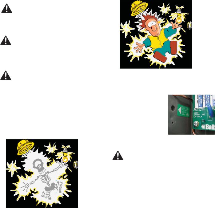
General Troubleshooting & Servicing of Spa's Electrical Equipment
HIGH VOLTAGE CAN SERIOUSLY INJURE OR KILL!
ONLY EXPERIENCED TECHNICIANS SHOULD SERVICE THIS EQUIPMENT.
DO NOT REMOVE THE PROTECTIVE COVERS FROM ANY ELECTRICAL ENCLOSURE, OR ATTEMPT TO SERVICE ANY RELATED ELECTRICAL DEVICE, UNLESS YOU ARE A QUALIFIED ELECTRICIAN OR SERVICE PROFESSIONAL.
DANGER
Risk of electric shock. Before working with any electrical connections, make certain that the Main Power breaker from the house breaker box has been turned off.
WARNING
ALL ELECTRICAL WORK MUST BE PERFORMED BY A QUALIFIED ELECTRICIAN AND MUST CONFORM TO ALL
LOCAL CODES.
IMPORTANT
DUE TO THE DANGER OF SEVERE ELECTRICAL SHOCK, LOCATE ALL POWER DISCONNECTS BEFORE SERVICING A SPA. PRECAUTIONS MUST BE TAKEN WHENEVER WORKING WITH BREAKER BOXES, G.F.C.I.’S, OR SERVICE
DISCONNECTS.
Always refer to the wiring diagram that is included with each system on the inside of the system box cover. Use this diagram for voltage measurement points, and for proper reconnection of wires.
A terminal marked “GROUND” is provided within the System Control Center enclosure. To reduce the risk of electrical shock, connect this terminal to the grounding
terminal of the electric supply panel with a continuous green insulated copper wire equivalent in size to the circuit conductors supplying this
equipment, but no smaller than #12 AWG.
Ground in System Enclosure
SAFETY TIPS
UÊ Keep children and pets away.
UÊ Be aware of your surroundings. Standing in water while repairing a spa puts you at serious risk.
UÊ Avoid working in cramped or crowded conditions.
UÊ Consider placing a padlock on the service panel to lock out anyone who might power up the system.
12 |
Manufactured under one or more of these patents. U.S. Patents: 5332944, 5361215, 5550753, 5559720, 5,883,459, 6253227, 6282370, 6590188, 6976052, 6965815, 7030343, 7,417, |
834 b2, |
5/02/13 |
Canadian Patent: 2342614, Australian patent: 2373248 other patents both foreign and domestic applied for and pending. All material copyright of Balboa Water Group. |
|
Basic Control System Troubleshooting
Note: Local codes and laws vary. Use information below as a guide.
LOW VOLTAGE
At Balboa, it’s been our experience that the majority of the problems associated with electronic control systems are due to low voltage.
BROWN OUTS
“Brown outs” can have an effect on the spa’s operation in a variety of ways. The control panel may go blank, have scrambled messages on the LCD, or only a few features will function.
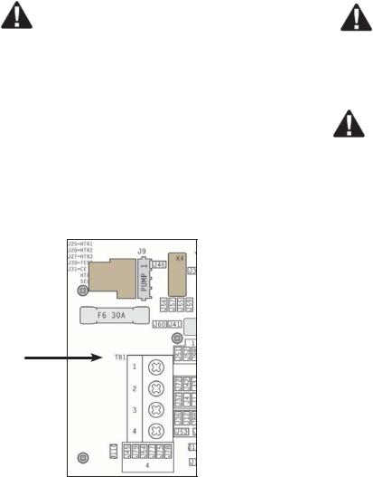
If the system is getting the proper voltage at TB1, but still doesn’t operate, then test for a blown power input fuse.
J25=HTR1 |
|
|
|
J9 |
|
|
|
|
|
|
|
J26=HTR2 |
|
|
|
|
|
|
|
K4 |
|||
J27=HTR3 |
|
|
|
|
|
J46 |
|
||||
J30=TEST |
|
|
|
|
1 |
|
|
J |
|||
J31=CE |
|
|
|
|
PUMP |
|
|
|
|
|
|
HTR |
|
|
|
|
|
|
|
|
|
|
|
SEL |
|
|
|
|
|
|
|
|
|
|
|
|
|
|
|
|
|
|
|
|
|
|
|
|
|
K2 |
|
|
|
J56 |
J57 |
J55 |
J59 |
||
F6 |
30A |
|
|
|
|
||||||
|
|
|
J60 J41 |
|
|||||||
F6 Fuse |
|
|
|
|
|
|
|||||
|
|
|
|
|
|
|
|
|
|
|
|
|
TB1 |
|
|
|
|
|
|
|
J51 |
J52 |
|
TB1 |
|
|
1 |
|
|
|
|
|
|
|
|
|
|
|
|
|
|
|
|
|
J72 |
J42 |
|
|
|
|
2 |
|
|
|
|
|
|
||
BLU |
|
|
|
|
|
|
|
|
J37 |
|
|
|
|
|
|
|
|
|
|
|
J4 |
||
|
|
|
3 |
|
|
|
|
|
|
||
BRN |
|
|
|
|
|
|
|
|
J36 |
J12 |
|
|
|
|
|
|
|
|
|
|
|||
|
|
|
|
|
|
|
|
|
|
|
|
GRN |
|
|
4 |
|
|
|
|
|
|
J53 |
|
J110 |
J45 |
J79 |
J54 |
J77 |
J75 |
J78 |
|
|
|||
|
|
J |
|||||||||
|
|
|
|
|
|
|
|
|
|
|
|
|
|
|
|
|
4 |
|
|
|
|
J |
|
|
|
|
|
|
|
|
|
|
|
||
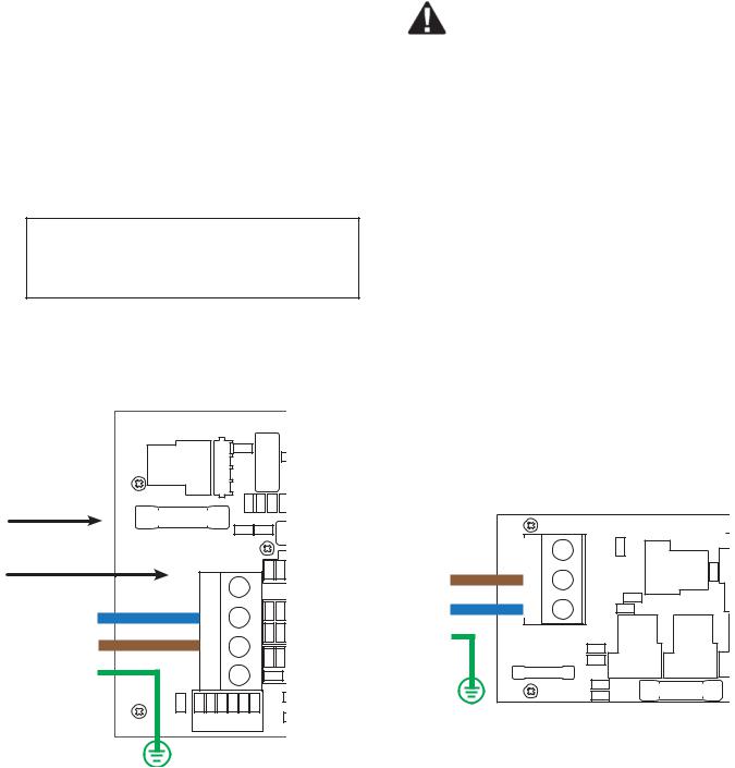
Terminal Block & F6
Fuse on a BP2100 Board
CHECKING THE SYSTEM POWER INPUT FUSE
WARNING
These procedures are performed while the system is powered up and running under peak loads. Be careful.
Systems that use 230V peripheral devices (below):
UÊ Measure between the brown TB1 terminal and F6 power input fuse at F6. You should see 230 volts.
UÊ If you determine that there is no voltage at this location, then the system power input fuse needs to be replaced. Only use a fuse of the same type and amp rating when you replace any of these fuse.
UÊ NOTE FOR ALL SYSTEMS In each situation, the most likely reason for the system power input fuse to blow is a pump problem. (cont. next page)
Once the power input fuse has been changed
UÊ Check the voltage between the black and red wires again. Acceptable voltage range is between 216V and 264V.
|
22117_B |
GND |
ADDED JUMPER FOR |
|
|
|
CE INSTALLATIONS |
||
|
N/A N |
J24 |
K5 |
K6 |
|
|
|
|
|
|
L1 |
|
|
J15 |
BRN |
|
|
|
|
|
J45 |
|
|
|
|
|
HTR A |
|
|
BLU |
L2N |
J49 |
|
|
|
|
|
|
|
GRN |
HTR B |
J44 |
|
|
|
F6 |
J48 |
|
|
|
T 150mA 250V |
|
K3 |
K1 |
|
UNFUSED |
J1 |
F5 T 30A |
|
|
J2 |
|
||
Terminal Block & F6 Fuse on a
BP600 Power Board, 230V Setup
42217B |
Manufactured under one or more of these patents. U.S. Patents: 5332944, 5361215, 5550753, 5559720, 5,883,459, 6253227, 6282370, 6590188, 6976052, 6965815, 7030343, 7,417, |
834 b2, |
Canadian Patent: 2342614, Australian patent: 2373248 other patents both foreign and domestic applied for and pending. All material copyright of Balboa Water Group. |
13 |
Basic Control System Troubleshooting (cont.)
THESE READINGS SHOULD BE TAKEN UNDER PEAK LOAD CONDITIONS.
IMPORTANT
If the voltage is not in the acceptable range, call an electrician or the local electric company to diagnose the problem.
TO DETERMINE THE CAUSE OF A BLOWN POWER INPUT FUSE
Perform the following sequence of tests.
Test the System
UÊ Turn the power off.
UÊ Be sure to replace the system power input fuse with the same type.
UÊ Unplug the blower and all pumps.
UÊ Restore the power and verify system operation.
UÊ If the fuse blows, then re-check the internal system wires and connector for burns, cracks or cuts in insulation.
UÊ If the fuse does not blow, turn the power off and plug in the pump.
NOTE: Be sure to test each device individually.
Test the Pump
UÊ Restore the power and activate the pump. UÊ If the fuse blows, there is a pump problem. UÊ If the fuse does not blow, turn off the power.
Test the Blower
UÊ Plug in the blower.
UÊ Power up the system and activate the blower.
UÊ If the fuse blows, then there is a blower problem.
UÊ If the fuse does not blow, the combined pump and blower amperage may be excessive. To verify this, first check with your spa manufacturer for amperage draw limits on each device.
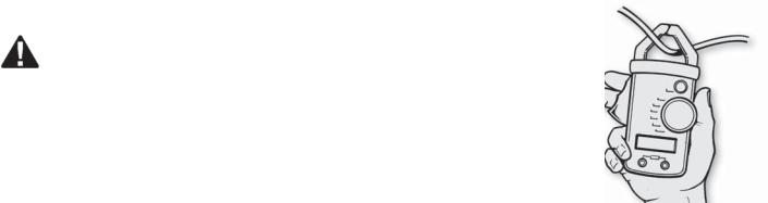
UÊ Since the blower should now be running, you can check the amperage draw with an ammeter by measuring around the black blower wire and compare with manufacturer’s specifications.
TEST THE AMPERAGE DRAW
Turn off the power, disconnect the blower, make sure the pump is plugged in, and restore power.
UÊ Start the pump and switch to high speed (if available), this should draw the most current.
UÊ Make sure all jets and valves are open.
UÊ Check the amperage at the red pump wire. Compare your
reading with manufacturer specifications. (If the other plugin devices exist, they should be tested in the same way.)
UÊ If the amperage draw for each device is within manufacturer’s specifications, the problem could be a nuisance spike in the pump, or water in the blower.
NOTE: These slow-blow fuses are not always discolored when blown. Always test continuity of a fuse with an ohmmeter.
NOTE: Miswiring of the spa is the most common reason for this fuse to blow. However, a lightning strike in the area is a possible, though less likely, cause of the failure.
14 |
Manufactured under one or more of these patents. U.S. Patents: 5332944, 5361215, 5550753, 5559720, 5,883,459, 6253227, 6282370, 6590188, 6976052, 6965815, 7030343, 7,417, |
834 b2, |
5/02/13 |
Canadian Patent: 2342614, Australian patent: 2373248 other patents both foreign and domestic applied for and pending. All material copyright of Balboa Water Group. |
|

Testing a System with Power
See manufacturer’s owners manual or reference card for general information on operating the spa, including programming filters and other settings that are changed from the topside control panel.
HEATER START UP INFORMATION
On M-7 systems, the heater goes through a testing phase every time it starts up to assure that there is adequate water flow. This provides sophisticated dry fire and low flow protection. It can be confusing if you don't know what to expect. Step by step, here is what happens. (Note that the timing/temperature details may be slightly different on some older M7 systems.)
UÊ Prior to heating, the pump is run for at least two minutes, and then the temperature difference between the sensors is assessed. It must be 2°F/1.0°C or less for heating to proceed, otherwise an error is issued.
UÊ The heater turns on for 6.5 to 18 seconds (depending on heater voltage and wattage). At this point, the heat indicator on the panel is "solid". During this time the panel is not immediately responsive.
UÊ The heater turns off for 90 seconds, making sure that the water flow keeps the temperature rise small and short. (Abnormal water flows, or lack of water, will produce a large and/or long temperature rise, and the system faults in that situation.) At this point, the heat indicator on the panel may appear to "shimmer" or "dim" (on some panels this may be less obvious from certain angles and more obvious from other angles, or in different lighting).
UÊ If the dry fire test has passed, heating turns back on to heat the spa. The heat indicator on the panel returns to "solid".
UÊ During spa heating, a difference between the sensors of 2°F/1.0°C, or perhaps 3°F/1.5°C (at least with 4-6kW
240V heaters), is considered normal. A significantly higher difference, however, is usually indicative of a flow problem, and will cause a fault which disables the heating for at least a minute (and then restarts the whole above process).
PRELIMINARY PANEL CHECK
UÊ If the problem is not obvious, look on the topside control panel for diagnostic messages.
UÊ If no messages are seen, run through all spa functions and note any inconsistent operation.
UÊ Most error messages are stored in the fault log. To view the fault log, the spa must be in test mode and the spa light must be turned on.
Once you have determined that proper voltage is running through the circuit board and transformer, continue to the topside control panel. A panel that is not functioning properly may include the following symptoms: low voltage such as missing or scrambled
segments, missing icons on the LCD, non-functional LED’s, or nonfunctional buttons. If any of these symptoms are present, perform the following:
UÊ Turn the power off and unplug the panel from the circuit board.
UÊ Then, plug in your test panel and restore power. If everything functions normally, replace the topside panel.
UÊ Disconnect ozone generator (if applicable).
UÊ If you still see symptoms of low voltage, such as a sluggish, blank or partially blank panel, or if the display or the LED’s do not function at all, turn the power off; unplug the ozone generator (if equipped); then restore power to the system. If the problem persists, turn off the power and replace the circuit board.
FLASHING HEAT LED ON TP600 ("HEAT WAITING")
When there is a call for heat, the system will start the heater for a few seconds and the Heat LED will light. After a few seconds of heat, the heater will shut off for 90 seconds and the sys-
tem will look at the sensors to be sure they are within the M7 parameters for flow and a safe environment to run the heater. During this 90 second wait time, the Heat LED will flash quickly, or "shimmer", until the heater comes on again to heat. There is no voltage to the heater during this cycle. This is normal for M7. Once the heater comes back on, the LED will be on without shimmering. On the TP800 and TP900 panels, the screen will display "Heat Waiting".
JETS AUX |
LIGHT HEAT |
Heat LED in Heat Waiting Mode, TP600
42217B |
Manufactured under one or more of these patents. U.S. Patents: 5332944, 5361215, 5550753, 5559720, 5,883,459, 6253227, 6282370, 6590188, 6976052, 6965815, 7030343, 7,417, |
834 b2, |
Canadian Patent: 2342614, Australian patent: 2373248 other patents both foreign and domestic applied for and pending. All material copyright of Balboa Water Group. |
15 |
Testing a System with Power (cont.)
MOST PROBABLE OVERHEATING CAUSES, INSPECT THESE FIRST
UÊ Check slice or ball valves. Make sure that they are open. UÊ Make sure the correct pump is installed.
UÊ Clean the filter/skimmer if there is any blockage. UÊ Check heater element alignment.
UÊ Check for debris on the heater element.
UÊ In extremely hot weather, check for proper cabinet ventilation.
UÊ Make sure the temperature sensor is fully inserted into the sensor fitting on the heater.
UÊ Check for excessive filter duration. UÊ Check the water level.
UÊ Check the water temperature with an accurate temperature thermometer. Remove the spa cover and allow the water to cool to below 108° F. Adding cool water may be necessary.
Touch any button to reset the system. If the water is still hotter than the set temperature, press the blower button (if applicable) to cool the spa.
UÊ If the Problem Recurs, test the Sensor Set.
NOTE:
A common programming mistake is overlapping filter times that may cause the spa to filter continuously.
If alternating with temperature, it may just be a temporary condition. If flashing by itself, spa is shut down.
If the panel also displays “Service Req” spa is shut down. If the spa shuts down due to this error, one (or both) of the
sensors are probably reading several degrees off. If the problem recurs, test the sensor set.
FREEZE CONDITION
When either sensor reads below 40°F (4°C), the system provides freeze protection. It automatically activates the pump (and the heater if necessary) to circulate the water and warm the plumbing. The equipment stays on until the sensors detect that the spa temperature has risen to within 15°F of the set temperature. The other pumps and the blower will purge for 30 seconds to 2 minutes at the end of the freeze condition. If pump 1 was turned on due to this reason alone, this message will appear for up to two minutes right after very cold water is detected.
NOTE: Internal freeze protection only functions when there is proper power running to the spa, and the control system is operational. Using an optional freeze sensor may be necessary in extreme climates to prevent plumbing damage, but will only
work properly if placed inside the spa skirt in the coldest area. All spa models are different in shape and size and have different thermal characteristics; therefore, Balboa Water Group cannot be held responsible for freeze damage to the spa’s plumbing. Testing is the responsibility of the spa manufacturer and must be done to determine the best location for the freeze sensor.
SOME TROUBLESHOOTING SCENARIOS
You find out the system is in “OHH”. This alone doesn't explain a lot. What led up to the “OHH” is much more important. If it's a Prestige, review the fault log carefully. Otherwise, see if the user has any additional information (for example, how long before
the “OHH” was the spa panel last checked, and how hot was the water then). If the spa has cooled, see whether the problem can happen again, this time watching carefully to see if there are additional clues leading to the “OHH” (for example, other messages that appear shortly before the “OHH” happens).
You find out the system keeps showing “HFL,” or is now in “LF,” or is shut down due to a "dry" fault. Put the spa in test mode with the light on, so that you see the two sensor temperatures. Are they normal (within 1°F/0.5°C) when not heating? How far apart are they when heating? “HFL” happens when they are 6°F/3°C apart (4°F/2°C on 120V and other low-heater-wattage systems), see how quickly that happens after heating starts. If it's getting close to that right away, it's probably a consistent flow problem, but if it's nowhere close to the “HFL”-causing temperature difference, the flow problem may be intermittent or only occur in certain specific situations.
TEST MODE
Test modes vary for different systems and configurations. Please refer to the specific Tech Sheet applicable.
MESSAGE CODES
Refer to Tech Sheets for each system code. Or, a general set of codes for BP systems is found under the sectionTP400, TP600 Message Codes in this manual. Message codes are the same for all TP panels.
16 |
Manufactured under one or more of these patents. U.S. Patents: 5332944, 5361215, 5550753, 5559720, 5,883,459, 6253227, 6282370, 6590188, 6976052, 6965815, 7030343, 7,417, |
834 b2, |
5/02/13 |
Canadian Patent: 2342614, Australian patent: 2373248 other patents both foreign and domestic applied for and pending. All material copyright of Balboa Water Group. |
|
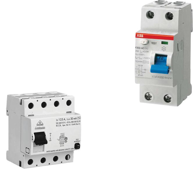
230 Volt 50 Hz - Residual Current Devices (RCD’s)
A residual current device (RCD,) is the generic term for a device that monitors the current in the line conductor and the neutral conductor of a circuit in an earthed system.
Two Pole RCD
In a circuit that’s operating properly, the vector sum of the live and neutral current values added together will be zero. Current flowing to earth, due to a line earth fault, will return via the earth conductor, and regardless of load conditions, will be registered as a fault. This current flow will give rise to a residual current that will be detected by the device. If the residual current exceeds the rated sensitivity of the RCD, it will automatically activate a tripping of the faulty circuit.
Typical specifications are as follows:
Residual Current Devices ( RCD’s ) range Sensitivity - from 10 to 500mA
Voltage - 2 poles : 230V; 3/4 poles: 230/400V Connection capacity
- 25A: 6/10 mm² (flexible/ rigid cable) - 40,60A: 16/25 mm²
- 80,100A: 35/50 mm²
Four Pole RCD
42217B |
Manufactured under one or more of these patents. U.S. Patents: 5332944, 5361215, 5550753, 5559720, 5,883,459, 6253227, 6282370, 6590188, 6976052, 6965815, 7030343, 7,417, |
834 b2, |
Canadian Patent: 2342614, Australian patent: 2373248 other patents both foreign and domestic applied for and pending. All material copyright of Balboa Water Group. |
17 |
Wiring Checks
WIRING CHECK PRECAUTIONS
UÊ When working in a system box always be aware that it may contain high voltage.
UÊ Always keep your fingers and hand tools away from any wiring or circuit board when the power is on. Touching anything in these areas can result in serious injury.
UÊ All service calls, no matter how minor, should include a complete wiring check, beginning with the house breaker.
TB1
CHECK FOR LOOSE CONNECTIONS OR
DAMAGED WIRES
UÊ Make sure the power is off before you touch any wiring. UÊ Once the power is off, carefully examine all wires for
cuts or defects.
SYSTEM BOX WIRE GAUGE CHECK
UÊ When inspecting the wiring for any control system, note that connections for the incoming wires are clearly labeled at the main terminal block.
UÊ 30A service – minimum ten gauge copper wire. UÊ These wires must connect the house breaker box,
through the local disconnect, to the main terminal block. The wiring diagram inside the system box shows the main terminal block as TB1.
IMPORTANT -- USE OF NON-COPPER WIRE
Using non-copper wire can be dangerous, and also can be the cause of a spa’s malfunction. If non-copper wire
is used at any point, we do not recommend servicing the spa until an electrician replaces it with the proper gauge copper wire.
Total Ampere Rating of |
Minimum wire size |
Ampere Rating of |
Power System |
Use Copper ONLY, |
RCD Circuit-breaker |
|
with 90 o C insulation |
|
0 A to 16 A |
#12 AWG |
20 |
|
|
|
16 A to 20 A |
#10 AWG |
25 |
|
|
|
20 A to 24 A |
#10 AWG |
30 |
24 A to 28 A |
#8 AWG |
35 |
|
|
|
28 A to 32 A |
#8 AWG |
40 |
|
|
|
18 |
Manufactured under one or more of these patents. U.S. Patents: 5332944, 5361215, 5550753, 5559720, 5,883,459, 6253227, 6282370, 6590188, 6976052, 6965815, 7030343, 7,417, |
834 b2, |
5/02/13 |
Canadian Patent: 2342614, Australian patent: 2373248 other patents both foreign and domestic applied for and pending. All material copyright of Balboa Water Group. |
|
Wiring Check for RCD and Service Disconnect
 IMPORTANT!
Remember, high voltage is still accessible in the house breaker box even though you have turned off the spa breaker.
Keep in mind that a majority of R.C.D. tripping problems can be attributed to incorrect wiring. R.C.D. troubleshooting usually finds the problem.
RCD LINE-IN WIRING CHECK
UÊ V>ÌiÊÌ iÊ«À «iÀÊVÀVÕÌÊLÀi> iÀÊ> `ÊÌÕÀ Ê ÌÊ vv°
UÊ ,i ÛiÊÌ iÊV ÛiÀÊvÀ ÊÌ iÊ ÕÃiÊLÀi> iÀÊL Ý°Ê iV the main service amperage rating to the breaker box.
UÊ À ÊÌ iÊVÀVÕÌÊLÀi> iÀ]Ê V>ÌiÊÌ iÊLÀ Ü Ê >`ÊÜÀiÊ> `ÊÌ iÊ blue neutral wire.
UÊ À ÊÌ iÊ,° ° °Ê iÕÌÀ> ÊL>À]Ê V>ÌiÊÌ iÊL ÕiÊ >`Ê iÕÌÀ> ]Ê> `Ê the green ground wire.
UÊ iÊÃÕÀiÊÌ iÀiÊ>ÀiÊ Ê Ì iÀÊ>«« > ViÃÊ ÊÌ iÊë>Ê circuit. If there are, service must be re-wired to supply the spa only.
UÊ > iÊÃÕÀiÊ> ÊÌ ÀiiÊÜÀiÃÊiÝ ÌÊÌ iÊ ÕÃiÊLÀi> iÀÊL ÝÊÛ >Ê conduit, routed to the R.C.D. breaker box. The brown should be connected to the R.C.D. line-in. The blue load neutral connects to the neutral in.
RCD LINE-OUT WIRING CHECK FOR 230 V DEDICATED SYSTEM
The brown wire should connect to load out, the blue wire from neutral out. All wires will exit the box via conduit routed to the spa control system.
Once you have found all wiring correctly installed, begin to check for proper voltage. If Correct Wiring is Verified, check to see if the proper RCD is installed.
UÊ Check the label in the system box near TB1 to determine the maximum amperage draw for the system.
UÊ Be sure the R.C.D. is rated for more amperage than the system will draw.
UÊ For a 230 V dedicated system, a 2-pole or 4-pole R.C.D. with no load neutral is acceptable.
UÊ For a detailed wiring checklist, please review the previous segment of this manual on proper R.C.D. wiring or the R.C.D. manufacturer’s instructions.
UÊ If the wiring is correct and the R.C.D. will not reset, then unplug the pump and try to reset the R.C.D.
UÊ If the R.C.D. trips again, then unplug the blower and push the reset button. If the R.C.D. continues to trip, then do the same procedure for the ozone generator.
UÊ If the R.C.D. stops tripping after you unplugged one of the spa’s components, turn off the power to the spa then plug in each component except the one that tripped the R.C.D.
UÊ Power up the system. If the R.C.D. no longer trips, then you have correctly identified the problem.
UÊ Repair or replace the component as instructed by the spa manufacturer.
UÊ If you have unplugged all of the spa’s components and the R.C.D. still doesn’t reset, then the problem is most likely a ground fault in the heater.
UÊ Disconnect the heater, and test.
42217B |
Manufactured under one or more of these patents. U.S. Patents: 5332944, 5361215, 5550753, 5559720, 5,883,459, 6253227, 6282370, 6590188, 6976052, 6965815, 7030343, 7,417, |
834 b2, |
Canadian Patent: 2342614, Australian patent: 2373248 other patents both foreign and domestic applied for and pending. All material copyright of Balboa Water Group. |
19 |

20 |
|
Patent: Canadian |
one under Manufactured |
All .pending and for applied domestic and foreign both patents other 2373248 patent: Australian 2342614, |
6282370, 6253227, 5,883,459, 5559720, 5550753, 5361215, 5332944, Patents: .S.U .patents these of more or |
.Group Water Balboa of copyright material |
7,417, 7030343, 6965815, 6976052, 6590188, |
|
b2, 834 |
Troubleshooting Pumps, Problem & Cause
Problem |
Pump motor |
Pump will not |
Pump not |
Jets not fully |
Low water |
Water |
No air |
Contact qualified |
Pump |
Cause |
does not |
turn off |
pumping |
functioning |
pressure / |
leakage |
mixed |
electrician for |
hums, |
|
start |
|
properly |
|
flow |
f/ unions |
into water |
service |
noisy |
GFCI / Fuse |
X |
|
|
|
|
|
|
X |
|
No incoming power |
|
|
|
|
|
|
|
||
|
|
|
|
|
|
|
|
|
|
|
|
|
|
|
|
|
|
|
|
Thermal overload tripped |
X |
|
|
|
|
|
|
X |
|
|
|
|
|
|
|
|
|
|
|
Air button, or switch on pump defec- |
X |
X |
|
|
|
|
|
X |
|
tive |
|
|
|
|
|
|
|||
|
|
|
|
|
|
|
|
|
|
|
|
|
|
|
|
|
|
|
|
Air tube blocked, kinked, or dis- |
X |
X |
|
|
|
|
|
X |
|
lodged |
|
|
|
|
|
|
|||
|
|
|
|
|
|
|
|
|
|
|
|
|
|
|
|
|
|
|
|
Jets are closed |
|
|
X |
X |
X |
|
|
X |
|
|
|
|
|
|
|
|
|
|
|
Leaks / loss of prime |
|
|
X |
|
|
|
|
X |
|
|
|
|
|
|
|
|
|
|
|
Low voltage; is there proper |
|
|
X |
|
|
|
|
X |
X |
voltage? |
|
|
|
|
|
|
|||
|
|
|
|
|
|
|
|
|
|
|
|
|
|
|
|
|
|
|
|
Motor burnt, flooded by water |
X |
|
|
|
|
|
|
X |
|
|
|
|
|
|
|
|
|
|
|
Open air control valves |
|
|
|
|
|
|
X |
|
|
|
|
|
|
|
|
|
|
|
|
O-ring over / under tightened, |
|
|
|
|
|
X |
|
X |
|
pinched, improperly seated |
|
|
|
|
|
|
|
||
|
|
|
|
|
|
|
|
|
|
|
|
|
|
|
|
|
|
|
|
Pipe inlet higher than water line |
|
|
X |
|
X |
|
|
X |
|
|
|
|
|
|
|
|
|
|
|
Pump jammed with debris |
X |
|
X |
|
X |
|
|
X |
X |
|
|
|
|
|
|
|
|
|
|
Pump not installed at correct level |
|
|
X |
X |
|
|
|
X |
|
|
|
|
|
|
|
|
|
|
|
Suction cover/guard, impeller, or |
|
|
X |
X |
X |
|
|
X |
X |
filter may be clogged |
|
|
|
|
|||||
|
|
|
|
|
|
|
|
|
|
|
|
|
|
|
|
|
|
|
|
Water level too low |
|
|
X |
X |
|
|
|
|
|
|
|
|
|
|
|
|
|
|
|
Bearings bad |
|
|
|
|
|
|
|
X |
X |
|
|
|
|
|
|
|
|
|
|
5/02/13
Acceptable Ranges for Testing Equipment
VOLTAGE CHECKLIST
All voltages specified as 120 V or 240 V, may show an acceptable variance of +/- 10%.
Voltage Ranges |
|
|
|
Wire Combo |
Voltage |
+/- 10% Range |
|
Black & Red |
240 V |
216 V - 264 V |
|
Black & White |
120 V |
108 V - 132 V |
|
Red & White |
120 V |
108 V - 132 V |
|
Black& Green |
120 V |
108 V - 132 V |
|
Red & Green |
120 V |
108 V - 132 V |
|
Green & White |
0 V |
* |
* |
* Depending on variables such as length of run, type of wire and temperature, small voltage readings may sometimes occur between ground and neutral.
MOTOR AMPERAGE GUIDELINES
The following ranges represent general parameters for many different motors and applications. Check the device label or with the spa manufacturer to get accurate amperage draws.
AMPERAGE DRAW RANGES
DEVICE |
120 V DRAW |
240 V DRAW |
Pump low |
2 A - 5 A |
2 A - 4 A |
Pump high |
10 A - 14 A |
8 A - 12 A |
Blower |
6 A - 8 A |
3 A - 4 A |
HEATER MATRIX
ACCEPTABLE HEATER AMPERAGE DRAW RANGES
Heater Type |
120V Amp Draw |
240V Amp Draw |
5.5 kW @ 240 V |
10.42 A - 12.74 A |
20.83 A - 25.48 A |
4 kW @ 240 V |
7.58 A - 9.26 A |
15.15 A -18.52 A |
1 kW @ 120 V |
7.58 A - 9.26 A |
- - - |
ACCEPTABLE HEATER OHM (Ω) RANGES
Heater Type |
Ohms (Ω) |
5.5 kW @ 240 V |
9.42 Ω-11.52 Ω |
4 kW @ 240 V |
12.96 Ω -15.84 Ω |
1 kW @ 120 V |
12.96 Ω- 15.84 Ω |
TEMPERATURE & HIGH-LIMIT SENSOR OHM TABLE
Temp. |
Ohms |
of Sensor |
(kΩ)** |
40° F |
76.686 kΩ |
45° F |
67.112 kΩ |
50° F |
58.858 kΩ |
60° F |
45.550 kΩ |
70° F |
35.533 kΩ |
80° F |
27.931 kΩ |
Temp. of |
Ohms |
Sensor |
(kΩ)** |
90° F |
22.117 kΩ |
100° F |
17.636 kΩ |
105° F |
15.788 kΩ |
110° F |
14.158 kΩ |
115° F |
12.716 kΩ |
120°F |
11.439 kΩ |
**Note: 1 kΩ= 1000 Ω:
kΩmay vary +/- 10% depending on the accuracy of the thermometer and meter used.
Heater Type |
Ohms |
120V Amp Draw |
120V Watts |
240V Amp Draw |
240V Watts |
230V Amp Draw |
230V Watts |
|
|
|
|
|
|
|
|
5.5Kw @ 240V |
10.472 |
11.458 |
1.37Kw |
22.916 |
5.5Kw |
21.961 |
5.05Kw |
5.2Kw @ 240V |
11.076 |
10.834 |
1.3Kw |
21.666 |
5.2Kw |
20.765 |
4.8Kw |
4Kw @ 240V |
14.4 |
8.333 |
1Kw |
16.666 |
4Kw |
15.972 |
3.7Kw |
3Kw @ 240V |
19.2 |
6.25 |
750W |
12.5 |
3Kw |
11.979 |
2.8Kw |
2Kw @ 240V |
28.8 |
4.166 |
500W |
8.333 |
2Kw |
7.986 |
1.8Kw |
1Kw @ 120V |
14.4 |
8.333 |
1Kw |
N/A |
N/A |
N/A |
N/A |
|
|
|
|
|
|
|
|
42217B |
Manufactured under one or more of these patents. U.S. Patents: 5332944, 5361215, 5550753, 5559720, 5,883,459, 6253227, 6282370, 6590188, 6976052, 6965815, 7030343, 7,417, |
834 b2, |
Canadian Patent: 2342614, Australian patent: 2373248 other patents both foreign and domestic applied for and pending. All material copyright of Balboa Water Group. |
21 |
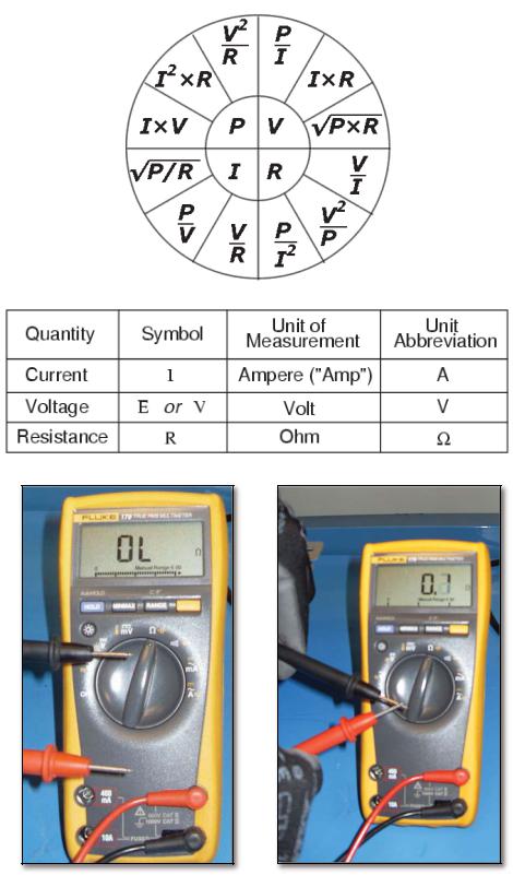
Troubleshooting Using Resistance - Ohm’s Law
OHM’S LAW
The direct current flowing in a conductor is directly proportional to the potential difference between its ends. It is usually formulated as V=IR, where V is the potential difference, or voltage, I is the current, and R is the resistance of the conductor.
CONTINUITY
22 |
Manufactured under one or more of these patents. U.S. Patents: 5332944, 5361215, 5550753, 5559720, 5,883,459, 6253227, 6282370, 6590188, 6976052, 6965815, 7030343, 7,417, |
834 b2, |
5/02/13 |
Canadian Patent: 2342614, Australian patent: 2373248 other patents both foreign and domestic applied for and pending. All material copyright of Balboa Water Group. |
|
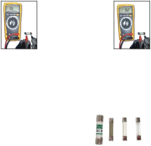
Testing a Fuse: Continuity
NOTE: THERE ARE NO SERVICEABLE PARTS ON THE PCB.
THE PREFERRED WAY TO CHECK FOR FUSE CONTINUITY IS WITH
THE FUSES REMOVED FROM THE CIRCUIT.
A FUSE WITH THE
METER READING “BAD”
TESTING A FUSE: CHECK CONTINUITY
WITH THE FUSE REMOVED
FUSES INSTALLED IN THE SYSTEM
0.3 amp |
(part number 21581) |
3 amp |
(part number 20600) |
10 amp |
(part number 30122) |
30 amp |
(part number 30136) |
A FUSE WITH THE
METER READING “GOOD”
42217B |
Manufactured under one or more of these patents. U.S. Patents: 5332944, 5361215, 5550753, 5559720, 5,883,459, 6253227, 6282370, 6590188, 6976052, 6965815, 7030343, 7,417, |
834 b2, |
Canadian Patent: 2342614, Australian patent: 2373248 other patents both foreign and domestic applied for and pending. All material copyright of Balboa Water Group. |
23 |

Troubleshooting Heater Resistance
TEST IS WITH POWER OFF
TROUBLESHOOTING HEATER RESISTANCE
Release tab
|
Release tab |
|
|
|
|
|
|
Locate the heater connector. |
Pull the connector straight out. |
||
Disconnect the connector by depressing the tab. |
|
|
|
|
ACCEPTABLE HEATER OHM (Ω) RANGES |
||
|
Heater Type |
Ohms (Ω) |
|
|
5.5 kW @ 240 V |
9.42 Ω-11.52 Ω |
|
|
4 kW @ 240 V |
12.96 Ω-15.84 Ω |
|
|
1 kW @ 120 V |
12.96 Ω- 15.84 Ω |
|
**Note: 1 kΩ= 1000 Ω :
kΩ may vary +/- 10% depending on the accuracy of the meter used.
Place the meter probes on the heater terminals.
24 |
Manufactured under one or more of these patents. U.S. Patents: 5332944, 5361215, 5550753, 5559720, 5,883,459, 6253227, 6282370, 6590188, 6976052, 6965815, 7030343, 7,417, |
834 b2, |
5/02/13 |
Canadian Patent: 2342614, Australian patent: 2373248 other patents both foreign and domestic applied for and pending. All material copyright of Balboa Water Group. |
|

Troubleshooting Heater Posts Resistance to Heater Housing
TEST IS WITH POWER OFF
TROUBLESHOOTING HEATER POSTS RESISTANCE TO HEATER HOUSING
VERIFY THAT THERE IS NO HEATER “LEAKAGE”
Release tab
Release tab
Locate the heater connector. |
Pull the connector straight out. |
Disconnect the connector by depressing the tab. |
|
Measure resistance from a heater post to the heater housing
Verify there is NO continuity from the heater post to the heater housing or heater current collector connection. The meter reading shown is OL, indicating infinite resistance.
Verify there is NO continuity from the heater post to the ground/earth. On the resistance scale, the a digital meter should read OL (indicating infinite resistance).
42217B |
Manufactured under one or more of these patents. U.S. Patents: 5332944, 5361215, 5550753, 5559720, 5,883,459, 6253227, 6282370, 6590188, 6976052, 6965815, 7030343, 7,417, |
834 b2, |
Canadian Patent: 2342614, Australian patent: 2373248 other patents both foreign and domestic applied for and pending. All material copyright of Balboa Water Group. |
25 |
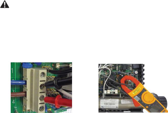
Troubleshooting with Voltage
IMPORTANT!
BEFORE TESTING A SPA CONTROL SYSTEM FOR VOLTAGE OR AMPERAGE, BE SURE OF THE FOLLOWING DANGERS:
HIGH AND LOW VOLTAGE CAN KILL.
QUALIFIED TECHNICIANS SHOULD BE PERFORMING THESE TESTS
OR
WHEN TESTING VOLTAGE |
WHEN TESTING AMPERAGE |
OBSERVE SAFETY AT ALL TIMES
26 |
Manufactured under one or more of these patents. U.S. Patents: 5332944, 5361215, 5550753, 5559720, 5,883,459, 6253227, 6282370, 6590188, 6976052, 6965815, 7030343, 7,417, |
834 b2, |
5/02/13 |
Canadian Patent: 2342614, Australian patent: 2373248 other patents both foreign and domestic applied for and pending. All material copyright of Balboa Water Group. |
|
 Loading...