

Page 1
ORION® Endpoint Utility
Software Application 2.5 for Trimble® Ranger 3
ORI-UM-00802-EN-01 (April 2014)
User Manual
Page 2

Page ii April 2014ORION® Endpoint Utility for Trimble® Ranger 3
Page 3

CONTENTS
INTRODUCTION . . . . . . . . . . . . . . . . . . . . . . . . . . . . . . . . . . . . . . . . . . . . . . . . . . . . . . . . . . . . . . . 5
USER GUIDE
PROGRAM STARTUP AND EXIT . . . . . . . . . . . . . . . . . . . . . . . . . . . . . . . . . . . . . . . . . . . . . . . . . . . . . 8
Onscreen Keyboard . . . . . . . . . . . . . . . . . . . . . . . . . . . . . . . . . . . . . . . . . . . . . . . . . . . . . . . . . 10
Title Bar . . . . . . . . . . . . . . . . . . . . . . . . . . . . . . . . . . . . . . . . . . . . . . . . . . . . . . . . . . . . . . . . . 10
ORION ENDPOINT UTILITY MENU . . . . . . . . . . . . . . . . . . . . . . . . . . . . . . . . . . . . . . . . . . . . . . . . . . 11
SETTING COM PORTS . . . . . . . . . . . . . . . . . . . . . . . . . . . . . . . . . . . . . . . . . . . . . . . . . . . . . . . . . . 12
ORION IR PROGRAMMING . . . . . . . . . . . . . . . . . . . . . . . . . . . . . . . . . . . . . . . . . . . . . . . . . . . . . . . 13
Performing an IR Read on an ORION Endpoint . . . . . . . . . . . . . . . . . . . . . . . . . . . . . . . . . . . . . . . . 13
ORION Cellular Endpoint IR . . . . . . . . . . . . . . . . . . . . . . . . . . . . . . . . . . . . . . . . . . . . . . . . . . . . 14
Magnet Swipe Warning for IR Access ......................................................................................................................................15
Force Read .........................................................................................................................................................................................15
Ping ......................................................................................................................................................................................................15
Modem Info ......................................................................................................................................................................................16
Mode ...................................................................................................................................................................................................16
ORION Migratable Endpoint IR . . . . . . . . . . . . . . . . . . . . . . . . . . . . . . . . . . . . . . . . . . . . . . . . . . 17
Start, Pause, Stop – Radio Modes ............................................................................................................................................19
IR Programming an ORION Migratable Endpoint (RTR) ....................................................................................................20
IR Force Read (HR-E LCD, HR-E, ADE) ......................................................................................................................................22
Listen ...................................................................................................................................................................................................22
Extended Status ..............................................................................................................................................................................23
RTR Extended Status .....................................................................................................................................................................24
ENC Extended Status .....................................................................................................................................................................25
High Resolution (HR) E LCD Extended Status .......................................................................................................................26
High Resolution (HR) E-Series Extended Status...................................................................................................................27
IR Programming Meter Size, Type and Units of Measure (RTR, ADE) ..........................................................................28
Advanced IR Programming ......................................................................................................................................................... 29
Setting GPS Location Manually .................................................................................................................................................30
Set Date and Time ..........................................................................................................................................................................31
Get Battery Status ...........................................................................................................................................................................31
Starting a Flow Rate Study ..........................................................................................................................................................31
IR Programming an ORION Migratable Gas Endpoint ......................................................................................................32
ORION Classic Endpoint IR . . . . . . . . . . . . . . . . . . . . . . . . . . . . . . . . . . . . . . . . . . . . . . . . . . . . . 34
Start, Pause, Stop - Radio Modes ..............................................................................................................................................35
Page iii April 2014 ORION® Endpoint Utility for Trimble® Ranger 3
Page 4

IR Programming an ORION Classic Endpoint (RTR) ............................................................................................................36
IR Force Read (ADE) ........................................................................................................................................................................37
Listen ...................................................................................................................................................................................................37
IR Programming an ORION Classic Gas Endpoint ...............................................................................................................38
Possible Drive Circles .....................................................................................................................................................................39
Reprogramming a Gas Drive Circle .........................................................................................................................................40
ORION QUICK READ . . . . . . . . . . . . . . . . . . . . . . . . . . . . . . . . . . . . . . . . . . . . . . . . . . . . . . . . . . . 42
ORION Quick Read-All . . . . . . . . . . . . . . . . . . . . . . . . . . . . . . . . . . . . . . . . . . . . . . . . . . . . . . . 43
ORION Quick Read-Single . . . . . . . . . . . . . . . . . . . . . . . . . . . . . . . . . . . . . . . . . . . . . . . . . . . . . 46
ORION PROFILE EXTRACTION . . . . . . . . . . . . . . . . . . . . . . . . . . . . . . . . . . . . . . . . . . . . . . . . . . . . .48
Prole Extraction - IR. . . . . . . . . . . . . . . . . . . . . . . . . . . . . . . . . . . . . . . . . . . . . . . . . . . . . . . . .49
Prole Extraction - RF . . . . . . . . . . . . . . . . . . . . . . . . . . . . . . . . . . . . . . . . . . . . . . . . . . . . . . . . 50
Transfer Proles . . . . . . . . . . . . . . . . . . . . . . . . . . . . . . . . . . . . . . . . . . . . . . . . . . . . . . . . . . . . 53
ORION NETWORK COMMUNICATION TEST. . . . . . . . . . . . . . . . . . . . . . . . . . . . . . . . . . . . . . . . . . . . .54
Network Communication Test - ORION Cellular Endpoint . . . . . . . . . . . . . . . . . . . . . . . . . . . . . . . . . 55
Network Communication Test - ORION Fixed Network and Migratable Endpoints . . . . . . . . . . . . . . . . . .57
ESERIES ULTRASONIC . . . . . . . . . . . . . . . . . . . . . . . . . . . . . . . . . . . . . . . . . . . . . . . . . . . . . . . . . . 60
SETTINGS . . . . . . . . . . . . . . . . . . . . . . . . . . . . . . . . . . . . . . . . . . . . . . . . . . . . . . . . . . . . . . . . . . 62
Hardware Settings . . . . . . . . . . . . . . . . . . . . . . . . . . . . . . . . . . . . . . . . . . . . . . . . . . . . . . . . . . 63
Logging Options . . . . . . . . . . . . . . . . . . . . . . . . . . . . . . . . . . . . . . . . . . . . . . . . . . . . . . . . . . . 66
Prole Extraction Defaults . . . . . . . . . . . . . . . . . . . . . . . . . . . . . . . . . . . . . . . . . . . . . . . . . . . . . 67
APPENDIX
GLOSSARY. . . . . . . . . . . . . . . . . . . . . . . . . . . . . . . . . . . . . . . . . . . . . . . . . . . . . . . . . . . . . . . . . .70
CONNECTING AN EXTERNAL MOBILE TRANSCEIVER OR RECEIVER . . . . . . . . . . . . . . . . . . . . . . . . . . . . . 71
USING THE HANDHELD KEYPAD . . . . . . . . . . . . . . . . . . . . . . . . . . . . . . . . . . . . . . . . . . . . . . . . . . . 72
HANDHELD FACTORY RESET/CLEAN BOOT . . . . . . . . . . . . . . . . . . . . . . . . . . . . . . . . . . . . . . . . . . . . 73
IR PROGRAMMING BRACKET. . . . . . . . . . . . . . . . . . . . . . . . . . . . . . . . . . . . . . . . . . . . . . . . . . . . . . 74
STATUS CODES . . . . . . . . . . . . . . . . . . . . . . . . . . . . . . . . . . . . . . . . . . . . . . . . . . . . . . . . . . . . . . . 75
VALID COM PORTS . . . . . . . . . . . . . . . . . . . . . . . . . . . . . . . . . . . . . . . . . . . . . . . . . . . . . . . . . . . . 75
GAS METER DRIVE ROTATION . . . . . . . . . . . . . . . . . . . . . . . . . . . . . . . . . . . . . . . . . . . . . . . . . . . . . 76
TECHNICAL SUPPORT . . . . . . . . . . . . . . . . . . . . . . . . . . . . . . . . . . . . . . . . . . . . . . . . . . . . . . . . . . 77
Page iv April 2014ORION® Endpoint Utility for Trimble® Ranger 3
Page 5

INTRODUCTION
INTRODUCTION
The ORION® Endpoint Utility 2.5.x is a software application designed for reading and programming water and gas
ORION endpoints with the Trimble® Ranger 3 handheld computer. This manual is the guide for using the ORION
Endpoint Utility software application.
Audience and Purpose
The ORION Endpoint Utility for the Trimble Ranger 3 User Manual is intended to be used by field technicians who program
and quick read ORION endpoints and access meter profile data.
OTE:N To provide the best solution for our customers, Badger Meter continually improves software programs and updates
this manual periodically to reflect upgrades. Therefore, some discrepancies may be detected between the installed
software and this manual.
System Overview
The Trimble Ranger 3 handheld computer is a flexible, easy-to-use tool that can be used with various meter reading
technologies. It provides utilities with a handheld interrogator that can be operated with a touch screen and the customized
keypad for data entry.
The handheld is compatible with ORION manual and touch read systems, including the following ORION endpoints.
• The ORION Cellular endpoint is a two-way water endpoint that utilizes existing cellular infrastructure to efficiently
and securely deliver meter reading data to the utility via the cellular network.
• The ORION Fixed Network endpoint (SE) is a full functioning two-way endpoint for use in either mobile or fixed
network mode of operation. Once installed, ORION Fixed Network endpoints operate in mobile mode and
automatically transition to fixed network mode of operation when ORION network gateway transceivers and reading
data management software are deployed. ORION Fixed Network endpoints automatically transition to a backup
mobile mode of operation if the network is disrupted for a period of time.
OTE:N In fixed network priority mode, ORION Fixed Network endpoints with 1.12 firmware and later transmit a
mobile message every 10 seconds.
• The ORION Migratable endpoint (ME) is a full functioning two-way endpoint for mobile applications with the
capability of migrating to fixed network mode to support future utility growth. In addition to providing the current
reading, the two-way functionality of the ORION Migratable endpoint allows users to capture data profile information
wirelessly, without having to access the endpoint during the normal reading process.
• The ORION Classic endpoint (CE) is a one-way endpoint designed for mobile meter reading. ORION Classic endpoints
support data profile and may be transitioned to fixed network application through approved electric connectivity
partner solutions, or with strategic deployment of ORION gateway 4.0 and 2.0 receivers.
About This Manual
• User Guide
The User Guide has instructions for program startup and exit, and step-by-step instructions for using the ORION
Endpoint Utility software application functions, including endpoint programming, profile extraction and quick read.
For the complete list of functions, see the "ORION Endpoint Utility Menu" onpage11.
• Appendix
See the Appendix for a glossary of terms, handheld information, valid COM ports, status codes, gas meter drive
rotation list and Badger Meter Technical Support contact information.
OTE:N For software installation and removal instructions, refer to the Trimble Ranger 3 Meter Reading System ORION
Software Installation Manual, which can be found at www.badgermeter.com.
Page 5 April 2014 ORION® Endpoint Utility for Trimble® Ranger 3
Page 6

INTRODUCTION
Typographic Conventions
• Items on the software screens that you need to select or choose by clicking a button, highlighting, checking a box or
another similar means are in bold text and capitalized in the manual.
Example: Click the View Report button.
• Names of options, boxes, columns and fields are italicized. In most cases, first letters will be capitalized.
Example: The value displays in the Status Information field.
• Messages and special markings are shown in quotation marks.
Example: “Service Stopped” is shown on the display.
OTE:N Names, addresses and other customer-related information displayed in screen examples were created for
demonstration purposes in this manual. No actual customer information is included.
Page 6 April 2014ORION® Endpoint Utility for Trimble® Ranger 3
Page 7

USER GUIDE
USER GUIDE
Page 7 April 2014 ORION® Endpoint Utility for Trimble® Ranger 3
Page 8
PROGRAM STARTUP AND EXIT
PROGRAM STARTUP AND EXIT
1. Press the green power key on the keypad to turn on the handheld.
2. At the Windows® home screen, tap the Start button
in the left corner of the navigation bar at the bottom
of the screen.
Windows Start
button
3. Tap once on the folder labeled Badger Field
Applications.
Figure 1: Windows home
Result: The Badger Field Applications folder opens.
OTE:N To rearrange the icons on the screen, touch
and hold an icon, then drag the icon to the
location you prefer.
OTE:N Badger Field Applications includes a
suite of meter reading software products.
This manual includes descriptions and
instructions for using the ORION Endpoint
Utility software.
For more information, refer to the user
manual titled, ORION Automated Reading
System for Trimble Ranger 3, available at
www.badgermeter.com.
Figure 2: Badger Field Applications folder
4. Tap the ORION Endpoint Utility icon.
Result: The Verify Date and Time screen opens.
Figure 3: ORION Endpoint Utility
Page 8 April 2014ORION® Endpoint Utility for Trimble® Ranger 3
Page 9
5. Verify the date and time shown on the screen
are correct.
If the date and time are correct, tap Ok and continue
with Step 6.
MPORTANTI
The date and time on the handheld must be
accurate to ensure communication with
ORION Migratable (and Fixed Network in mobile
mode) endpoints.
If the date and/or time need to be adjusted, go to
Windows Start> Settings> Clocks & Alarms on
the handheld.
Result: The Clock & Alarms screen opens (Figure 5).
Adjust the time zone, date and/or time, as needed.
When finished tap OK. Then tap the X to close the
Settings screen and return to the ORION Endpoint
Utility software.
PROGRAM STARTUP AND EXIT
Figure 4: Verify date and time
OTE:N The first time the software is accessed,
the License Agreement screen (Figure 6)
opens automatically, after the
Clock Verification screen.
Read the software license agreement
and tap I Accept. The License Agreement
must be accepted by an authorized
representative of the customer/licensee.
The License Agreement screen
closes automatically.
To see the License Agreement at any time,
tap View License on the sign in screen.
Figure 5: Adjust time zone, date and/or time
Figure 6: Accept license agreement
Page 9 April 2014 ORION® Endpoint Utility for Trimble® Ranger 3
Page 10
PROGRAM STARTUP AND EXIT
6. Once the time and date are veried, the ORION
Endpoint Utility sign in screen opens.
You can also view trademarks and license or select
language on this screen.
7. Enter a three to ve character personal identication
number (PIN) using the keypad. The Ok button
becomes active.
OTE:N The PIN must be entered by an authorized
representative of the customer/licensee.
The PIN is user defined and can be a name,
initials, an ID number or other information.
8. Tap Ok to access the ORION Endpoint Utility
menu screen.
9. To exit the ORION Endpoint Utility software, tap the
Exit button. If the Exit button does not display in
the navigation bar of the screen, tap Menu> Exit.
Onscreen Keyboard
Figure 7: Type PIN
Tap to
exit the
software
The center icon at the bottom of most ORION Endpoint Utility
screens gives you access to the onscreen keyboard as shown
in Figure 8.
The keyboard can be used to enter information into screen
elds as an alternative to using the handheld keypad.
Tap the icon to open the keyboard whenever you want to use
it. Tap the icon again to close the keyboard.
Tap for
onscreen
keyboard
Title Bar
When you sign in, the title bar of the ORION Endpoint Utility
software displays the name of the software. The title bar changes to
show the selected function or the type of endpoint being read.
In addition, the color of the title bar on the ORION Endpoint Utility
screens indicates battery charging status.
Figure 8: Onscreen keyboard
• Green = > 65% charged
• Red = < 35% charged
• Yellow = 35…65% charged
• Blue = handheld is charging
Tap the title bar to see the battery status percentage (Figure 9).
Figure 9: Battery status in title bar
Page 10 April 2014ORION® Endpoint Utility for Trimble® Ranger 3
Page 11
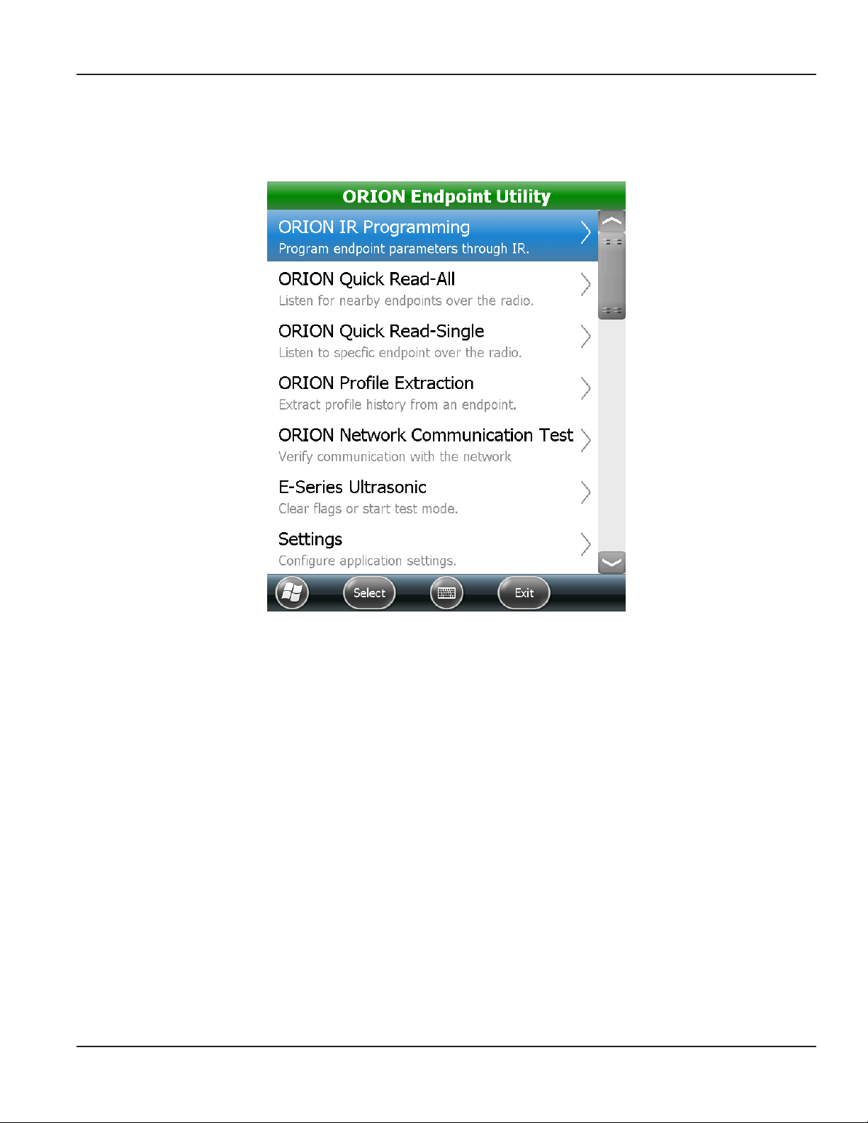
ORION ENDPOINT UTILITY MENU
ORION ENDPOINT UTILITY MENU
A menu of the ORION Endpoint Utility options is shown on the main screen. An expanded view is shown in Figure 10. On the
handheld, scroll to see all the menu options.
Figure 10: ORION Endpoint Utility menu
The ORION Endpoint Utility performs multiple functions.
• Programs and quick reads ORION Cellular, Migratable and Classic water and gas endpoints.
• Extracts additional information from ORION Migratable endpoints including historical interval data and
extended status.
• Verifies network communications for ORION Cellular and Fixed Network endpoints.
• Increases the test sampling rate of E-Series meters.
Page 11 April 2014 ORION® Endpoint Utility for Trimble® Ranger 3
Page 12
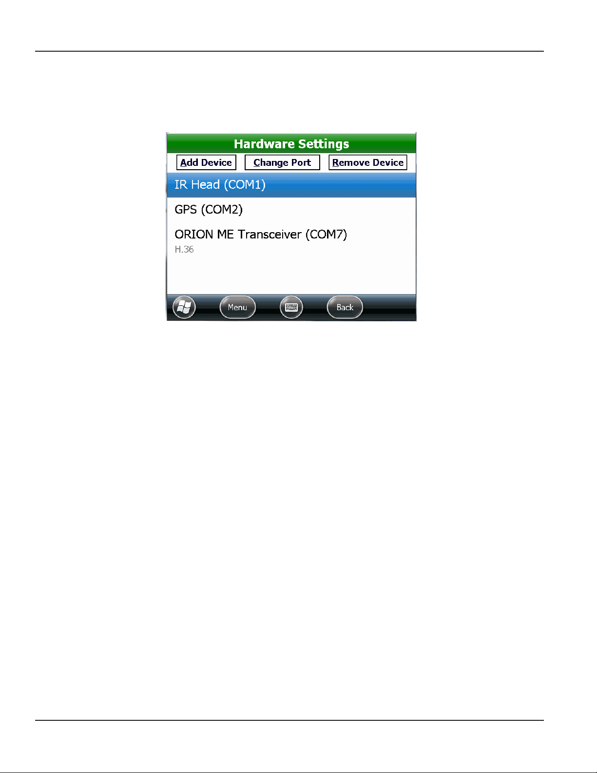
SETTING COM PORTS
SETTING COM PORTS
Before you start using the ORION Endpoint Utility functions, go to Settings> Hardware Settings to set the COM ports for the
equipment attached to the handheld.
Figure 11: Hardware settings default
The example in Figure 11 shows the Hardware Settings screen for a handheld with built-in GPS, internal ORION Migratable
transceiver and IR programming cable attached to the handheld nine-pin serial port. For more information, see "Hardware
Settings" onpage63.
For a list of valid COM ports, see "Valid COM Ports" onpage75.
Page 12 April 2014ORION® Endpoint Utility for Trimble® Ranger 3
Page 13

ORION IR PROGRAMMING
ORION IR PROGRAMMING
The ORION IR Programming function is used to read and program ORION water and gas endpoints using the IR programming
cable. This function is also used to program an endpoint following a tamper repair or retrofit installation (RTR® water
installations only) as well as perform a variety of other functions.
This section has instructions for performing the IR functions for each endpoint type: ORION Cellular, Migratable and Classic.
OTE:N To facilitate IR functions, an optional IR head alignment tool is available. For more information, see "IR Programming
Bracket" onpage74.
MPORTANTI
The IR programming cable must be attached to the handheld with the COM port correctly set. Align the IR optical head
with the endpoint IR LED port to perform the functions described in this section.
Performing an IR Read on an ORION Endpoint
1. Select the ORION IR Programming function from the ORION Endpoint Utility menu.
OTE:N The screen shown in Figure 12 displays the first time you sign in to the ORION Endpoint Utility and select the
ORION IR Programming function. Once an endpoint is read, the IR Programming screen displays instead as
shown in Figure 13 on the next page. The screen refreshes each time you Read a new endpoint.
Title bar displays
the function you
selected
Tap to read an
ORION endpoint
Navigation and
onscreen keyboard
buttons display at the
bottom of the screen
Figure 12: Access IR functions
ORION Cellular endpoints only
Before reading the endpoint, swipe the magnet along the side of the endpoint where the serial number and bar code
are engraved to place the endpoint in IR mode. The endpoint LED flashes while in IR mode and stays in IR mode for
approximately two minutes.
2. Align the IR optical head with the endpoint IR LED port.
3. Tap the Press to read button.
Result: The IR Programming screen displays showing endpoint information including endpoint and encoder type. See the
example in Figure 13.
Page 13 April 2014 ORION® Endpoint Utility for Trimble® Ranger 3
Page 14
ORION IR PROGRAMMING
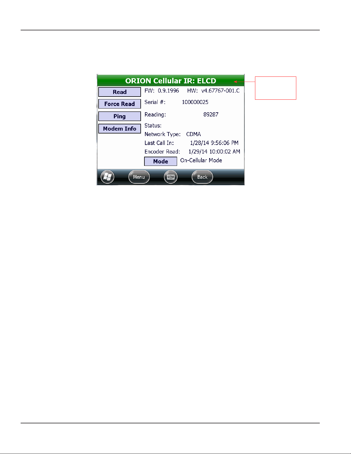
ORION Cellular Endpoint IR
Select the ORION IR Programming function to read ORION Cellular water endpoints. ORION Cellular endpoints cannot be
field programmed but the IR Programming function is used to perform a force read of the endpoint to the encoder and ping
to confirm endpoint network communication.
Title bar displays
the endpoint
technology
Figure 13: IR Programming screen for ORION Cellular endpoint
OTE:N Prior to performing any of the ORION Cellular endpoint IR functions, connect the IR programming cable to the
handheld and make sure the COM port is set. See "Hardware Settings" onpage63 if you need help.
ORION Cellular Endpoint IR Buttons
Read Initiates IR communication between the handheld and the endpoint. Reads the endpoint type and
displays the information for the specific endpoint.
Force Read Used to update the real-time encoder odometer value on the endpoint.
Ping Used to confirm endpoint communication with BEACON AMA software.
Modem Info Displays the modem properties. Modem properties refresh each time the button is selected.
Mode Displays the current state of the endpoint. See "Mode" onpage16 for a list of the endpoint modes that
can display in this field.
OTE:N The Mode button is for troubleshooting only. Do not access unless authorized by Badger Meter
Technical Support.
ORION Cellular Endpoint IR Fields
Title Bar
FW
Displays the endpoint and encoder type.
Displays the endpoint firmware version.
HW Displays the endpoint hardware version.
Serial # Displays the serial number of the ORION Cellular endpoint.
Reading Displays the endpoint raw reading value.
Status Displays the endpoint exception status. Options are T (Tamper) and EE (Encoder Error). The field is blank
when there is no Status to display.
Network Type Displays the radio system used by the ORION Cellular endpoint.
Last Call In Date and time of the last successful endpoint communication to BEACON.
Encoder Read Date and time of the last encoder reading received by the endpoint.
Page 14 April 2014ORION® Endpoint Utility for Trimble® Ranger 3
Page 15
ORION IR PROGRAMMING
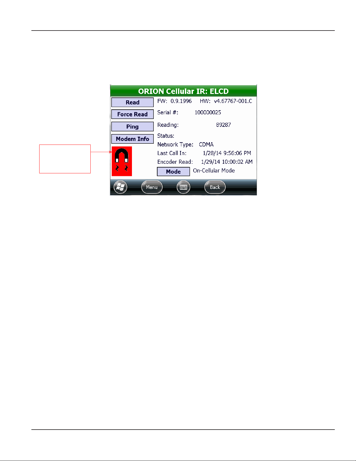
Magnet Swipe Warning for IR Access
To place an ORION Cellular endpoint in IR mode, swipe the magnet along the side of the endpoint where the serial number
and bar code are engraved. The LED flashes and the endpoint stays in IR mode for approximately two minutes.
After approximately two minutes, the magnet icon flashes on the IR Programming screen (Figure 14) as a reminder to swipe
the magnet again to perform additional IR functions.
Icon displays/flashes
as a reminder that
a magnet swipe is
required for IR access
Figure 14: Endpoint requires magnet swipe for IR mode
Force Read
Tap Force Read to update the real-time encoder odometer value on the endpoint. The ORION Cellular endpoint is compatible
with Badger Meter high resolution encoders and Badger Meter approved three-wire encoders. The ORION Cellular endpoint is
not compatible with RTR encoders. For complete information, refer to the ORION Cellular Endpoints product data sheet which
can be found at www.badgermeter.com.
1. To perform a Force Read, align the optical head of the IR cable with the ORION Cellular endpoint IR LED port. You may
need to perform a magnet swipe on the ORION Cellular endpoint to activate IR communication.
2. On the ORION IR Programming screen, tap Read to read the endpoint.
3. Tap Force Read.
Result: The reading value updates to reect the current encoder odometer value. A reading will display if the tamper
condition no longer exists.
Ping
1. To Ping an ORION Cellular endpoint, align the optical head of the IR cable with the ORION Cellular endpoint IR LED
port. You may need to perform a magnet swipe on the ORION Cellular endpoint to activate IR communication.
2. On the ORION IR Programming screen, tap Read to read the endpoint.
3. Tap Ping to conrm an endpoint network connection. For complete information, see "ORION Network Communication
Test" onpage54.
Page 15 April 2014 ORION® Endpoint Utility for Trimble® Ranger 3
Page 16
ORION IR PROGRAMMING
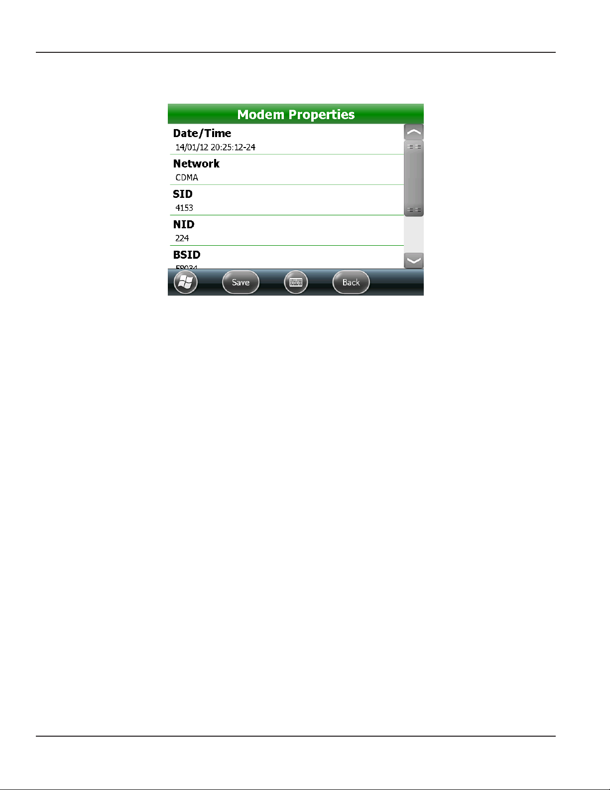
Modem Info
Select Modem Info on the IR Programming screen to display the Modem Properties for the ORION Cellular endpoint.
Figure 15: Cellular endpoint modem properties
1. Align the optical head of the IR cable with the ORION Cellular endpoint IR LED port. You may need to perform a
magnet swipe on the ORION Cellular endpoint to activate IR communication.
2. On the ORION IR Programming screen, tap Read to read the endpoint.
3. Tap Modem Info.
Result: The Modem Properties screen opens.
Scroll to see all the information on the screen. Tap Back to return to the IR Programming screen. The information refreshes
each time you tap Modem Info.
OTE:N The Save button is for Technical Support use only.
Mode
The Mode field can display the following statuses for the ORION Cellular endpoint.
On Cellular Mode Endpoint is initialized and communicating with BEACON.
Provision Mode Endpoint initialization failed to communicate with BEACON. The endpoint will attempt to establish a
connection at its normally scheduled transmit time.
Stopped Endpoint communications stopped.
MPORTANTI
The Mode button is used to Stop the endpoint and should only be selected when instructed to by Badger Meter
Technical Support.
Page 16 April 2014ORION® Endpoint Utility for Trimble® Ranger 3
Page 17
ORION IR PROGRAMMING
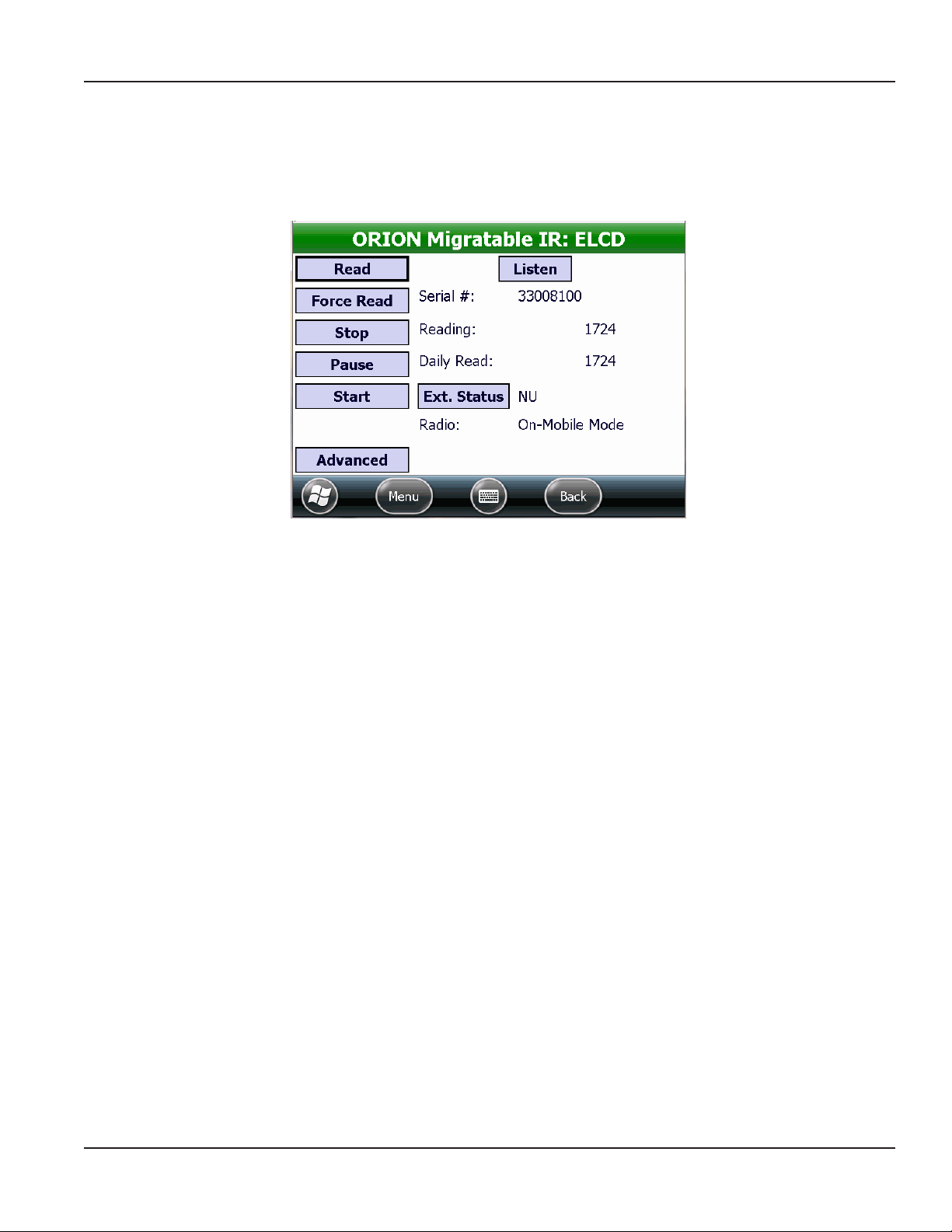
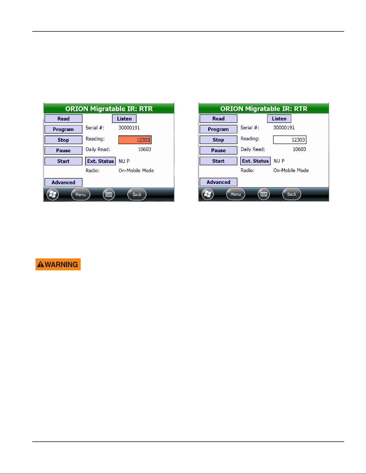
ORION Migratable Endpoint IR
Select the ORION IR Programming function to read ORION Migratable (or Fixed Network in mobile mode) water and gas
endpoints. This function is also used to program an endpoint following a tamper repair or retrofit installation (RTR® water
installations only) or perform a force read of the endpoint to the encoder, extract historical interval data, and confirm
endpoint network communication.
Figure 16: IR Programming screen for ORION Migratable endpoint
OTE:N Prior to performing any of the ORION Migratable endpoint IR functions, connect the IR programming cable to the
handheld, and make sure the appropriate COM port is set. See "Hardware Settings" onpage63 if you need help.
ORION Migratable Endpoint IR Buttons
Read Initiates the IR communication between the handheld and the endpoint. Reads the endpoint type and
displays the information for the specific endpoint.
Program/
Force Read
Stop Stops the endpoint from transmitting. A stopped endpoint must be reprogrammed to begin transmitting
Pause Pauses the endpoint transmission temporarily until a unit of water is registered.
Start Starts the endpoint transmission.
Ext Status Used to view endpoint exception statuses and additional information programmed into an endpoint. It is also
Advanced Displays the endpoint firmware version and type of registration. The Advanced screen also includes buttons
Listen Switches to radio frequency (RF) to ”hear“ if the endpoint is active and in mobile mode.
Toggles, depending on encoder type. When used with an RTR encoder, Program is used to set the endpoint
odometer value following a tamper repair. When used with an HR-E LCD or ADE® encoder, Force Read is used
to view the real-time encoder odometer value.
again. The endpoint history (profile data) is cleared when the ORION Migratable endpoint is restarted.
used to field program meter type and size and unit of measure.
to request additional endpoint information such as date and time, start and get results of a flow rate study
and get the endpoint battery status.
Change DC
(gas only)
Displays after initial read only for gas endpoints. Used to select the gas drive circle information.
Page 17 April 2014 ORION® Endpoint Utility for Trimble® Ranger 3
Page 18

ORION IR PROGRAMMING
ORION Migratable Endpoint IR Fields
Serial # Displays the serial number of the ORION Migratable or Fixed Network endpoint.
Reading Used to view the current endpoint reading value. For an RTR, it is used in conjunction with the Program
button to reprogram the odometer value after a tamper repair.
Daily Read Used to view the time-synchronized daily endpoint reading value.
Radio Used to view the endpoint radio transmission mode. Allows selection of another mode from an available list.
Status
(gas only)
Displays the full endpoint status which provides information regarding the programming and configuration
of the endpoint, including meter size, model type and units, as well as any alerts.
Page 18 April 2014ORION® Endpoint Utility for Trimble® Ranger 3
Page 19
ORION IR PROGRAMMING
Start, Pause, Stop – Radio Modes
ORION Migratable and Fixed Network endpoints are programmed at the factory to begin sending meter readings when the
register senses flow through the meter. As a result, the endpoints can be installed on meters without having to manually start
the endpoint. When water usage is registered on the meter, the endpoint sends a signal every 5…6 seconds. The following
statuses can display in the Radio field on the ORION Migratable IR Programming screen.
Stopped The endpoint is not transmitting. A stopped endpoint must be reprogrammed to begin transmitting
again. Stored historical endpoint interval data (profile data) is cleared when the endpoint is restarted.
Paused Endpoint is in non-transmission mode temporarily until a unit of water or gas is registered. Commonly
used for seasonal customer accounts.
On-Mobile Mode An ORION Migratable or Fixed Network endpoint begins in mobile mode and continues to transmit in
mobile mode until and unless communication is established with an ORION Fixed Network gateway
transceiver. An endpoint in mobile mode sends a message requesting gateway assignment once
every hour. If a gateway responds with an assignment using two-way communication, the endpoint
automatically switches to On-Fixed Mode. Fixed mode transmissions cannot be received by the
handheld transceiver.
Discovery Mode For troubleshooting only. To be used under the direction of Badger Meter Technical Support.
On-Fixed Mode An endpoint in On-Fixed Mode is assigned to an ORION Fixed Network gateway transceiver for data
collection. It reverts to On-Mobile Mode if the endpoint fails to receive a response from a gateway
for four consecutive days. Once communication is re-established with the gateway, the endpoint
automatically transitions to On-Fixed Mode.
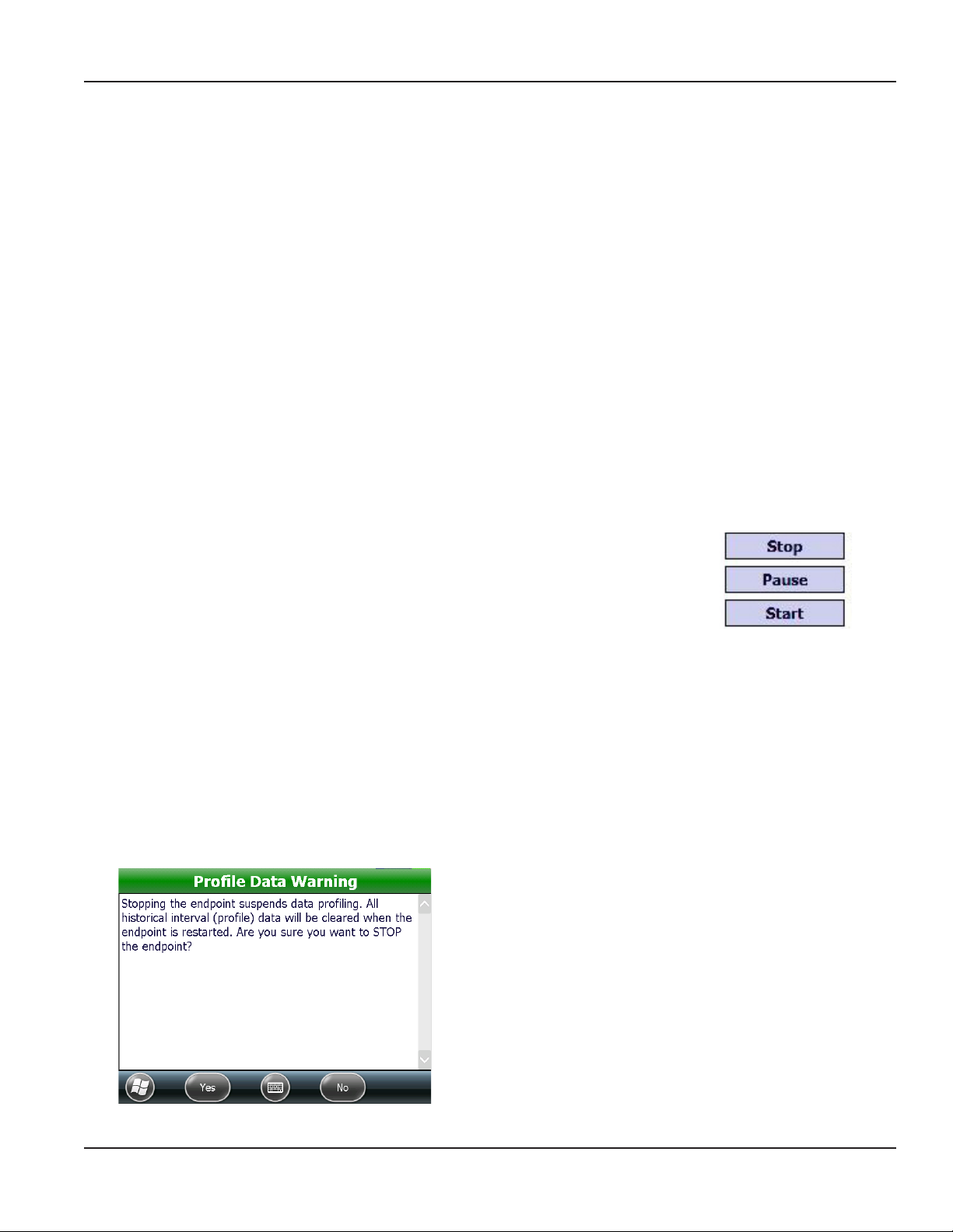
The Stop button suspends data profiling and stops an endpoint from sending a signal,
regardless of the usage registered from the meter. Align the optical head on the IR cable
with the endpoint IR LED port and tap Stop. Tap Start to turn the endpoint on again. The
endpoint history (profile data) is cleared when the endpoint is restarted. See Profile Data
Warning below.
The Pause button temporarily stops the radio signal. Align the optical head on the IR
cable with the endpoint IR LED port and tap Pause. The endpoint begins transmitting
again when a unit of water is registered from the meter.
The Start button is used to start an endpoint after it is Stopped or before usage is registered. Align the optical head on the IR
cable with the endpoint IR LED port and tap Start.
OTE:N Stopped radios must be restarted using the Start function and will not automatically restart when usage is registered
from the meter. When used with an RTR, the odometer value must also be programmed to reflect the current
registration reading. When used with an ADE, the odometer value is automatically updated within the hour.
OTE:N An ORION Migratable or Fixed Network endpoint connected to an ADE (or approved competitive three-wire encoder)
does not require programming to clear a tamper. After the wires have been repaired, the endpoint is automatically
updated to reflect the register odometer value in the first hour after the wires have been repaired.
Profile Data Warning
The warning screen shown here is displayed when you
tap Stop.
Stopping an endpoint suspends data profiling. Restarting
clears all historical interval data (profile data) and places fixed
mode endpoints into mobile mode. Endpoints in mobile
mode may not revert to fixed mode for up to 48 hours.
Figure 17: Radio modes
OTE:N It is not necessary to tap Stop / Start before and
Figure 18: Stop endpoint warning
after fixing a tamper.
Page 19 April 2014 ORION® Endpoint Utility for Trimble® Ranger 3
Page 20
ORION IR PROGRAMMING
IR Programming an ORION Migratable Endpoint (RTR)
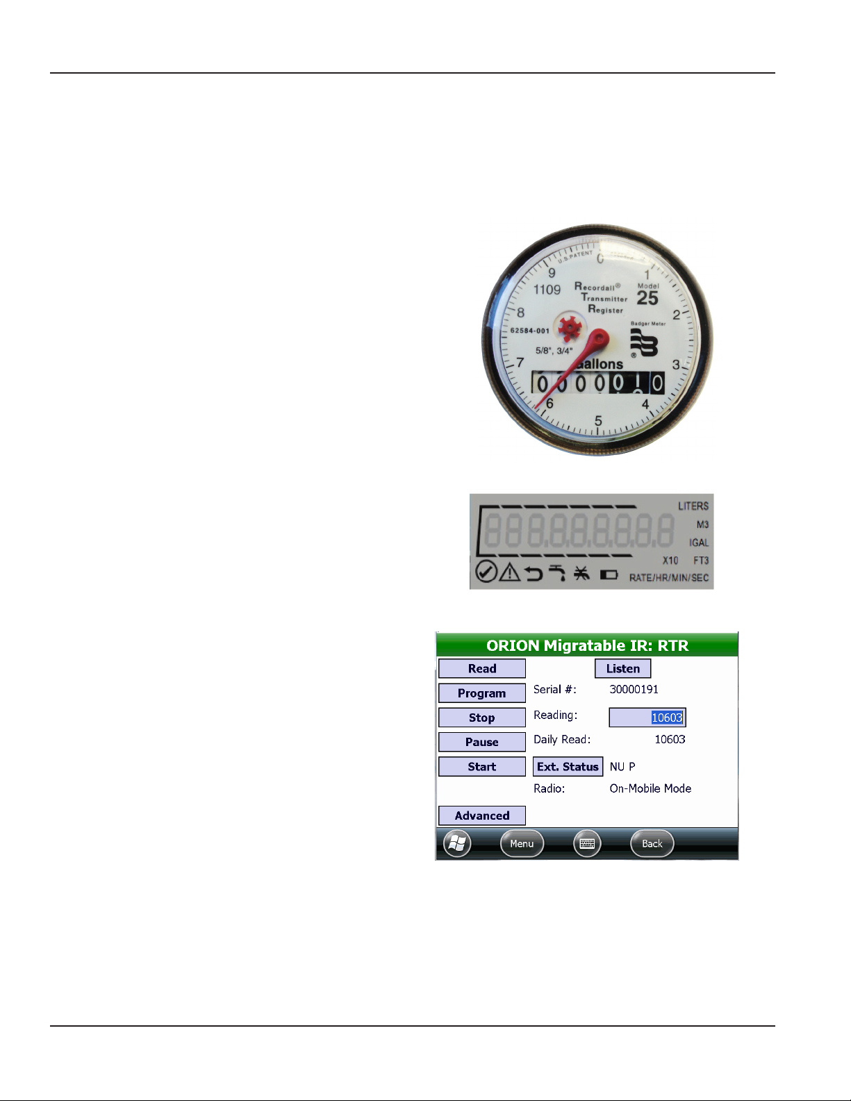
When used with an RTR encoder, you must program and set the endpoint odometer value following a tamper repair.
Reading the Odometer
To install an ORION Migratable endpoint on an active meter with usage on the RTR, use the following information to ensure
that the value in the endpoint matches the current odometer value on the RTR once the endpoint is connected to the RTR.
When programming ORION endpoints, enter the value of the
six moveable odometer wheels plus the sweep hand for all
meter types (gallons, cubic feet, etc.) and all meter models.
In Figure 19, the odometer value in the moveable dials (both
white and black digits) is "000001."
The sweep hand is pointing between the "6" and the “7" but
because the sweep hand has not yet hit the "7", use "6" as the
value for the last digit of the meter reading. Therefore, in this
example, the value to be entered into the ORION endpoint
Reading field would be "16" or "0000016." (The leading zeros
are not required.)
When programming an ORION endpoint connected to an
E-Series meter with an RTR protocol, program the seven most
significant (left-most) digits shown on the meter display.
OTE:N For instructions on programming a gas endpoint,
see "IR Programming an ORION Migratable Gas
Endpoint" onpage32.
1. Align the optical head of the IR cable with the
endpoint IR LED port and tap Read on the IR
Programming screen.
2. Double-tap the reading in the Reading eld.
Result: The current reading in the eld is highlighted
(Figure 21).
Figure 19: Odometer value
Figure 20: E-Series meter display
Figure 21: RTR Reading field
Page 20 April 2014ORION® Endpoint Utility for Trimble® Ranger 3
Page 21
ORION IR PROGRAMMING
3. Using the handheld keypad, enter the RTR odometer value in the Reading eld.
Result: The reading box is highlighted (Figure 22) to indicate a new value is entered in the eld but not yet programmed.
Leading zeros are not required, however it may be helpful to enter leading zeros as visual confirmation. Only seven
digits can be entered when programming an endpoint, regardless of the meter size.
4. Align the optical head of the IR cable with the ORION Migratable endpoint IR LED port and tap Program.
Result: The endpoint is programmed with the new value and the reading box is no longer highlighted. See Figure 23.
Figure 22: New reading entered
Figure 23: New reading programmed
OTE:N When programming an endpoint after clearing a tamper, verify that the programming and wire splicing were
successful. Select ORION Quick Read - Single from the Menu to perform a Quick Read on the endpoint. If the
endpoint still reports “Tamper” in the Status eld, check the wire splices, repair as necessary and then repeat the
programming procedure above.
DO NOT STOP AN ENDPOINT BEFORE FIXING A TAMPER. RESTARTING A STOPPED
ENDPOINT CLEARS THE HISTORICAL INTERVAL DATA PROFILE DATA AND PLACES FIXED
MODE ENDPOINTS INTO MOBILE MODE. ENDPOINTS IN MOBILE MODE MAY NOT REVERT
TO FIXED MODE FOR UP TO 48 HOURS.
Page 21 April 2014 ORION® Endpoint Utility for Trimble® Ranger 3
Page 22
ORION IR PROGRAMMING
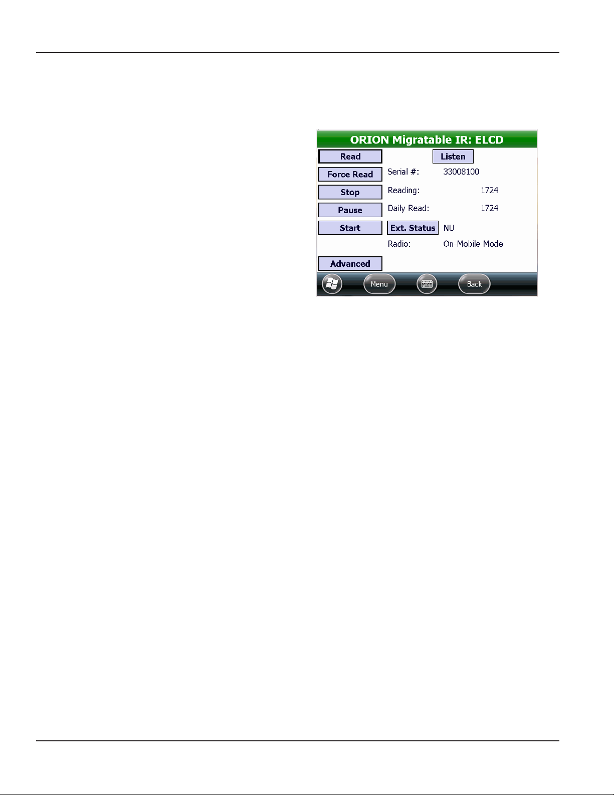
IR Force Read (HR-E LCD, HR-E, ADE)
When an ORION Migratable (or Fixed Network in mobile mode) endpoint connected to an HR-E LCD, HR-E or ADE encoder is
read, the Force Read button displays instead of the Program button on the IR Programming screen. Force Read is used to
view the real-time encoder odometer value and to verify a successful tamper repair.
1. Align the optical head of the IR cable with the
ORION Migratable endpoint IR LED port.
2. On the ORION IR Programming screen, tap Read to
read the endpoint.
3. Tap Force Read.
Result: The reading value updates to reect the current
encoder odometer value. A reading will display if the
tamper condition no longer exists.
Figure 24: Force Read on E LCD
Listen
OTE:N Prior to using the Listen function, make sure the handheld has a built in ORION Migratable transceiver or an external
mobile transceiver is connected and the appropriate COM port is set. See "Glossary" onpage70 if you need help.
Tap Listen to activate radio frequency (RF) and display the RF quick read information for the selected endpoint when in
mobile mode. For additional information, see "ORION Quick Read-Single" onpage46.
Page 22 April 2014ORION® Endpoint Utility for Trimble® Ranger 3
Page 23
ORION IR PROGRAMMING
Extended Status
The Ext Status button on the ORION IR Programming screen provides access to information which has been programmed
into an ORION Migratable endpoint.
Title bar displays
the endpoint type
and serial number
Figure 25: Extended Status - ADE
The type of technology displays across the bar at the top of the Extended Status screen. The status fields that display are
dependent on the technology. A check mark in a status field indicates a condition or alert that exists for the endpoint.
When pre-wired endpoint assemblies are factory programmed, the meter size and type and the units of measure display in
the fields. Meter size and type and the units of measure can also be field programmed for RTR and ENC endpoints.
Examples of the Extended Status screen for the different technology types (RTR, ENC, E LCD, E-Series) are shown on the next
four pages.
Page 23 April 2014 ORION® Endpoint Utility for Trimble® Ranger 3
Page 24
ORION IR PROGRAMMING
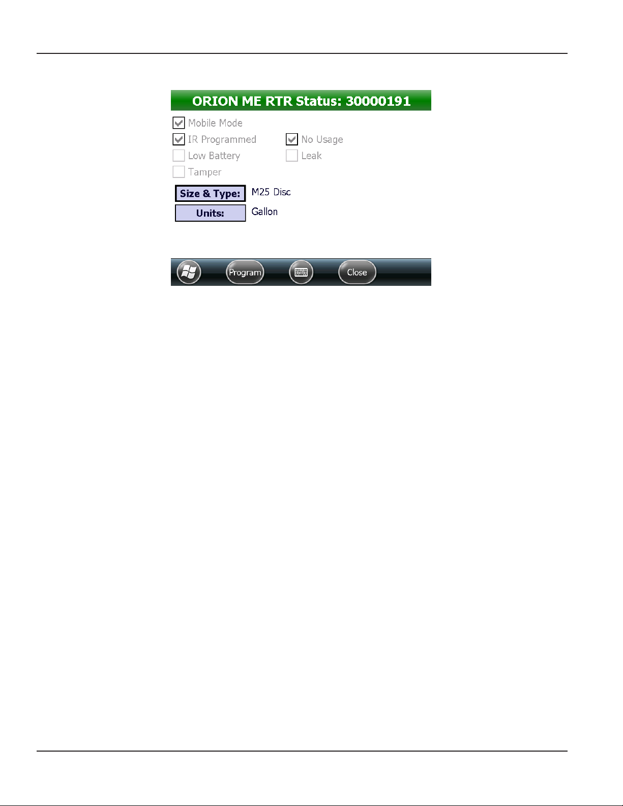
RTR Extended Status
Figure 26: Extended Status- RTR
The status indicators described below apply for an ORION Migratable (or Fixed Network in mobile mode) endpoint when
connected to an RTR.
Status Indicator Description
Mobile Mode Endpoint is communicating in mobile transmission mode.
IR Programmed Endpoint has been reprogrammed via IR.
Low Battery Endpoint is reporting a low battery condition.
Tamper Endpoint is reporting a tamper condition. This condition occurs when the wire between the register
and the endpoint is cut or shorted, or the RTR is not connected. See "" onpage19 for instructions
on clearing the tamper.
No Usage Endpoint is reporting a no usage condition. This condition occurs when there is no water flow
registered over a 30-day time frame.
Leak Endpoint is reporting a potential leak condition when there is continuous usage over a 24-hour time
period without a 1-hour period of non-usage.
Encoder Information Description
Size & Type The size and type of the meter for which the RTR was programmed. Tap the button to change the
size and type. See "IR Programming Meter Size, Type and Units of Measure (RTR, ADE)" onpage28 for
more information.
Units The units of measure as defined by the RTR: cubic meters, cubic feet, gallons, imperial gallons or
liters. Tap the button to change the units. See "IR Programming Meter Size, Type and Units of Measure
(RTR, ADE)" onpage28 for more information.
OTE:N Refer to the ORION Migratable Endpoint product data sheet, available at www.badgermeter.com, for
complete information.
Page 24 April 2014ORION® Endpoint Utility for Trimble® Ranger 3
Page 25

ORION IR PROGRAMMING
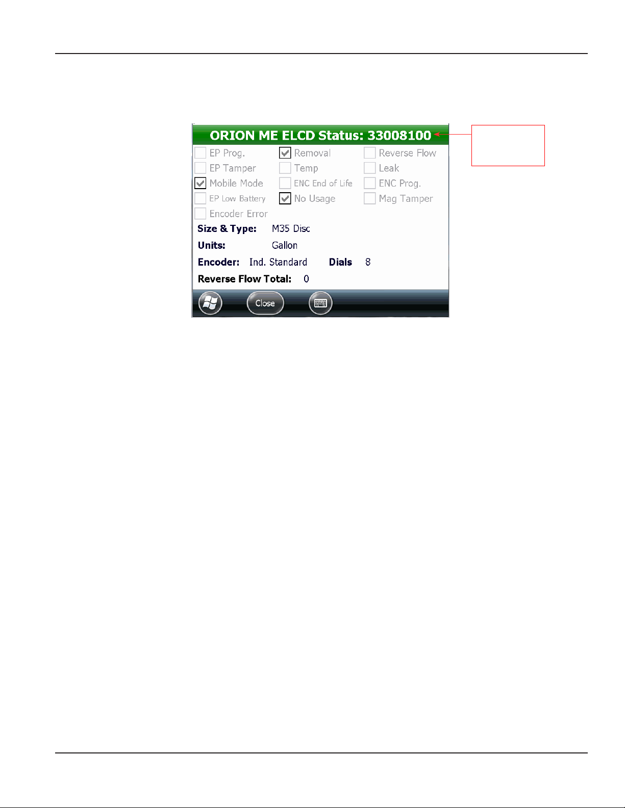
ENC Extended Status
Figure 27: Extended Status - ADE
The status indicators described below apply for an ORION Migratable or Fixed Network (in mobile mode) endpoint when
connected to an ADE encoder (ENC).
Status Indicator Description
Mobile Mode Endpoint is communicating in mobile transmission mode.
IR Programmed Endpoint has been reprogrammed via IR.
Low Battery Endpoint is reporting a low battery condition.
Tamper Endpoint is reporting a tamper condition. This condition occurs when the wire between the register
and the endpoint is cut or shorted, or the encoder is not connected.
Encoder Error Device error reported by the endpoint when the encoder exhibits a temporary or permanent failure
to extract the current reading.
No Usage Endpoint is reporting a no usage condition. This condition occurs when there is no water flow
registered over a 30-day time frame.
Leak Endpoint is reporting a potential condition when there is continuous usage over a 24-hour time
period without a non-usage period of about 2 hours.
Reverse Flow Encoder is reporting a reverse flow condition to the endpoint.
Encoder Information Description
Size & Type The size and type of the meter for which the encoder was programmed. Tap the button to change
the meter size and type. See "IR Programming Meter Size, Type and Units of Measure (RTR, ADE)"
onpage28 for more information.
Units The units of measure as defined by the encoder: cubic meters, cubic feet, gallons, imperial gallons or
liters. Tap the button to change the units. See "IR Programming Meter Size, Type and Units of Measure
(RTR, ADE)" onpage28 for more information.
Encoder The encoder protocol.
Dials The encoder dial resolution (4-, 5- or 6-dials) as reported from the encoder.
OTE:N Refer to the ORION Migratable Endpoint product data sheet, available at www.badgermeter.com, for
complete information.
Page 25 April 2014 ORION® Endpoint Utility for Trimble® Ranger 3
Page 26

ORION IR PROGRAMMING
High Resolution (HR) E LCD Extended Status
Figure 28: Extended Status - HR-E LCD
The status indicators described below apply for an ORION Migratable (or Fixed Network in mobile mode) endpoint when
connected to an HR-E LCD encoder.
Status Indicator Description
EP Prog Endpoint is reporting that it has been reprogrammed via IR.
EP Tamper Endpoint is reporting a tamper condition. This condition occurs when the wire between the
encoder and the endpoint is cut or shorted, or the encoder is not connected.
Mobile Mode Endpoint is communicating in mobile transmission mode.
EP Low Battery Endpoint is reporting a low battery condition.
Encoder Error Encoder is reporting a device error to the endpoint.
Removal Encoder is reporting an encoder removal condition to the endpoint.
Temp Encoder is reporting to the endpoint that it senses temperatures outside the specified range.
ENC End of Life Encoder is reporting to the endpoint that the encoder battery life indicator has been activated.
No Usage Encoder is reporting a no usage condition to the endpoint.
Reverse Flow Encoder is reporting a reverse flow condition to the endpoint.
Leak Encoder is reporting a potential leak condition to the endpoint.
ENC Prog Encoder is reporting to the endpoint that the encoder has been reprogrammed via IR.
Mag Tamper Encoder is reporting a magnetic tamper condition to the endpoint.
Encoder Information Description
Size & Type The size and type of the meter for which the encoder was programmed.
Units The units of measure as defined by the encoder: cubic meters, cubic feet, gallons, imperial gallons
or liters.
Encoder The encoder protocol.
Dials Encoder dial resolution (8) as reported from the encoder.
Reverse Flow Total The total reverse flow units measured by the encoder.
OTE:N Refer to the HR-E LCD Encoder Installation and Programming manual, available at www.badgermeter.com, for a detailed
list of encoder status indicators.
Page 26 April 2014ORION® Endpoint Utility for Trimble® Ranger 3
Page 27

ORION IR PROGRAMMING
High Resolution (HR) E-Series Extended Status
Figure 29: Extended Status - HR E-Series
The status indicators described below apply for an ORION Migratable (or Fixed Network in mobile mode) endpoint when
connected to an HR E-Series meter.
Status Indicator Description
EP Prog Endpoint is reporting that it has been reprogrammed via IR.
EP Tamper Endpoint is reporting a tamper condition. This condition occurs when the wire between the
E-Series meter and the endpoint is cut or shorted, or the encoder is not connected.
Mobile Mode Endpoint is communicating in mobile transmission mode.
EP Low Battery Endpoint is reporting a low battery condition.
Encoder Error E-Series meter is reporting a device error to the endpoint.
Empty Pipe E-Series meter is reporting a no flow condition in the pipe.
Low Temp E-Series meter indicates the low temperature limits have been exceeded.
ENC End of Life E-Series meter is reporting to the endpoint that the encoder battery life indicator has been
activated.
No Usage E-Series meter is reporting a no usage condition to the endpoint.
Reverse Flow E-Series meter is reporting a reverse flow condition to the endpoint.
Leak E-Series meter is reporting a potential leak condition to the endpoint.
Sensor Error Endpoint is reporting a sensor error or meter alarm other than empty pipe or low temp.
Encoder Information Description
Size & Type The size and type for which the E-Series meter was programmed.
Units The units of measure as defined by the E-Series meter: cubic meters, cubic feet, gallons,
imperial gallons or liters.
Encoder The encoder protocol.
Dials Encoder dial resolution (8) as reported from the E-Series meter.
Reverse Flow Total The total reverse flow units measured by the E-Series meter.
OTE:N Refer to the E-Series Installation and Programming manuals, available at www.badgermeter.com, for a detailed list of
encoder status indicators.
Page 27 April 2014 ORION® Endpoint Utility for Trimble® Ranger 3
Page 28

ORION IR PROGRAMMING
IR Programming Meter Size, Type and Units of Measure (RTR, ADE)
To program the meter type and size for an RTR or ADE encoder, follow these steps.
1. Tap the meter Size & Type button on the Extended Status screen.
2. Scroll through list (Figure 30) and tap to select the appropriate meter type and size .
Result: The Extended Status screen displays with the selected meter type and size (Figure 32). The new value is highlighted
to indicate it is not yet programmed.
Figure 30: Meter size & type
3. Tap the Units button.
4. Scroll through list (Figure 31) and tap to select the appropriate unit of measure.
Result: The Extended Status screen displays and highlights the selected units of measure (Figure 32).
5. Align the optical head of the IR cable with the endpoint IR LED port.
6. Tap the Program button on the Extended Status screen.
Result: The endpoint connected to the RTR is programmed with the new meter type, size and units as shown in Figure 33.
The new values are no longer highlighted to indicate the values are programmed.
Figure 31: Meter unit of measure
Figure 32: Meter type and size
Page 28 April 2014ORION® Endpoint Utility for Trimble® Ranger 3
Figure 33: Meter type and size programmed
Page 29

ORION IR PROGRAMMING
Advanced IR Programming
OTE:N Before beginning, make sure the IR programming cable is connected and the IR COM port is set correctly. See
"Hardware Settings" onpage63 for additional information.
After performing an IR read of an ORION Migratable endpoint, tap the Advanced button to access more information
and commands.
Use the Advanced button to see the endpoint firmware version, date/time, GPS location and battery status, and/or to request
a Flow Rate Study.
OTE:N The functionality available on the Advanced IR screen is also available on the ORION Quick Read - Single screen.
Figure 34: Advanced button on IR Programming screen
Advanced Screen Fields and Buttons
Firmware Displays the firmware version of the selected endpoint. Read only field
Endpoint Type Designates the reading technology compatible with the endpoint. Read only field
Set GPS Location Tap to store the latitude/longitude settings for the endpoint if a GPS antenna is
present. Populates automatically if the handheld has an onboard GPS or can be
entered manually.
Set Date/Time Tap to set the endpoint date/time using the handheld date/time. Programmable
Get Battery Status Tap to see the number of days left on the endpoint battery. Programmable
Flow Rate Study Displays the results when a flow rate study is requested. The field to the right of
the Start, Get, Save buttons displays the results.
• Start Tap to start a 7-day flow rate study. Programmable
• Get Tap to get the results from the flow rate study. Programmable
• Save Tap to save the flow rate study results. A screen displays showing where the file
is saved on the handheld.
Figure 35: Advanced screen
Programmable
Display field
Programmable
Page 29 April 2014 ORION® Endpoint Utility for Trimble® Ranger 3
Page 30

ORION IR PROGRAMMING
Setting GPS Location Manually
1. Tap the Set GPS Location button on the Advanced screen.
2. Check the Manual Entry box.
3. Tap in the Lat eld and use the handheld keypad or the onscreen keyboard to type the latitude. Tap in the Long eld
and use the handheld keypad or the onscreen keyboard to type the longitude. Make sure to add the decimal points
and a minus sign, if applicable.
OTE:N The minus sign/dash and the decimal point on the handheld numeric keypad are on the last row of blue
keys as shown in Figure 37.
4. With the IR cable connected to the handheld, align the optical head with the endpoint IR LED port and tap Program.
Result: The GPS location is programmed and displays next to the Set GPS Location button on the Advanced screen as
shown in Figure 38.
Figure 36: GPS manual entry
Figure 38: Endpoint GPS data programmed
Figure 37: Minus sign/dash (left) and decimal point (right)
Page 30 April 2014ORION® Endpoint Utility for Trimble® Ranger 3
Page 31

ORION IR PROGRAMMING
Set Date and Time
To synchronize the endpoint date and time to the date and time of the handheld, align the optical head with the endpoint
IR LED port and tap the Set Date / Time button on the Advanced screen. The synchronized date and time display next to
the button.
Get Battery Status
1. Align the optical head of the IR cable with the
endpoint IR LED port and tap Get Battery Status.
Result: The estimated number of remaining days
of endpoint battery life displays in the eld next to
the button.
2. Tap Back to return to the previous screen.
Figure 39: Endpoint battery status
Starting a Flow Rate Study
A flow rate study is a week-long study that can be performed on a Migratable (or Fixed Network in mobile mode) endpoint to
report high, low and average flow rates. The results can be saved for use in the reading data management software.
1. With the IR cable connected to the handheld, align
the optical head with the endpoint IR LED port and
tap Start.
Result: A message conrms the successful start of
the ow rate study. The study continues for one week
from the start time and date.
2. Tap Back to return to the previous screen.
Figure 40: Flow rate study
Getting Flow Rate Study Results
1. At the end of a week-long ow rate study, align the optical head of the IR cable with the endpoint IR LED port
tap Get.
Result: The data from the Flow Rate Study lls in the eld next to the Start, Get and Save buttons.
2. Tap Save to create a le of the data for use in the reading data management software.
Result: A screen displays showing the location of the saved le on the handheld.
3. Tap the Back button to return to the previous screen.
Page 31 April 2014 ORION® Endpoint Utility for Trimble® Ranger 3
Page 32

ORION IR PROGRAMMING
IR Programming an ORION Migratable Gas Endpoint
OTE:N Before beginning, make sure the IR programming cable is connected and the IR COM port is set correctly. See
"Hardware Settings" onpage63 for additional information.
OTE:N To see a complete list of the buttons and fields on the IR Programming screen for an ORION Migratable endpoint, see
"ORION Migratable Endpoint IR" onpage17.
1. From the ORION Endpoint Utility menu, tap ORION
IR Programming.
2. Align the optical head of the IR cable with the gas
endpoint IR LED port. Then tap Read.
Result: The IR Programming screen opens and the bar
at the top of the screen displays the gas endpoint type.
For gas endpoints that have not previously been
programmed, the Select Gas Drive Circle screen
opens rst. If that happens, skip to Step 4.
3. To view/change the drive circle, tap Change DC.
Result: The Select Gas Drive Circle screen is displayed.
4. Make any necessary changes to the Drive Circle.
• Use the selections in the top half of the screen
to filter the list on the bottom by choosing
Integral or Remote, and choosing the Units,
Dials and Res (resolution).
• Or just scroll through the list to find the drive
circle for the endpoint.
5. Tap to select the correct drive circle for the
gas endpoint.
Figure 41: ORION Migratable IR screen with read
Figure 42: Gas Drive Circle screen
Page 32 April 2014ORION® Endpoint Utility for Trimble® Ranger 3
Page 33

ORION IR PROGRAMMING
6. Tap in the Pressure eld. Then use the keypad to enter the correct pressure factor, if necessary.
7. Tap Direction. On the Select Meter Direction screen, tap to select Clockwise or Counter Clockwise for the drive gear.
Figure 43: Change gas pressure factor
Figure 44: Select drive gear direction
OTE:N For a list of meters and the rotation direction of the drive gear, see "Gas Meter Drive Rotation" onpage76 in
the Appendix.
8. Tap the Select button on the Select Gas Drive Circle screen to store the drive circle information you selected.
Result: The IR Programming screen displays.
If you made changes to the drive circle, the field is highlighted as shown in Figure 45.
Figure 45: Before programming
Figure 46: After programming
9. Align the optical head of the IR cable with the gas endpoint IR LED port and tap Program.
Result: The gas endpoint is programmed and the eld is no longer highlighted.
OTE:N With an ORION Migratable gas endpoint, you can also access the Drive Circle information via the
Ext. Status button.
Page 33 April 2014 ORION® Endpoint Utility for Trimble® Ranger 3
Page 34

ORION IR PROGRAMMING
ORION Classic Endpoint IR
Use the ORION IR Programming function to read ORION Classic water and gas endpoints, and to start, stop and pause an
endpoint. The ORION IR Programming function is also used to program an endpoint following a tamper repair or retrofit
installation (RTR water installations only).
Figure 47: IR Programming screen for ORION Classic endpoint
OTE:N Prior to performing any of the ORION Classic endpoint IR functions, connect the IR programming cable and an
ORION Classic mobile receiver (if necessary) to the handheld, and make sure the appropriate COM ports are set. See
"Glossary" onpage70 if you need help.
ORION Classic Endpoint IR Buttons
Read Read the endpoint using the IR programming cable.
Program /
Force Read
Stop Stop the endpoint from sending a transmission. Stopped endpoints must be re-programmed to begin
Pause Pause the endpoint transmission temporarily until a unit of water or gas is registered. (Common practice of
Start Start the endpoint radio transmission.
HPwr Force a brief high powered signal from the endpoint to an ORION Classic gateway receiver.
Listen Switches to RF (radio frequency) to "hear" if the endpoint is active.
ORION Classic Endpoint IR Buttons - Gas Endpoint Only
Drive Circle? Displays after initial read for ORION Classic gas endpoints only. Provides access to a read-only screen
Change DC Displays after initial read for gas endpoints only. Used to select the gas drive circle information.
ORION Classic Endpoint IR Fields
Serial # Displays the serial number of the ORION CE endpoint.
Reading Used to view the current endpoint reading value. For an RTR, it is used in conjunction with the Program
Status Displays the endpoint status which provides information regarding the programming and configuration of
Radio Used to view the endpoint radio transmission mode.
When used with an RTR encoder, Program is used to set the endpoint odometer value following a tamper
repair. When used with an ADE encoder, Force Read is used to view the real-time encoder odometer value.
transmitting again.
seasonal users.)
displaying the possible drive circles for the gas endpoint.
button to reprogram the odometer value after a tamper repair.
the endpoint. See "Status Codes" onpage75 for a list of status codes.
Page 34 April 2014ORION® Endpoint Utility for Trimble® Ranger 3
Page 35

ORION IR PROGRAMMING
Start, Pause, Stop - Radio Modes
All ORION Classic endpoints are programmed at the factory to begin sending meter readings as soon as the register senses
flow through the meter. As a result, ORION Classic endpoints can be installed on meters without having to manually start the
endpoint. When usage is registered on the meter, the endpoint sends a signal every four seconds.
The Stop button is used to stop an endpoint from sending a signal, regardless of
the usage registered from the meter. Align the optical head on the IR cable with
the endpoint IR LED port and tap Stop. The Start button must be used to turn the
endpoint on again.
The Pause button is used to pause the radio signal temporarily. Align the optical
head on the IR cable with the endpoint IR LED port and tap Pause. The endpoint
begins transmitting again when usage is registered from the meter.
The Start button is used to start an endpoint after it is stopped or before usage is registered. Align the optical head on the IR
cable with the endpoint IR LED port and tap Start.
OTE:N Stopped radios must be restarted using the Start function (above) and will not automatically restart when usage
is registered from the meter. When used with an RTR, the odometer value must also be programmed to reflect the
current registration reading. See "IR Programming an ORION Classic Endpoint (RTR)" onpage36 for more information.
When used with an ADE, the odometer value is automatically updated within the hour.
Figure 48: Radio modes
Page 35 April 2014 ORION® Endpoint Utility for Trimble® Ranger 3
Page 36

ORION IR PROGRAMMING
IR Programming an ORION Classic Endpoint (RTR)
1. Align the optical head of the IR cable with the
endpoint IR LED port and tap Read on the IR
Programming screen.
2. Double-tap the reading in the Reading eld.
Result: The reading in the eld is highlighted
(Figure 49).
Figure 49: Reading field highlighted
3. Using the handheld keypad, enter the RTR odometer value in the Reading eld.
See "Reading the Odometer" onpage20 for more information.
Result: The inside of the Reading box is highlighted (Figure 50) to indicate a new value is entered in the field but not
yet programmed.
OTE:N Leading zeros are not required, however it may be helpful to enter leading zeros as visual confirmation. Only
seven digits can be entered when programming an endpoint, regardless of the meter size.
4. Align the optical head of the IR cable with the endpoint IR LED port and tap Program.
Result: The endpoint is programmed with the new value and the reading box is no longer highlighted. See Figure 51.
Figure 50: New reading value entered
OTE:N When programming an endpoint after clearing a tamper, verify that the programming and wire splicing were
successful. Select ORION Quick Read - Single from the Menu to perform a Quick Read on the endpoint. If the
endpoint still reports “Tamper” in the Status eld, check the wire splices, repair as necessary and then repeat the
programming procedure above.
Figure 51: New reading value programmed
Page 36 April 2014ORION® Endpoint Utility for Trimble® Ranger 3
Page 37

ORION IR PROGRAMMING
IR Force Read (ADE)
When an ORION Classic endpoint connected to an ADE encoder is read, the Force Read button displays instead of the
Program button on the IR Programming screen. Force Read is used to view the real-time encoder odometer value and to
verify a successful tamper repair.
1. Align the optical head of the IR cable with the
ORION Classic endpoint IR LED port.
2. On the ORION IR Programming screen, tap Read to
read the endpoint.
3. Tap Force Read.
Result: The endpoint transmission starts and the
reading value updates to reect the current encoder
odometer value.
Figure 52: Force Read on ADE
Listen
OTE:N Prior to using the Listen function, make sure the handheld has a built in ORION Classic receiver or an external mobile
receiver is connected and the appropriate COM port is set. See "Glossary" onpage70 if you need help.
Tap Listen to activate radio frequency (RF) and display the ORION Quick Read - Single screen for the selected endpoint.
For additional information, see "ORION Quick Read-Single" onpage46.
Page 37 April 2014 ORION® Endpoint Utility for Trimble® Ranger 3
Page 38

ORION IR PROGRAMMING
IR Programming an ORION Classic Gas Endpoint
OTE:N Before beginning, make sure the IR programming cable is connected and the COM port is set correctly. See "Hardware
Settings" onpage63 for additional information.
1. From the ORION Endpoint Utility menu, tap ORION IR Programming.
2. Align the optical head of the IR cable with the gas endpoint IR LED port. Then tap Read.
Result: The Select Gas Drive Circle screen is displayed automatically.
Figure 53: IR programming screen with Read
3. To change the pressure factor, tap in the Pressure
eld. Use the keypad to change the pressure factor,
if necessary.
4. Select the Drive Circle for the gas endpoint.
• Use the selections in the top half of the screen
to filter the list on the bottom by choosing
Integral or Remote, and choosing the Units,
Dials and Res (resolution).
• Or just scroll through the list to find the drive
circle for the endpoint.
5. Tap the Select button to store the drive circle.
6. Result: The IR Programming screen is displayed with the
selected drive circle displayed.
Figure 54: Select Gas Drive Circle screen
Figure 55: Gas pressure factor
Figure 56: Gas drive circle
Page 38 April 2014ORION® Endpoint Utility for Trimble® Ranger 3
Page 39

7. Align the optical head of the IR cable with the gas
endpoint IR LED port. Then tap Program.
Result: The gas endpoint is programmed.
Possible Drive Circles
The Drive Circle? button provides access to a list of possible
drive circles.
After performing an initial read of the endpoint, tap the Drive
Circle? button to see the list as shown in Figure 58. This is a
read only screen to help select the correct drive circle.
ORION IR PROGRAMMING
Figure 57: Endpoint programmed
Tap the Cancel button to return to the IR Programming screen.
Figure 58: Gas drive circles
Page 39 April 2014 ORION® Endpoint Utility for Trimble® Ranger 3
Page 40

ORION IR PROGRAMMING
Reprogramming a Gas Drive Circle
To reprogram an ORION Classic endpoint and change the gas drive circle after it has been programmed, follow these steps.
1. From the ORION Endpoint Utility menu, tap ORION IR Programming.
2. Align the optical head of the IR cable with the ORION Classic gas endpoint IR LED port. Then tap Read.
Result: The Select Gas Drive Circle screen is displayed automatically.
Figure 59: ORION Classic IR Programming screen
3. Tap the Cancel button to return to the IR
Programming screen.
4. Tap the Change DC button.
Figure 60: Tap Cancel
Figure 61: Tap Change DC
Page 40 April 2014ORION® Endpoint Utility for Trimble® Ranger 3
Page 41

ORION IR PROGRAMMING
Result: The Select Gas Drive Circle screen is
displayed again.
5. Select the drive circle settings, then tap the
Select button.
Figure 62: Select new gas drive circle
6. The IR Programming screen is displayed with the selected drive circle information highlighted.
7. Align the optical head of the IR cable with the endpoint IR LED port and tap Program.
Figure 63: New drive circle selected
Figure 64: New drive circle programmed
Result: The gas endpoint is reprogrammed with the new drive circle information which is no longer highlighted.
Page 41 April 2014 ORION® Endpoint Utility for Trimble® Ranger 3
Page 42

ORION QUICK READ
ORION QUICK READ
The ORION Quick Read functions are used to listen for ORION Migratable and Classic endpoints within range using radio
frequency (RF). ORION Quick Read - All is used to listen to all endpoints within range. ORION Quick Read - Single is used to
listen for a specific endpoint within range.
OTE:N Cellular endpoints cannot be read via RF, therefore, Quick Read functions do not apply to ORION Cellular endpoints.
Figure 65: ORION Quick Read - All
Quick Read is used to perform a number of functions on ORION Migratable and Classic endpoints and touch modules. The
most common uses of Quick Read include:
• Reading an endpoint or touch module (outside of the route reading process) when testing or troubleshooting at a
customer site.
• Reading one or more endpoints or touch modules prior to installation, to verify the endpoints or modules are
working correctly.
• Clearing a tamper and reprogramming the odometer (RTR only) after the wire repair.
• Testing a newly installed endpoint.
• Performing meter testing at the meter shop.
• Getting a final reading from a meter.
OTE:N Make sure the handheld is configured for the type of endpoint you want to read. See "Glossary" onpage70 for more
information.
When finished using the ORION Quick Read functions, tap the Menu button to choose another ORION Endpoint Utility option
or exit the software.
Page 42 April 2014ORION® Endpoint Utility for Trimble® Ranger 3
Page 43
ORION QUICK READ
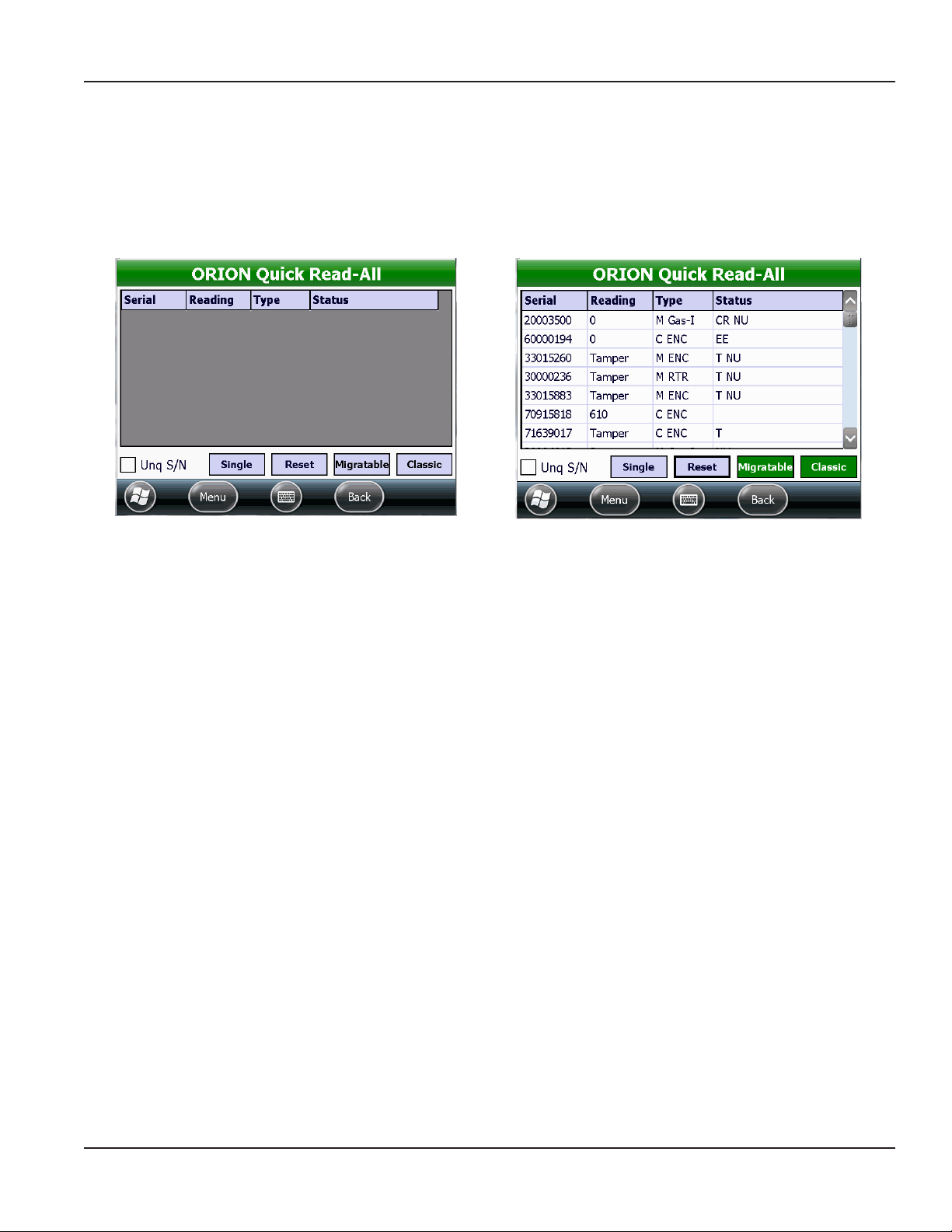
ORION Quick Read-All
The ORION Quick Read-All screen displays readings for all ORION Migratable and Classic endpoints in range, up to 50 readings.
One endpoint may display several readings during a Quick Read.
OTE:N Make sure the handheld is configured for the type of endpoint you want to read. See "Glossary" onpage70 for more
information.
Figure 66: Quick Read-All screen without readings
Fields Quick Read-All
Serial Displays the endpoint serial number.
Reading Displays a reading for the corresponding endpoint serial number.
Type Displays the encoder type.
Status Displays any potential exception issues such as a tamper (T) or no usage (NU). If no exception is noted, the
Status field is blank.
OTE:N For a list of status codes and their descriptions, see "Status Codes" onpage75.
Buttons Quick Read-All
Single/List Displays the quick read of a single endpoint or a quick read list of all endpoints. Tap Single or List to toggle
between the individual endpoint view and list view.
Reset Clears the current screen. Tap Migratable and/or Classic to begin reading again.
Unq S/N Displays each unique endpoint serial number once if the box is checked.
Save Captures a Quick Read session and saves it to a file on the handheld.
OTE:N These files are not included with the route reading files.
Migratable Tap Migratable once to start reading ORION Migratable water and gas endpoints. Tap again to stop the
Quick Read.
Classic Tap Classic once to start reading ORION Classic water and gas endpoints. Tap again to stop the Quick Read.
Figure 67: With ORION endpoint readings
Page 43 April 2014 ORION® Endpoint Utility for Trimble® Ranger 3
Page 44

ORION QUICK READ
Performing a Quick Read - All Endpoints
1. From the ORION Endpoint Utility menu, select ORION
QuickRead- All.
2. On the ORION Quick Read - All screen, tap
Migratable once and tap Classic once to listen for
all ORION Migratable and Classic water and gas
endpoints in range.
Result: All ORION Migratable and Classic endpoint
readings within range display as shown (Figure 68).
Notice both the Migratable and Classic buttons
are selected.
OTE:N To listen for only one endpoint type, tap the button for the endpoint type you want to display. For example, tap
Migratable to listen for ORION Migratable endpoints only.
Figure 68: Quick Read all endpoints
3. View the list of readings and statuses by scrolling up and down.
4. Tap Migratable again to stop the ORION Migratable endpoint Quick Read. Tap Classic again to stop the ORION
Classic endpoint Quick Read.
5. To save the readings, tap the Menu button to bring up the ORION Endpoint Utility menu (Figure 69).
6. Tap Save Reads.
Result: The Quick Read Data Saved screen opens, showing the location of the saved le. (Figure 70).
7. Tap Ok to close the Quick Read Data Saved screen and return to the ORION Quick Read-All screen.
Figure 69: Menu> Save Reads
Figure 70: Quick Read data saved on handheld
Page 44 April 2014ORION® Endpoint Utility for Trimble® Ranger 3
Page 45
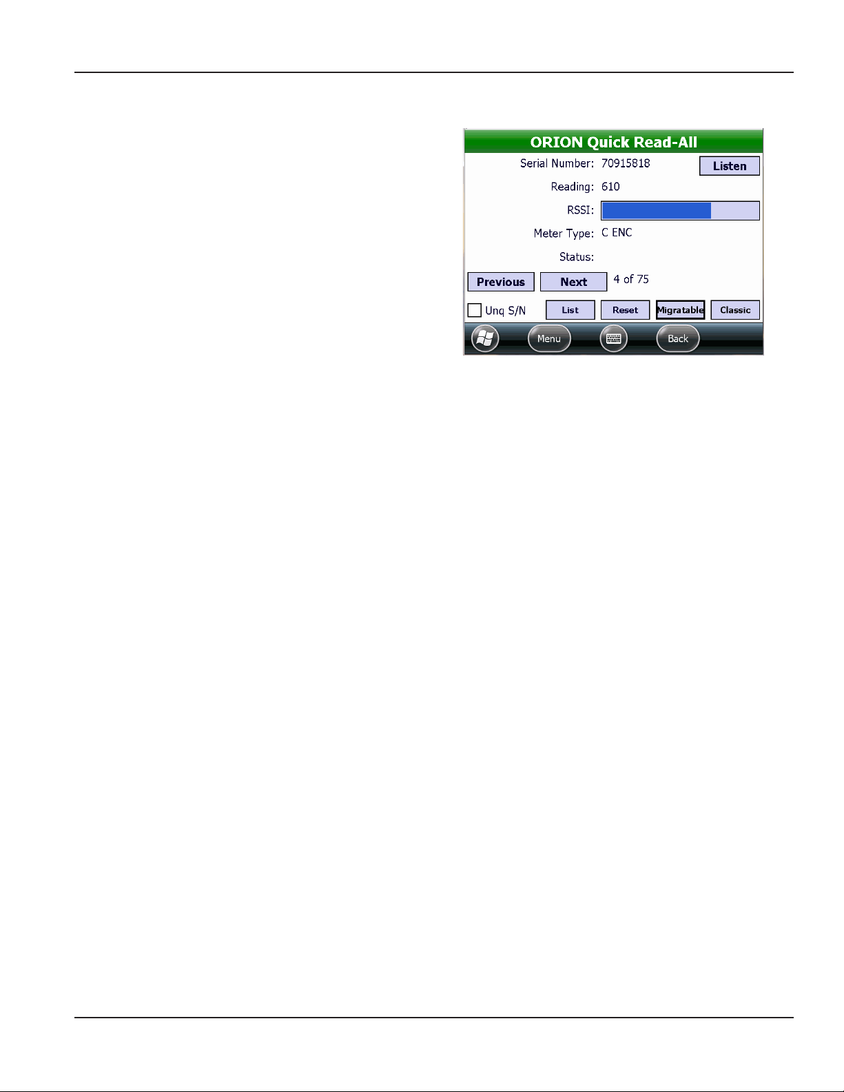
Single Reading View
1. On the ORION Quick Read - All screen, tap Single.
In Single view (Figure 71) you can see each endpoint
individually. RSSI, a visual indicator of received signal
strength between the endpoint and the handheld,
also displays.
2. Tap Listen to open the ORION Quick Read - Single
screen for the endpoint. For more information, see
"ORION Quick Read-Single" onpage46.
3. Tap Previous or Next to view another endpoint.
4. Tap List to return to the ORION Quick Read - All
list view.
ORION QUICK READ
Figure 71: Single endpoint view
Page 45 April 2014 ORION® Endpoint Utility for Trimble® Ranger 3
Page 46

ORION QUICK READ
ORION Quick Read-Single
The ORION Quick Read - Single screen is used to perform
a Quick Read on a single ORION Migratable or Classic
endpoint using radio frequency (RF).
Quick Read - Single Fields
S/N Type the serial number of the ORION endpoint in this field.
RSSI Received Signal Strength Indicator of the signal strength between the endpoint and the handheld.
∆T Displays the number of seconds that have lapsed between transmissions. This field continues to
update during the Quick Read.
Status Any status alert codes display in this field. See "Status Codes" onpage75 for a list of codes.
M/C Indicates the technology communicating with the handheld. In Figure 72, “M” and “C” are displayed
with a green background, indicating good communication between the ORION Migratable
transceiver (M), the ORION Classic receiver (C) and the handheld. If there is no communication
between the technology and the handheld, the indicator will have a red background.
Duration Displays the number of seconds since the Start button was tapped.
Tot. Count Displays the number of transmissions from the endpoint.
S/N Count Displays the number of readings currently showing on the screen.
ORION Quick Read - Single Buttons
Start/Stop Toggles to start and stop the Quick Read.
Reset Clears the current data, then continues the Quick Read.
More Displays the advanced functions for ORION Migratable endpoints only. See an example in Figure 73
on the next page. Tap MORE to access the Advanced screen, which is used to set the endpoint date
and time, start and get results of a flow rate study and get the battery status.
Figure 72: ORION Quick Read - Single without data
Page 46 April 2014ORION® Endpoint Utility for Trimble® Ranger 3
Page 47

ORION QUICK READ
Performing a Quick Read - Single Endpoint
1. On the ORION Quick Read - Single screen, tap in the
S/N eld and use the handheld keypad to enter the
serial number of an endpoint.
2. Tap Start.
Result: Readings from the endpoint ll in the elds of
the table and the More button becomes active.
Tap More to access more information and
additional commands.
Tap Reset to clear the screen and begin the
read again.
Tap Stop to stop the radio.
3. To read another endpoint, double tap in the S/N
eld to highlight the serial number. Then use the
handheld keypad to enter a new serial number.
Figure 73: ORION Quick Read - Single with data
Quick Read - More
Tap the More button on the Quick Read - Single screen to display the Advanced screen for ORION Migratable endpoints only
(Figure 74). The following information is available on the Advanced screen.
Get Extended Status Tap to display a screen with the endpoint extended status which includes meter size, model
type and units, as well as any status alerts. Tap the View button to display the Extended Status
screen. For more information about Extended Status, see "Extended Status" onpage23 in the
IR Programming section.
Get Firmware Version Tap to access and display the endpoint rmware version in the eld.
Get Date/Time Tap to set the endpoint date and time using the handheld date and time.
Get Location Tap to set the latitude/longitude settings for the endpoint if a GPS antenna is present. For more
information, see "Setting GPS Location Manually" onpage30 in the IR Programming section.
Flow Rate Study The field to the right of the Start, Get, Save buttons displays the flow study results.
• Start Tap to start a 7-day flow rate study.
• Get Tap to get the results from the flow rate study.
• Save Tap to save the flow rate study results.
Figure 74: Tap MORE to access the Advanced screen for an
ORION Migratable endpoint
Figure 75: ORION Migratable endpoint with data
Page 47 April 2014 ORION® Endpoint Utility for Trimble® Ranger 3
Page 48

ORION PROFILE EXTRACTION
ORION PROFILE EXTRACTION
The ORION Profile Extraction function is used to extract historical profile data from ORION Migratable (or Fixed Network in
mobile mode) endpoints and ORION Classic endpoints that support data profile. Select ORION Profile Extraction on the
ORION Endpoint Utility main screen.
Figure 76: ORION Profile Extraction on the ORION Endpoint Utility menu
The main ORION Profile Extraction screen includes two functions. Use the Extract New Profile function to get historical profile
data from an endpoint via IR or RF. After a profile is extracted, use the Transfer Profiles function to store the data file on a flash
drive or memory stick for viewing in the ORION Profile Viewer software.
Figure 77: ORION Profile Extraction menu
When finished using the ORION Profile Extraction function, tap the Menu button to choose another ORION Endpoint Utility
option or exit the software.
Page 48 April 2014ORION® Endpoint Utility for Trimble® Ranger 3
Page 49

Prole Extraction - IR
1. From the ORION Prole Extraction menu, select
Extract New Prole.
2. Tap the IR/RF box so IR displays (Figure 78).
3. With the IR cable connected to the handheld, align
the optical head with the endpoint IR LED port and
tap Initial Read.
Result: The endpoint serial number and type displays
as shown in Figure 79.
ORION PROFILE EXTRACTION
Figure 78: IR profile extraction
Figure 79: Select number of days
4. Change the encoder read resolution, if necessary.
• Tap the Read Res. button to see a list of test circles.
• Tap to select a test circle and the selection will automatically display on the screen.
5. Use the drop-down menu to select the number of days for the prole data extraction (Figure 79).
6. Tap the Get Prole button to extract the prole data. Make sure to align the optical head of the IR cable with the
endpoint IR LED port before to tap the button.
Result: A progress bar displays on the screen. The prole data is extracted for the number of days selected and displayed on
the screen (Figure 80).
Figure 80: Profile data extracted
Page 49 April 2014 ORION® Endpoint Utility for Trimble® Ranger 3
Page 50

ORION PROFILE EXTRACTION
7. Tap the Save button to save the historical prole
data.
Result: The le is saved to the handheld with the serial
number and the date and time of the save in the le
name. The Interval Data Saved conrmation screen
displays as shown in the example in Figure 81.
8. Tap Ok to close the screen and return to the Prole Extraction screen.
OTE:N For a complete list of the Profile Extraction screen fields and buttons and their definitions, see "Profile
Extraction Fields and Buttons" onpage52.
Figure 81: Profile data saved
Prole Extraction - RF
OTE:N RF profile extraction can be performed on ORION Migratable (or Fixed Network in mobile mode) endpoints only.
To access and extract profile data from an ORION endpoint using RF, follow these steps.
1. Tap the IR/RF box so RF displays.
2. Tap in the S/N eld and use the handheld keypad to
enter the serial number of the endpoint.
Result: Status messages display – one at a time. This
process takes several seconds.
• Waiting for Mobile Message
• Getting Mobile Configuration
• Getting Extended Status (ORION Migratable
endpoints only)
Figure 82: RF Profile - Waiting for Mobile Message
Page 50 April 2014ORION® Endpoint Utility for Trimble® Ranger 3
Page 51

ORION PROFILE EXTRACTION
Figure 83: Select number of days
Figure 84: Profile data extracted
3. Change the encoder read resolution, if necessary.
• Tap Read Res. to see a list of test circles.
• Tap to select a test circle and the selection will automatically display on the screen.
4. Use the drop-down menu to select the number of days for the prole data extraction.
5. Tap the Get Prole button to extract the prole data.
Result: A progress bar displays on the screen. When the extraction is complete, the prole data is extracted for the
number of days selected and displayed on the screen (Figure 84).
6. Tap Save to save the historical prole data.
Result: The le is saved to the handheld with the serial
number and the date and time of the save in the le
name. The Interval Data Saved conrmation screen
displays as shown in the example in Figure 85.
7. Tap Ok to close the screen and return to the ORION
Prole Extraction screen.
Figure 85: Profile data saved
OTE:N For a complete list of the ORION Profile Extraction screen fields and buttons and their definitions, see "Profile
Extraction Fields and Buttons" onpage52.
Page 51 April 2014 ORION® Endpoint Utility for Trimble® Ranger 3
Page 52

ORION PROFILE EXTRACTION
Profile Extraction Fields and Buttons
S/N Displays the serial number of the ORION Migratable endpoint.
IR / RF Extract profile data via IR or RF. Tap the box to select.
Days Drop-down menu used to select the number of days for the profile extraction. Available choices:
7, 14, 30, 60, All (90).
Read Res. Tap to see a list of test circles for the encoder.
Oldest Reading The date and time of the oldest reading in the extracted data.
Interval The reading interval at which the endpoint is set: 60 (every hour) or 15 (every quarter hour)
Quantity The number of interval reads extracted from the endpoint.
Status(es) Displays any potential issues that require attention. Example: tamper, no usage, etc.
Change Interval Tap to change the reading interval for the endpoint. A message asking for confirmation displays
before and after changing the interval. All currently stored profile data is erased when the interval
is changed.
Clear Endpoint Tap to erase the stored historical interval data for the endpoint.
Save Saves the extracted data on the handheld. The .csv file can be viewed with the ORION Profile
Viewer software.
A confirmation message displays to show where the file is saved on the handheld. The file location
path includes the endpoint serial number and the date and time.
Example: \Program Files\Badger Field Applications\Mobile Read.Net\ProfileExtraction\
LogFiles\30000264 20140205 115349.csv
Show Archived Tap to show previously transferred profile data files.
The chart below shows the number of readings collected for meters set at 60 minute (hourly) intervals and at 15 minute
(quarter hourly) intervals:
Available Prole Data
Extraction Intervals
7 days 168 reads (24 x 7) 672 (96 x 7)
14 days 336 reads (24 x 14) 1344 (96 x 14)
30 days 720 reads (24 x 30) 2160 (96 x 22.5)
60 days 1440 reads (24 x 60) 2160 (96 x 22.5)
All/ 90 days 2160 reads (24 x 90) 2160 reads (96 x 22.5)
Hourly Reads:
1 Read per Hour
24 Reads per Day
15 Minute Reads:
4 Reads per Hour
96 Reads per Day
OTE:N The ORION Migratable (or Fixed Network in mobile mode) water endpoint is capable of storing up to 90 days of
hourly interval data, or 2160 hourly reads. If the account is set up to read every 15 minutes – 4 readings per hour –
the data extracted reflects four (4) readings per hour and reaches the maximum 2160 reads in 22.5 days
(90 days / 4 = 22.5 days).
Page 52 April 2014ORION® Endpoint Utility for Trimble® Ranger 3
Page 53

Transfer Proles
Figure 86: Transfer profiles
To transfer an extracted data file, saved on the handheld, to a memory stick, follow these steps.
ORION PROFILE EXTRACTION
1. From the ORION Prole Extraction menu, select
Transfer Profiles.
Result: Saved (archived) Transfer Profiles are displayed.
2. Tap to select a le to transfer. If you want to transfer
all the les, use the Select All button.
Result: The Transfer button becomes active.
3. Insert a memory stick into the USB port on the
handheld. Then tap Transfer.
Result: The file(s) are transferred to the memory stick.
When the transfer is complete, the selected file(s) are
removed from the screen and the Transfer button
becomes inactive.
OTE:N Transferred files are still available. Tap Show
Archived to see the transferred files.
Number of
selected files
Figure 87: Select file to transfer
Total number
of files
Page 53 April 2014 ORION® Endpoint Utility for Trimble® Ranger 3
Page 54
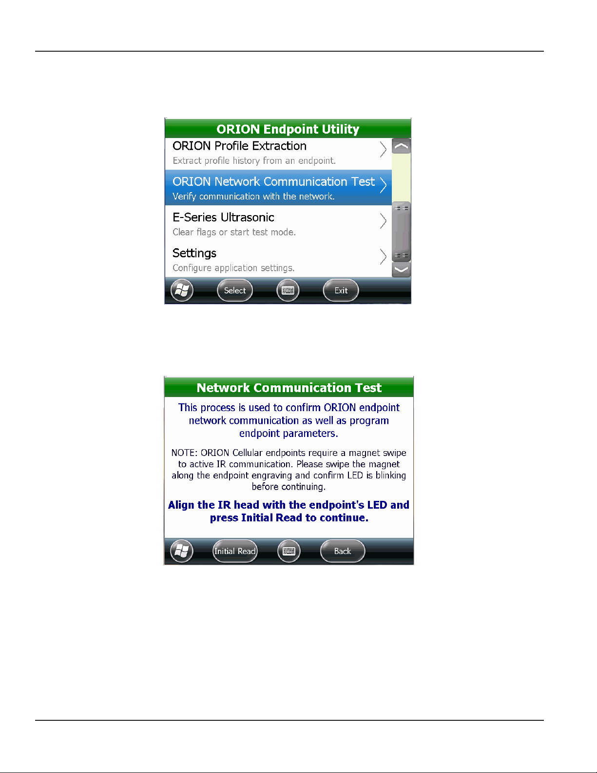
ORION NETWORK COMMUNICATION TEST
ORION NETWORK COMMUNICATION TEST
The ORION Network Communication Test is used to ORION endpoint communication with the network. Select ORION
Network Communication Test on the ORION Endpoint Utility main screen.
Figure 88: ORION Network Communication Test on the ORION Endpoint Utility menu
ORION Network Communication Test can be used with ORION Cellular, Fixed Network and Migratable endpoints to start the
endpoint radio, confirm endpoint communication with an ORION Fixed Network gateway or BEACON software, and program
endpoint parameters. The network communication test can also be done as part of an endpoint/meter installation.
Figure 89: Network Communication Test
When finished using the Network Communication Test function, tap the Menu button to choose another ORION Endpoint
Utility option or exit the software.
Page 54 April 2014ORION® Endpoint Utility for Trimble® Ranger 3
Page 55

Network Communication Test - ORION Cellular Endpoint
1. Select ORION Network Communication Test on the
ORION Endpoint Utility menu.
2. Align the IR optical head with the endpoint IR LED
port.
OTE:N For ORION Cellular endpoints, swipe with
the magnet to place the endpoint in active
IR mode.
3. Tap Initial Read.
Result: Endpoint type, serial number and reading is displayed.
4. (Optional) Tap Capture GPS if you want to enter a GPS location.
Result: The Capture GPS Location screen appears.
ORION NETWORK COMMUNICATION TEST
Figure 90: Initial Read to start test
• If the handheld has built-in GPS, the latitude/longitude (Lat/Long) values fill in automatically. Tap the Lock In
button to lock in the lat/long values.
• To enter lat/long manually, tap to select the Manual Entry box. Use the onscreen keyboard or the handheld
keypad to enter the values.
OTE:N The minus sign and the decimal point are on the handheld keypad in the last row of blue keys.
• Align the optical head of the IR cable with the endpoint IR LED port and tap Program to store the lat/long and
return to the previous screen.
Page 55 April 2014 ORION® Endpoint Utility for Trimble® Ranger 3
Page 56

ORION NETWORK COMMUNICATION TEST
5. Place the endpoint into position.
OTE:N Put the endpoint into its final physical
location. For example, with a pit lid
installation, mount the endpoint according
to the pit lid installation instructions before
proceeding.
6. Align the optical head of the IR cable with the
endpoint IR LED port and tap IR GO.
Result: The software goes through a series of steps to
complete the Ping.
“Ping completed” displays when the communication
test is complete.
7. Tap Finish to return to the Network Communication
Test main screen.
Figure 91: Place the endpoint
Figure 92: Communication test complete
Page 56 April 2014ORION® Endpoint Utility for Trimble® Ranger 3
Page 57

ORION NETWORK COMMUNICATION TEST
Network Communication Test - ORION Fixed Network and Migratable Endpoints
Access the Network Communication Test screen from the ORION Endpoint Utility menu. See page 10 if you need help.
1. Align the optical head of the IR cable with the
endpoint IR LED port and tap Initial Read.
Result: An initial read of the endpoint is performed and
Test 1 of 2 displays as shown in Figure 93.
2. (Optional) Tap Capture GPS if you want to enter a
GPS location.
Result: The Capture GPS Location screen appears.
Figure 93: Initial read
• If the handheld has built-in GPS, the latitude/longitude (lat/long) values fill in automatically. Tap the Lock In
button to lock in the lat/long values.
• To enter lat/long manually, tap to select the Manual Entry box. Use the onscreen keyboard or the handheld
keypad to enter the values.
OTE:N The minus sign and the decimal point on the handheld keypad are on the last row of blue keys.
Figure 94: Acquiring GPS
• Align the optical head of the IR cable with the endpoint IR LED port and tap Program to store the lat/long and
return to the previous screen.
Figure 95: GPS acquired and locked in
Page 57 April 2014 ORION® Endpoint Utility for Trimble® Ranger 3
Page 58

ORION NETWORK COMMUNICATION TEST
3. Check the “Listen for Gateway” box on the screen for xed network applications.
4. To view existing endpoint settings or set new ones, tap Set Endpoint Properties.
Result: A screen displays with the meter type, size and unit of measure as shown in Figure 97.
Typically, the properties do not need to be changed. However, if an endpoint with an RTR or ENC encoder is being
installed on a dierent meter or a gas meter, you can tap Size & Type and Units to change the properties. Align
the optical head of the IR cable with the endpoint IR LED port and tap the Program button to set the new
endpoint properties.
Tap Close if you do not wish to make any changes.
Figure 96: Set Endpoint Properties
Figure 97: Set endpoint properties
5. Align the optical head of the IR cable with the endpoint IR LED port and tap IR START.
Result: The Network Communication Test 2 of 2 screen displays.
6. If it is being installed, place the endpoint into position.
OTE:N Put the endpoint into its final physical location. For example, with a pit lid installation, mount the endpoint
according to the pit lid installation instructions before proceeding.
7. Wait for radio (RF) communication (Figure 98) from the endpoint. When RF communication is made, the RF GO button
becomes active. Tap RF GO (Figure 99).
Figure 98: Waiting for radio communication
Page 58 April 2014ORION® Endpoint Utility for Trimble® Ranger 3
Figure 99: RF GO
Page 59

ORION NETWORK COMMUNICATION TEST
Result: Messages display while the endpoint attempts to make radio contact with any gateway(s).
The serial numbers are listed for the gateways that acknowledge the endpoint signal.
Endpoints with Firmware Lower Than x.12: The endpoint attempts to communicate with gateways in range. The
serial numbers for the gateways from which the endpoint has received acknowledgement are listed.
Endpoints with Firmware x.12 or Higher: The endpoint makes multiple attempts to communicate with gateways
in range. The serial numbers for the gateways from which the endpoint has received acknowledgement are listed.
Color and percentage indicators are also used. Completed communications are shown in green, yellow or red
as described in the table below, with green indicating gateways that have the highest percentage of completed
communications. An example of the results is shown in Figure 101.
Color Successful Communication Attempts
Green 83…100% 5 of 6…6 of 6
Yellow 50…66% 3 of 6…4 of 6
Red 17…33% 1 of 6…2 of 6
Figure 100: Response with firmware x.12 or higher
Figure 101: Response with firmware lower than x.12
The ”Gateway Ping Complete“ message displays when all gateways are displayed.
8. Tap Finish to return to the Network Communication Test main screen.
OTE:N If the endpoint is unable to communicate with a gateway, a message displays ”Endpoint is unable to hear
any nearby gateways. Would you like to retry?“ Tap Retry. For additional help, contact Badger Meter
Technical Support.
Page 59 April 2014 ORION® Endpoint Utility for Trimble® Ranger 3
Page 60

ESERIES ULTRASONIC
ESERIES ULTRASONIC
The E-Series Ultrasonic function allows communication between the handheld and the E-Series Ultrasonic meter via the
meter IR port.
Figure 102: E-Series Ultrasonic on the ORION Endpoint Utility menu
Select E-Series Ultrasonic from the ORION Endpoint Utility menu to start test mode or clear flags.
Figure 103: E-Series Ultrasonic
Page 60 April 2014ORION® Endpoint Utility for Trimble® Ranger 3
Page 61

ESERIES ULTRASONIC
Start Test Mode Initiates the meter test mode. This option is used to increase the test sampling rate of the meter when
testing E-Series meters at ultra-low flow rates.
Refer to the E-Series Testing Considerations Application Brief, which can be found at
www.badgermeter.com, for operating instructions.
Clear Flags Clears any status indicators on the E-Series meter:
• Meter Alarm
• Reverse Flow
• Suspected Leak
• 30 Day No Usage
• End of Life (battery indicator)
OTE:N This function clears the status indicator(s) on the meter only. This function is typically used in
troubleshooting. The status indicator will display again if the condition reoccurs after
it is cleared.
1. With the IR cable connected to the handheld, align the optical head of the IR cable with the E-Series IR LED port.
2. Then tap the button for the function you desire.
When finished using the E-Series Ultrasonic functions, tap the Menu button to choose another ORION Endpoint Utility option
or exit the software.
Page 61 April 2014 ORION® Endpoint Utility for Trimble® Ranger 3
Page 62

SETTINGS
SETTINGS
The Settings function is used to configure settings for the handheld and any attached devices. Settings should be configured
before using the ORION Endpoint Utility functions.
Figure 104: Settings on the ORION Endpoint Utility menu
Select Settings from the ORION Endpoint Utility menu to configure any devices attached to the handheld, set logging
options and set the defaults used for profile extraction.
Figure 105: Settings screen
When finished using the Settings functions, tap the Menu button to choose another ORION Endpoint Utility option or exit
the software.
Page 62 April 2014ORION® Endpoint Utility for Trimble® Ranger 3
Page 63

SETTINGS
Hardware Settings
The Hardware Settings screen is used to view and change the communication (COM) ports for the handheld and add or
remove a device attached to the handheld. The Hardware Settings screen shows the following defaults, depending on the
type of handheld.
• Technology connected to the nine-pin serial port uses COM 1. The default shows the IR Head.
• The built-in GPS on the handheld uses COM 2. GPS does not display if the handheld does not have internal GPS.
• The internal technology on the handheld uses COM 7.
OTE:N For a complete list of valid COM ports, see "Valid COM Ports" onpage75 in the Appendix.
Figure 106: Hardware Settings screen
Recommended practice is to configure the settings on the handheld only for devices you are going to use.
Page 63 April 2014 ORION® Endpoint Utility for Trimble® Ranger 3
Page 64

SETTINGS
Add Device
Access Hardware Settings from Settings on the ORION Endpoint Utility menu.
1. On the Hardware Settings screen, tap Add Device.
Result: The Add Device screen opens.
2. Tap Type to see a list of device types to select
from. Then tap the device you want to add.
Result: The device you selected is displayed in the
Type eld. The example in Figure 107 shows the
ORION CE Receiver was selected.
3. Tap Port to set the COM port for the device
you added.
Result: The COM port you selected is displayed in the
Port eld. The example in Figure 107 shows COM 1
was selected.
4. Tap the Save button.
Result: The Hardware Settings screen opens showing
the device and COM port you added (Figure 108).
OTE:N See "Glossary" onpage70 for more information.
5. Tap Back to return to the Settings screen.
Figure 107: Device type and COM port selected
Figure 108: Device added
Page 64 April 2014ORION® Endpoint Utility for Trimble® Ranger 3
Page 65

Change Port
Access Hardware Settings from Settings on the ORION Endpoint Utility menu.
OTE:N Adjustments to the COM ports should be made only with the assistance of Badger Meter Technical Support.
1. On the Hardware Settings screen, tap to select the
hardware you want to change. Then tap
Change Port.
Result: The COM port selection screen opens. The title
bar shows the device you selected. In Figure 109, the
IR Head was selected.
2. Tap to select the COM port from the list. The COM
port change is made automatically and displays on
the Hardware Settings screen.
If you do not want to select a COM port, tap Cancel
to return to the Hardware Settings screen.
3. Tap Back to return to the Settings screen.
Figure 109: Change COM port
SETTINGS
Remove Device
Access Hardware Settings from Settings on the ORION Endpoint Utility menu.
1. On the Hardware Settings screen, tap to select
a device you want to remove. Then tap Remove
Device.
2. A screen displays asking for confirmation.
Tap Yes to remove the device. Tap No to return to
the Hardware Settings screen.
Result: The device is removed from the list on the
Hardware Settings screen.
3. Tap Back to return to the Settings screen.
Figure 110: Device removal confirmation
Page 65 April 2014 ORION® Endpoint Utility for Trimble® Ranger 3
Page 66
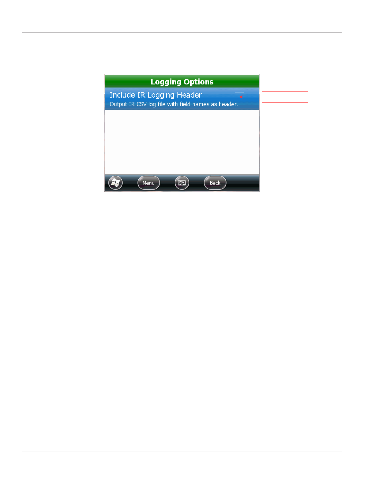
SETTINGS
Logging Options
Logging Options is an optional function used to include the header with the IR CSV output file. Access Logging Options from
Settings on the ORION Endpoint Utility menu.
Tap to select
Figure 111: Logging Options screen
1. Tap the check box to select the option. Tap the check box again to remove the selection.
2. Tap the Back button to return to the Settings screen.
Page 66 April 2014ORION® Endpoint Utility for Trimble® Ranger 3
Page 67

SETTINGS
Prole Extraction Defaults
Profile Extraction Defaults is an optional function used to select a default test circle for ENC and RTR endpoints, and/or a default drive circle for gas endpoints. Access Profile Extraction Defaults from Settings on the ORION Endpoint Utility menu.
If a test circle is selected here, it will display as the default on the ORION Profile Extraction screen during profile extraction
with ENC or RTR endpoints. If a drive circle is selected here, it will display as the default on the ORION Profile Extraction screen
during profile extraction with gas endpoints.
Figure 112: Profile Extraction Defaults screen
1. Tap an option to display a list of test circles or drive circles.
2. Tap to select an option on the list that will be the default.
Result: The defaults selected display next to the option as shown in Figure 113.
Figure 113: Test circles and drive circle defaults selected
3. Tap the Back button to return to the Settings screen.
Page 67 April 2014 ORION® Endpoint Utility for Trimble® Ranger 3
Page 68

SETTINGS
Page 68 April 2014ORION® Endpoint Utility for Trimble® Ranger 3
Page 69

APPENDIX
APPENDIX
Page 69 April 2014 ORION® Endpoint Utility for Trimble® Ranger 3
Page 70

GLOSSARY
GLOSSARY
ADE Absolute digital encoder (ADE) is a position-based encoder that senses the position of each
number wheel to determine the reading for touch and AMR/AMI systems. The ADE displays as
”ENC“ on the software screens.
AMR Automated meter reading system that uses radio frequency technology to transmit meter
readings between an endpoint and a data collection device.
C700D Endpoint type exclusively used for connectivity with Elster/AMCo C700 digital encoders.
ENC Used in the software to denote a three-wire encoder, including the Absolute Digital Encoder.
endpoint A communication device located at the meter that encodes and communicates reading data to
a data collection device (handheld, laptop computer or gateway).
HR-E High resolution absolute encoder with eight-wheel mechanical display. The HR-E displays as
”HRE“ on the software screens.
HR-E LCD High resolution electronic encoder with digital display. The HR-E LCD displays as ”ELCD“ on the
software screens.
ORION CE The ORION Classic endpoint is a one-way local automated meter reading (AMR) system which
communicates with a mobile receiver designed to read ORION water and gas endpoints. The
receiver has Frequency Hopping Spread Spectrum (FHSS) technology to minimize interference
and eliminate FCC licensing.
ORION Cellular The ORION Cellular endpoint is a two-way water endpoint that utilizes existing cellular
infrastructure to deliver meter reading data to the utility via the cellular network.
ORION Field Application The route meter reading software application for the handheld.
ORION ME, ORION SE The ORION Migratable and ORION Fixed Network endpoints are two-way utility management
solutions. ORION Migratable (and ORION Fixed Network in mobile mode) endpoints
communicate with a mobile transceiver designed to receive signals from and send signals to
ORION Migratable and Fixed Network water and gas endpoints. The transceiver has
Frequency Hopping Spread Spectrum (FHSS) technology to minimize interference and
eliminate FCC licensing.
reading data
management software
RF Radio frequency.
RSSI Received Signal Strength Indicator is a receiver designed to pick up radio frequency (RF) signals
RTR The Badger Meter Recordall® Endpoint Register (RTR) is used in conjunction with Recordall disc,
Refers to the Badger Meter reading data management software which acts as an interface
between the utility's billing software and the meter reading devices. The handheld software
will load route information from the reading data management software and unload meter
information to the reading data management software.
and generate an output equivalent to the signal strength.
turbo, compound and fire series water meters to measure totalized flow through the meter and
output a signal to Badger Meter meter reading products.
Page 70 April 2014ORION® Endpoint Utility for Trimble® Ranger 3
Page 71

Transceiver or Receiver
CONNECTING AN EXTERNAL MOBILE TRANSCEIVER OR RECEIVER
CONNECTING AN EXTERNAL MOBILE TRANSCEIVER OR RECEIVER
For handhelds configured with an internal transceiver or receiver, one external ORION Migratable mobile transceiver or
ORION Classic mobile receiver can be connected to read ORION endpoints.
1. Place the magnetic mount antenna on the vehicle roof. Ensure that the free area around the base of the antenna
equals the antenna height.
OTE:N The antenna must be at least two feet away from other antennas and the cable must be in good condition.
2. Press the green power key on the handheld keypad.
3. If the handheld has an internal ORION Migratable transceiver, connect an ORION Classic mobile receiver using the
receiver's communication cable. Plug the communication cable into the top of the mobile receiver and insert the
nine-pin serial end into the port at the bottom of the handheld.
or
If the handheld has an internal ORION Classic receiver, connect an ORION Migratable mobile transceiver using the
transceiver's communication cable. Plug the smaller end of the communication cable into the top of the mobile
transceiver and the larger end into the USB port at the bottom of the handheld.
OTE:N You can also connect an external ORION mobile transceiver to a handheld with an internal ORION Migratable
transceiver, or connect an external ORION mobile receiver to a handheld with an internal ORION Classic
receiver. The external connection increases the radio range for meter reading.
4. Connect the cable from the magnetic
mount antenna to the RF connector
at the top of the mobile transceiver
or receiver and hand tighten so the
connection is secure.
Magnetic
Mount
Antenna
Handheld with
External Connection
5. The mobile transceiver and receiver
require a DC power source. Plug the
transceiver or receiver DC power cable
into the bottom of the transceiver or
receiver and plug the other end into the
Magnetic
Mount
Antenna
Cable
vehicle's interior DC power source (utility
source or cigarette lighter).
6. Switch on the mobile transceiver or
receiver connected to the handheld.
OTE:N Make sure to switch on the
mobile transceiver or receiver
connected to the handheld
ORION
Communication Cable to
USB or Serial Port
before starting any
ORION software.
DC Power Connector
OTE:N Refer to the installation documents titled, ORION ME FHSS Mobile Transceiver and ORION CE FHSS Mobile
Receiver, available at www.badgermeter.com, for status indicators and replacement parts.
7. Start the ORION Endpoint Utility software. For instructions, see "Program Startup And Exit" onpage8.
8. Navigate to Settings> Hardware Settings and set the appropriate COM ports. See "Hardware Settings" onpage63
for more information.
ONLY ONE EXTERNAL MOBILE TRANSCEIVER OR RECEIVER CAN BE CONNECTED TO THE HANDHELD. CONNECTING
MORE THAN ONE WILL REDUCE SYSTEM PERFORMANCE.
Page 71 April 2014 ORION® Endpoint Utility for Trimble® Ranger 3
Page 72

USING THE HANDHELD KEYPAD
USING THE HANDHELD KEYPAD
Left = Bottom left screen
command
Right = Bottom right
screen command
Windows® Start
Circle shortcut - Can be
programmed as barcode
scanner button
Dash/Hyphen
Fn (Function) key +
Yellow label key =
Hot Key function
Yellow label
denotes
Hot Key
Clear contents of the
selected field
APP MENU and COMM MODE
buttons are programmable
Navigate elds on screen with
right/left/up/down arrows
Center key = select or enter
Numeric keys
Alpha keys
On/O power
OTE:N For complete information on the Trimble Ranger handheld, refer to the ORION Automated Meter Reading System for
Trimble Ranger 3 user manual, which can be found at www.badgermeter.com.
Page 72 April 2014ORION® Endpoint Utility for Trimble® Ranger 3
Page 73

HANDHELD FACTORY RESET/CLEAN BOOT
HANDHELD FACTORY RESET/CLEAN BOOT
Use this procedure before installing new software on the handheld.
THIS PROCEDURE RESETS THE TRIMBLE RANGER TO "FACTORY FRESH" CONDITION AND REMOVES ALL PREVIOUSLY
ADDED SOFTWARE, INCLUDING ANY BADGER METER SOFTWARE APPLICATIONS.
Start the factory reset procedure with the handheld powered on.
1. Press and hold the green power key. When the countdown timer starts, release the green power key.
Result: The Power Menu displays.
2. Tap the Reset button on the Power Menu and immediately press and hold BOTH the green power key AND the
RIGHT key on the handheld keypad.
Press &
hold
Press &
hold
3. When the Clean Boot screen appears, release both the green power key and the RIGHT key.
4. Use the up/down navigation arrows on the keypad
to select the Ok button on the screen. Then press
the ENTER key on the keypad only if you want to
completely clear the handheld.
OTE:N Tapping does not work on the Clean Boot
screen. Use the keypad.
Result: Several screens display during the next few
seconds: Blank screen, "Scanning...Wait" screen,
Windows Embedded screen, Finalizing screen, blank
screen again, and then the Windows Embedded screen
again.
5. Touch the handheld screen to start the reset process as instructed on the screen.
6. Align the touch screen by tapping the cross hairs. Continue to tap the cross hairs until the screen aligns.
7. At the Password screen, tap Skip.
8. Tap the Complete screen to nish the reset.
OTE:N After performing a factory reset, the handheld date and time need to be reset. Tap Windows Start> Settings>
Clocks & Alarms to set the correct time and date.
Page 73 April 2014 ORION® Endpoint Utility for Trimble® Ranger 3
Page 74

IR PROGRAMMING BRACKET
IR PROGRAMMING BRACKET
An optional IR Programming Bracket (PN: 65917-001) can be used
to assist in reading ORION endpoints. The bracket allows you to be
hands-free when using the IR programming cable and facilitates
correct alignment between the IR optical read head and the IR
port on the endpoint.
The larger end (bottom) of the bracket fits on the bottom of the
endpoint. The endpoint cable fits through one of the open sides.
No tools are required.
IR programming bracket
1. Hold the endpoint upside down and position the bottom of the bracket over the tabs at the bottom of the endpoint.
The bracket should t easily over the bottom of the endpoint. Turn clockwise so it catches on the endpoint tabs to
lock it in place.
Endpoint IR LED port
Endpoint tab
Tool placed over endpoint tab
Top view
OTE:N Do NOT insert the IR head into the slot of the bracket before placing the bracket on the endpoint. The
bracket will not fit on the endpoint if the IR head is inserted.
2. Place the IR head in the slot, facing either direction. The IR head ts snugly in the slot. Make sure the IR head is
inserted straight in the slot.
OTE:N The IR head is in the correct position for a read but does not sit directly over the LED port of the endpoint.
Incorrect placement – IR head angled
Correct placement – IR head straight
3. When nished using the bracket, remove the IR head. Then turn the bracket counterclockwise to loosen it and
remove it from the endpoint.
Page 74 April 2014ORION® Endpoint Utility for Trimble® Ranger 3
Page 75

STATUS CODES
STATUS CODES
Status codes are displayed on several of the screens within the software. The following is a list of status codes and
their descriptions.
Status Code Description
CR Cover Removal (gas only)
EE Encoder/Register Error
IR Programmed via IR – endpoint was programmed using the infrared cable
LB Low Battery
LK Leak
MMI Mobile Mode Indicator
NU No Usage
REV Reverse Flow (encoder or gas only)
T Tamper
VALID COM PORTS
See "Hardware Settings" onpage63 to adjust the COM port settings.
Technology COM Port
External ORION Classic or VersaProbe COM1
GPS - Ranger 3 only COM2
Not applicable COM3
External ORION Migratable COM4
Not applicable COM5
Not applicable COM6
Internal ORION Classic or
ORION Migratable technology
Bluetooth VersaProbe COM8
Bluetooth VersaProbe COM9
ORION In Home Display COM10
COM7
Page 75 April 2014 ORION® Endpoint Utility for Trimble® Ranger 3
Page 76

GAS METER DRIVE ROTATION
GAS METER DRIVE ROTATION
The table below displays the drive gear rotation direction for common gas meter makes/models.
CW = clockwise
CCW = counter clockwise
Gas Meter ORION Type Direction of Rotation
Elster®/American
AC-250 AMCO Res CCW
AL-425 AMCO Res CCW
AC-630 AMCO Res CCW
AC-800 AMCO Res CCW
AL-800 AMCO C&I CW
AL-1000 AMCO C&I CW
Itron®/Actaris®
Metris 250 Itron/ActarisRes CCW
400A Itron/ActarisRes CCW
675A Itron/Actaris C&I CW
800A Itron/Actaris C&I CW
1000A Itron/Actaris C&I CW
Sensus®
Cubix 250 Sensus Res CCW
R275 Sensus Res CCW
R315 Sensus Res CCW
415 Sensus 415 CCW
750 Sensus C&I CCW
1000 Sensus C&I CCW
Page 76 April 2014ORION® Endpoint Utility for Trimble® Ranger 3
Page 77

TECHNICAL SUPPORT
TECHNICAL SUPPORT
Errors are uncommon, so it is important to report all occurrences of error windows to Badger Meter Technical Support.
What to Report
Provide the following information if possible when contacting Technical Support:
• The handheld screen that was active
• The steps being performed at the time
• Any entries that were made on the screen
• The error message, including any error code and explanation that is shown
• The current condition of the laptop
The Technical Support Specialist may request you to fax notes or other information to assist in the investigation.
Contact Badger Meter Technical Support
Phone: 800-456-5023
Email: TechSupport@BadgerMeter.com
Fax: 888-371-5982
Page 77 April 2014 ORION® Endpoint Utility for Trimble® Ranger 3
Page 78

INTENTIONAL BLANK PAGE
Page 78 April 2014ORION® Endpoint Utility for Trimble® Ranger 3
Page 79

INTENTIONAL BLANK PAGE
Page 79 April 2014 ORION® Endpoint Utility for Trimble® Ranger 3
Page 80

Making Water Visible®
ADE, ORION, ReadCenter and RTR are registered trademarks of Badger Meter, Inc. Other trademarks appearing in this document are the property of their respective entities.
Due to continuous research, product improvements and enhancements, Badger Meter reserves the right to change product or system specications without notice, except to the
extent an outstanding contractual obligation exists. © 2014 Badger Meter, Inc. All rights reserved.
www.badgermeter.com
The Americas | Badger Meter | 4545 West Brown Deer Rd | PO Box 245036 | Milwaukee, WI 53224-9536 | 800-876-3837 | 414-355-0400
México | Badger Meter de las Americas, S.A. de C.V. | Pedro Luis Ogazón N°32 | Esq. Angelina N°24 | Colonia Guadalupe Inn | CP 01050 | México, DF | México | +52-55-5662-0882
Europe, Middle East and Africa | Badger Meter Europa GmbH | Nurtinger Str 76 | 72639 Neuffen | Germany | +49-7025-9208-0
Europe, Middle East Branch Office | Badger Meter Europe | PO Box 341442 | Dubai Silicon Oasis, Head Quarter Building, Wing C, Office #C209 | Dubai / UAE | +971-4-371 2503
Czech Republic | Badger Meter Czech Republic s.r.o. | Maříkova 2082/26 | 621 00 Brno, Czech Republic | +420-5-41420411
Slovakia | Badger Meter Slovakia s.r.o. | Raciansk a 109/B | 831 02 Bratislava, Slovakia | +421-2-44 63 83 01
Asia Pacific | Badger Meter | 80 Marine Parade Rd | 21-04 Parkway Parade | Singapore 449269 | +65-63464836
China | Badger Meter | 7-1202 | 99 Hangzhong Road | Minhang District | Shanghai | China 201101 | +86-21-5763 5412
Excerpt from Legacy Document #: ORI-UM-00185-EN
 Loading...