

Page 1

LM OG-AM series
User Manual
LM OG-AM
LM OG-TAERM
LM OG-CNDAM
Oval gear meters with MID approved register and integrated
datalogger
LM_OG-AM_BA_02_1163 (May 2019)
Page 2

LM OG-AM series
CONTENT
1. Disclaimer ................................................................................................................................................................................................................................... 1
2. Basic safety recommendations .......................................................................................................................................................................................... 1
3. Before putting into operation ............................................................................................................................................................................................ 2
3.1 Recommended filter sizes ........................................................................................................................................................................................ 3
4. Warranty ...................................................................................................................................................................................................................................... 3
5. Details of unit operation LM OG-AM series ................................................................................................................................................................... 4
5.1 RESET button ................................................................................................................................................................................................................. 4
5.2 Datalogger: A non-volatile memory .................................................................................................................................................................... 4
5.3 Battery ............................................................................................................................................................................................................................. 4
5.4 Interruption of batch process ................................................................................................................................................................................. 4
5.5 Functional control ....................................................................................................................................................................................................... 4
5.6 Totalizer........................................................................................................................................................................................................................... 5
5.7 Monitoring of false pulses for MID conform meters ...................................................................................................................................... 5
5.8 Installation procedure LM OG ................................................................................................................................................................................ 5
6. Programming of LM OG-AM and LM OG-TAERM series ........................................................................................................................................... 6
7. Calculating the correction factor....................................................................................................................................................................................... 7
7.1 Calculation based default settings ....................................................................................................................................................................... 7
7.2 Recalculation of an existing correction factor ................................................................................................................................................. 7
8. Pulse output at register OG-TAERM ................................................................................................................................................................................. 7
9. Browse and program data logger ..................................................................................................................................................................................... 8
9.1 Search for a dispense ................................................................................................................................................................................................. 8
9.2 Programming the datalogger ................................................................................................................................................................................ 9
10. Display correction factor .................................................................................................................................................................................................... 9
11. Checksum & serial number ............................................................................................................................................................................................ 10
12. Status messages ................................................................................................................................................................................................................. 10
13. Changing the Battery ....................................................................................................................................................................................................... 10
14. MID approval ....................................................................................................................................................................................................................... 11
15. Manufacturer declaration ............................................................................................................................................................................................... 11
16. DIN ISO and EMC certificate ........................................................................................................................................................................................... 11
17. Return of goods for repair / Harmlessness declaration....................................................................................................................................... 11
Page II LM_OG-AM_BA_02_1163 May 2019
Page 3

Disclaimer
LM OG-AM
Standard inline meter
LM OG-KAM
Coated standard inline meter
LM OG-CDAM
Pistol meter with handle, sightglas and swivel
LM OG-CNDAM
Pistol meter with handle, sightglas, swivel and outlet
LM OG-TAERM
Inline meter with pulse output
LM OG-TAERKM
Coated inline meter with pulse output
1. DISCLAIMER
The user/purchaser is expected to read and understand the information provided in this manual, follow any listed safety
precautions and instructions and keep this manual with the equipment for future reference. The information in this manual
has been carefully checked and is believed to be entirely reliable and consistent with the product described. However, no
responsibility is assumed for inaccuracies, nor does Badger Meter assume any liability arising out of the application and use of
the equipment described. Should the equipment be used in a manner not specified by Badger Meter, the protection provided
by the equipment may be impaired and the warranty voided. The meter is conform to the MID regulations for liquids other
than water.
2. BASIC SAFETY RECOMMENDATIONS
Before installing or using this product, please read this instruction manual thoroughly. Only qualified personnel should install
and/or repair this product. If a fault appears, contact your distributor.
Installation
Do not place any unit on an unstable surface that may allow it to fall.
Never place the units above a radiator or heating unit.
Route all cabling away from potential hazards.
Isolate from the mains before removing any covers.
Power connection
Use only the type of power source suitable for electronic equipment. If in doubt, contact your distributor. Ensure that any
power cables are of a sufficiently high current rating. All units must be earthed to eliminate risk of electric shock. Failure to
properly earth a unit may cause damage to that unit or data stored within it.
Protection class
Following devices have protection class IP65:
All devices have to be protected against dripping water, water, oils, etc.
Setup & operation
Adjust only those controls that are covered by the operating instructions. Improper adjustment of other controls may result
in damage, incorrect operation or loss of data.
Cleaning
Switch off all units and isolate from mains before cleaning.
Clean using a damp cloth. Do not use liquid or aerosol cleaners.
May 2019 LM_OG-AM_BA_02_1163 Page 1
Page 4
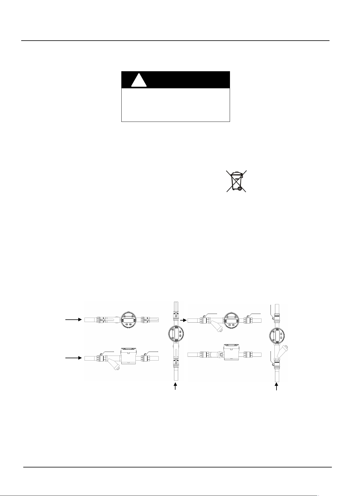
Before putting into operation
!
Strainer
Strainer
Flow direction
Repair of faults
Disconnect all units from power supply and have it repaired by a qualified service person if any of the following occurs:
WARNING
Failure to adhere to these safety
instructions may result in damage to the
product or serious bodily injury.
RoHs
Our products are RoHs compliant.
Battery disposal
The batteries contained in our products need to be disposed of as per your
local legislation acc. to EU directive 2006/66/EG.
3. BEFORE PUTTING INTO OPERATION
Please check that the technical data of the installation match with those of the lube meter, for example connections, pressure,
flow range and medium. Once the meter has been installed, please make sure that no air, pressure shocks or particles can
damage the meter.
Read the following information and have a thorough understanding before proceeding with meter installation. Only
qualified personnel should perform meter installation.
• Install a strainer or Y or basket as close to the inlet side of the meter as possible. Strainers prevent dirt and other fluid
contaminants from impeding meter performance. Strainers require periodic cleaning, as clogged strainers also impede
meter performance. Contact your local representative for specific information, per your specific application.
Figure 1: Meter installation
Page 2 LM_OG-AM_BA_02_1163 May 2019
Page 5

Warranty
Filter / Pore size (in mesh)
Filter / Pore size (in mm)
½"
60
0,250
• Turn off any associated pumps to reduce line pressure and slowly fill the line and meter with fluid before restarting
pumps. Doing so reduces the possibility of meter damage caused by errant air pressures in the line and meter.
• Make sure all pipe conforms to the same pressure output rating as the pump.
• Make sure to apply thread sealant to all pipe threads.
• Make sure to install the meter as shown in figure 1.
• Check for and repair leaks upon initialization of fluid flow.
3.1 Recommended filter sizes
Please check all connections to leakage. After the installation we recommend to perform several transactions into an
approved piston. Should the use of different oil viscosities show discrepancies by the error limit, it can be immediately
corrected at the site. The pretested meters can be calibrated by technicians or the officials of the national authorities (MID).
4. WARRANTY
Badger Meter warrants meters and parts manufactured by it and supplied hereunder to be free from defects in materials and
workmanship for a period of 24 months from date of shipment. If within such period any meters or parts shall be proved to
Seller´s satisfaction to be defective, such meters or parts shall be repaired or replaced at Seller´s option. Seller´s obligation
hereunder shall be limited to such repair and replacement and shall be conditioned upon Seller´s receiving written notice of
any alleged defect within 10 days after its discovery and, at Seller´s option, return of such meters or parts to Seller, f.o.b. its
factory. THE FOREGOING WARRANTY IS EXCLUSIVE AND IN LIEU OF ALL OTHER EXPRESS OR IMPLIED WARRANTIES
WHATSOEVER INCLUDING BUT NOT LIMITED TO IMPLIED WARRANTIES (EXCEPT OF TITLE) OF MERCHANTABILITY AND FITNESS
FOR A PARTICULAR PURPOSE. Badger Meter shall not be liable for any defects attributable to acts or omissions of others after
shipment, nor any consequential, incidental or contingent damage whatsoever.
May 2019 LM_OG-AM_BA_02_1163 Page 3
Page 6

Details of unit operation LM OG-AM series
5. DETAILS OF UNIT OPERATION LM OG-AM SERIES
5.1 RESET button
The display of the resettable totalizer (batch register) can be put to zero by pushing the RESET button. A RESET is not
possible during a batch process. The RESET of the non-resettable totalizer is only possible in the MID secured area of the
register configuration. Each RESET will save the dispensed quantity in the datalogger, but only if the quantity is equal or
bigger than 0,5 liters.
5.2 Datalogger: A non-volatile memory
The register is fitted with a memory device to store measurement results until their use or to keep a record of commercial
transactions, providing proof in the event of a dispute. Devices used to read stored information are considered as included in
the memory devices. It is not required that the parties interested in a transaction shall be provided continuously with the
results of measurement, but only that they shall have access to these results (for example, in the event of a dispute). In
addition, in the case of self-service (filling station, truck filling station) the owner of the measuring system is considered to
have access to the indications of the measuring system even when he does not use this possibility in practice (OIML R117-1,
Chapter 3.5).
5.3 Battery
As soon as the capacity of the battery is less than 10%, “LBat” is displayed on the electronic
register. The battery should then be replaced within the next two months. The battery is
exchangeable in all meters of the LM OG-AM and OG-TAERM series while opening the cover
on the front of the register. No data are lost, they are securely saved in an EEPROM memory except of the date and time. To keep the date and time settings, you have to reinsert the
battery within 30 minutes. See also chapter 13.
5.4 Interruption of batch process
By releasing the meter trigger, the batch process is interrupted. When pulled again, the batch process will be continued at the
very point where it was interrupted, unless the RESET button has been pushed in the meantime. The display will remain
unchanged during the interruption. If the batch process is interrupted by external source – e.g. failure of a transfer pump – the
procedure is the same.
5.5 Functional control
In normal operation, the register board totalizes flow in the lube meter by sensing reed switch actions. The batch display may
be reset to zero by momentarily pressing the RESET button on the front panel. This action will set the batch accumulator to
zero and cause the register to enter a self-test mode. For the self-test, it is necessary that the display is activated with all
numerics set to “8” and all other indicators set to “on” for a period of 0,8 seconds. If flow or reed switch action takes place
during the self-test period, the resultant pulses are processed as normal flow accumulations. This accumulation of flow can
only be reset by pressing the RESET button.
During the self-test period, the meter will compare the double redundant storage of the correction factor, the unit of measure
and direction of rotation. If one of the values do not correspond, the register will show a series of dashes (- - - -) and will
become inoperative.
If flow sensing or reed switch action is present at any time and it is not preceded by a pressing of the RESET button, the flow
accumulations will be added to the value already present in the batch accumulator.
Page 4 LM_OG-AM_BA_02_1163 May 2019
Page 7

Details of unit operation LM OG-AM series
5.6 Totalizer
The total dispense quantity is shown in the bottom line. The factory programmed correction factor results from accuracy
testing of bare meter with the mounted electronic register: Pressing the TOTAL and the RESET button simultaneously for 3
seconds will show the programmed correction factor.
Resettable totalizer: 999,999 L (over thousand 9999,99 L)
Non resettable totalizer: 99999 L
As soon as volume signals come in, all keyboard commands will be ignored!
As soon as pulses are internally accumulated, the keypad is out of function!
5.7 Monitoring of false pulses for MID conform meters
During measurement, the microprocessor controls the phase position of both reed switches (30° to 150° phase shift).
Errors caused by incorrect phase sequence:
If more than two (2) phase errors are noted after a RESET, the LCD display is flashing (1 second interval). This type of error is
resettable by depressing the RESET button.
If it is not possible to stop the flashing, there is another fault and the register has to be exchanged.
The flashing can e. g. also be caused by a short-time reverse flow when starting up the oil dispense system, or by an
insufficiently areated oil pipe (pressure shocks). This can be prevented by installing an appropriate non-return valve.
FLDIR will indicate a reverse flow, quantity display will change to ---,--
REED will indicate a missing input channel, quantity display will change to ---,--
Errors in stored variables:
(i.e. correction factor, unit of measure, direction of rotation)
These errors are indicated by a series of dashes across the display and are not resettable. The register has to be removed from
service.
5.8 Installation procedure LM OG
The meter series LM OG is equipped with BSP female threads. In order to obtain a leakage-free connection from the meter to
the hose, the hose end must have an appropriate BSP male thread.
We recommend to proceed as follows before screwing in:
1) Clean both threads from fat.
2) Brush the male thread at the hose with liquid sealant (e.g. Eurolock 310100 or equivalent sealing of other manufacturers).
Be careful that no sealing gets into the meter.
3) Screw both parts together. Do not overtighten the screw connection, otherwise the swivel of the meter could be
damaged.
4) The instruction of the sealing manufacturer should be absolutely followed.
5) The meter mounting should only be carried out by authorized specialist staff.
The right selection of the components as well as the mounting in accordance with the regulations is in the responsibility of
the user.
May 2019 LM_OG-AM_BA_02_1163 Page 5
Page 8

Programming of LM OG-AM and LM OG-TAERM series
01
07
02
08
03
09
03
10
04
11
05
12
06
6. PROGRAMMING OF LM OG-AM AND LM OG-TAERM SERIES
The units of measure and the correction factor can be configured in the programming mode. A program button on the
backside of the register will enable the mode, only accessible when the register has been removed from the meter. Removing
the register from the meter will break the sealing. This seal has to be restamped by the national authorities (MID).
Turn on the register by pressing the
TOTAL button.
By pressing the programming button on
the backside of the register you will enter
the programming mode.
The measuring unit will flash and can be
changed by pressing the RESET button (L,
GAL, QT, PT).
To move forward press the TOTAL button.
Press “TOTAL” to change the k-factor. The
number to be changed is flashing and can
be modified with “RESET”.
To change the next number, press
“TOTAL”.
The second number can now be changed.
To move to the next number, press
“TOTAL” again.
The fifth number can now be changed.
To move forward, press “TOTAL” again.
The arrow for the flow direction flashes
now. Use RESET to change or TOTAL to
move forward.
By pressing the programming button on
the backside of the register you will quit
the programming mode.
The register went into the sleep mode.
To wake up the register, press the RESET
button.
The third number can now be changed.
To move to the next number, press
“TOTAL” again.
The fourth number can now be changed.
To move to the next number, press
“TOTAL” again.
Press „RESET“ for 3 seconds and the
register displays the checksum and serial
number in the bottom line.
Page 6 LM_OG-AM_BA_02_1163 May 2019
Page 9

Calculating the correction factor
Wiring only for MDS2000 Management System
Wiring for other Management System
MDS version included a meter detection
Viscosity 440 mPas
OUTPUT 2
GREEN
WHITE
GND
BROWN
6-24 VDC
YELLOW
OUTPUT 1
OUTPUT 2
GREEN
WHITE
GND
BROWN
6-24 VDC
YELLOW
7. CALCULATING THE CORRECTION FACTOR
Two different ways are described below to eliminate the existing deviation of a meter.
The reference quantity (“quantity dispensed”) should always be measured with an appropriate measuring device.
• Approved piston or bell prover
• Approved gravimetric method
7.1 Calculation based default settings
Example:
Quantity dispensed: 5,000 liters
Quantity displayed: 4,990 liters
Correction factor k: 4,990 / 5,000 = 0,9980
7.2 Recalculation of an existing correction factor
Example:
Quantity dispensed: 5,000 liters
Quantity displayed: 5,015 liters
Correction factor k: 5,015 / 5,000 = 1,003
Factor k about 1,0000
The existing correction factor would be for example: 0,9960
Calculation: 0,9960 x 1,003 = 0,9989
The new correction factor is 0,9989
8. PULSE OUTPUT AT REGISTER OG-TAERM
The pulse output on the LM OG-TAERM register has a rating of 2x100 PPL with a 90°-135° phase-shift. Any irregular use or
malfunction will be indicated on the error channel with permanent signal on high. The correction factor will also correct the
output signal.
Flow direction - Inlet Top to Bottom Power supply
Output channel 1 = green 6–24 VDC = yellow
Output channel 2 = white (Error channel) GND = brown
Flow direction - Inlet Bottom to Top
Output channel 1 = white (Error channel)
Output channel 2 = green
May 2019 LM_OG-AM_BA_02_1163 Page 7
Page 10

Browse and program data logger
Pressing the RESET button once will bring you to the next older data entry, no matter if you are on the Date, Time
Pressing the TOTAL button once will bring you to the next newer data entry, no matter if you are on the Date,
Date
Time
Qty
Batch
19.09.12
17:55
2,42
0081
19.09.12
16:23
4,42
0080
etc…
18.09.12
17:23
4,53
0068
18.09.12
17:12
7,24
0067
18.09.12
15:46
12,78
0066
etc…
Sample content data logger
5s
5s
Previous day
1x
Next lower level
2s
Next batch
2s
Next batch
1x
Next lower level
2s
Control buttons
Standard display
0.000 L
19.09.12
18.09.12
17.23
17.12
15.46
12.78 L
Level – Date
Level – Date
Level – Time
Batch 0068
Level – Time
Batch 0067
Quantity
Batch 0066
Quantity
Batch 0066
9. BROWSE AND PROGRAM DATA LOGGER
Pushing the RESET will automatically save the current dispense in the datalogger, if the quantity is bigger than 0,49 liters. The
datalogger is capable to store 500 dispenses, any additional transaction will overwrite the oldest one without notice.
9.1 Search for a dispense
The sample below shows how to search for a dispense on a certain day. Known is the date and time of the dispense:
18.09.2012 15:46
Result: The dispensed quantity was 12,78 liters.
Opens Alibi Memory
8793 TOTAL
0081
0068
19.09.2012 Current day
Last batch
18.09.2012 Day before
Batch 0068 = is the latest on this day
0068
0067
0066
0066
Level –
Level –
or Quantity menu level. If you push the RESET twice and hold the button (within 1s), the data will scroll
automatically.
Pressing the RESET for more than 2s will bring you to the next lower menu level.
Time or Quantity menu level. If you push the TOTAL twice and hold the button (within 1s), the data will scroll
automatically.
Pressing the TOTAL for more than 2s will bring you to the next higher menu level.
Page 8 LM_OG-AM_BA_02_1163 May 2019
Page 11

Display correction factor
5s
5s
Opens Configuration
5s
5s
Move to DATE
Move to ERASE
2s
Change to YES
1x
Confirm ERASE
0.000 L
19.09.12
15.32
20.09.10
Nein
Ja
----
Level – Date
Use the program button to confirm
the ERASE
The ERASE will last for about 45s
1.0000
9.2 Programming the datalogger
Below you will find the procedure to change time and date. The date can only be changed with the program button on the
backside, which is only accessible when the register has been removed from the meter. Removing the register from the meter
will break the sealing. This seal has to be restamped by the national authorities (MID).
The ERASE button removes all the logged dispenses; it does not affect time and date.
Opens Alibi Memory
8793 TOTAL
0081
Zeit
register backside
Datum
Loschen
Loschen
register backside
Standard display
19.09.2012 Current day
Last batch
Change the time by using the RESET and
TOTAL to move forward
Change the date by using the RESET
and TOTAL move forward
Use the RESET button to change to
YES
NOTE: If no button has been pressed for more than 30 seconds, the register will automatically move back to the standard
display without saving the last entry.
10. DISPLAY CORRECTION FACTOR
To verify the programmed correction factor, press TOTAL and RESET for 2 seconds.
Correction factor
May 2019 LM_OG-AM_BA_02_1163 Page 9
Loschen
Page 12

Checksum & serial number
Picture 1:
Picture 2:
Picture 3:
up the register
Picture 4:
3A33.07 L
3A33 = Checksum over the MID relevant source code
07
Checksum
A = The year of production
AC001
Serial number
0.000 L
Wrong flow direction. Actual flow does not match with the programmed flow direction. FLDIR
flash
Programming of
LM OG
-.--- L
Channel missing due to broken reed switch
to dashes.
Call service for replacement
-.--- L
Lost date due to power fa
DATE flash
again. Quantity changes to dashes.
11. CHECKSUM & SERIAL NUMBER
Pressing RESET for 3 seconds will display the checksum and serial number in the bottom line.
AC001 TOTAL
= Sequential version number, not MID relevant
= Sequential alphanumeric number
12. STATUS MESSAGES
Floir TOTAL
Reed TOTAL
Datum TOTAL
es in the bottom line, the quantity will change to dashes. See chapter 6 - step 8:
-AM and LM OG-TAERM series.
REED flashes in the bottom line, the quantity changes
.
ilure, i.e. slow battery exchange.
es in the bottom line, meter will not count anymore until the date has been entered
See chapter 13: Changing the battery
13. CHANGING THE BATTERY
Important – Before starting the replacement:
The battery has to be replaced within 30 minutes, otherwise you will lose the date and time setting. The display would show
"Date" in the bottom which indicates that the date is lost. The quantity display will change to dashes "- - - -". To reconfigure
the date, you would have to remove the register, which is sealed by a MID label.
Please proceed as follows:
Loosen the battery cover
Battery: Lithium CR123A
Page 10 LM_OG-AM_BA_02_1163 May 2019
Take out the battery
Insert the new battery and
press the reset button to wake
Insert the battery cover, then
screw the battery cover tight
Page 13

14. MID APPROVAL
You will find all approvals applying to this meter series under
www.badgermeter.de/en/downloads/approvals/
15. MANUFACTURER DECLARATION
You will find all CE declarations applying to this meter series under
www.badgermeter.de/en/downloads/ce-declarations/
16. DIN ISO AND EMC CERTIFICATE
Please refer to our valid DIN ISO and EMC certificate under
www.badgermeter.de/en/downloads/certificates/
MID approval
17. RETURN OF GOODS FOR REPAIR / HARMLESSNESS DECLARATION
Please refer to our claims return form/harmlessness declaration under
www.badgermeter.de/en/service/return-of-goods.html
May 2019 LM_OG-AM_BA_02_1163 Page 11
Page 14

Return of goods for repair / Harmlessness declaration
Page 12 LM_OG-AM_BA_02_1163 May 2019
Page 15

Return of goods for repair / Harmlessness declaration
May 2019 LM_OG-AM_BA_02_1163 Page 13
Page 16

www.badgermeter.de
 Loading...