

Page 1

®
Badger Meter Europa GmbH
MDS2000
Oil management system
INSTALLATION AND
SOFTWARE MANUAL
October 2008
LMS_MDS2000_BA_02_0810
Page 2

Content Page
1. Installation manual ............................................................................................................ 1
1.1 Safety features
1.2. Schemas
1.2.1 Cable requirements ........................................................................................ 2
1.2.2 Oil installation ................................................................................................. 3
1.2.3 Connections for the junction box .................................................................... 4
1.2.4 Connections for the printer, the network & the internal PC card ..................... 5
1.2.5 Connections for the external PC card ............................................................. 6
1.2.6 Connections for the keypad ............................................................................ 7
1.2.7 Change of the address of the display ............................................................. 8
1.2.8 Connections for the solenoids ........................................................................ 9
1.2.9 Connections for the power and single pulse transmitters ............................. 10
1.2.10 Connections for the power and dual channel pulse transmitters .................. 11
1.2.11 I/O card connectors ...................................................................................... 12
1.3. Cabling
1.3.1 The network .................................................................................................. 13
1.3.2 The power ..................................................................................................... 14
1.3.3 The terminal links .......................................................................................... 16
1.3.4 The solenoid valves ...................................................................................... 16
1.3.5 The pulse transmitters .................................................................................. 17
1.3.6 The printer cable ........................................................................................... 18
1.4. Network
1.4.1 Installation procedure ................................................................................... 18
1.4.2 Logic structure of the MDS network .............................................................. 19
1.4.3 How does the network work? ........................................................................ 19
1.4.4 Level 1 .......................................................................................................... 20
1.4.5 Level 2 .......................................................................................................... 21
1.4.6 Level 3 .......................................................................................................... 22
1.5. Troubleshooting guide
1.5.1 Communication problems ............................................................................. 23
1.5.2 Problems with the display ............................................................................. 24
1.5.3 Problems with the solenoid valves ................................................................ 24
1.5.4 Problems with the pulse transmitters ............................................................ 24
1.5.5 Problems with the printers ............................................................................ 25
1.5.6 Problems with the PC software / interface .................................................... 25
1.5.7 Explanations for the transaction end codes .................................................. 25
1.5.8 Procedure to change the battery .................................................................. 26
..................................................................................................................... 13
.................................................................................................................... 18
........................................................................................................... 1
.................................................................................................................... 2
.............................................................................................. 22
Page 3

Content Page
2. Software manual .............................................................................................................. 26
2.1 Program license agreement
2.2. PC card upgrade
2.2.1 Introduction ................................................................................................... 27
2.2.2 About the PC interface card .......................................................................... 27
2.2.3 PC card installation ....................................................................................... 27
2.2.4 PC minimum requirements ........................................................................... 28
2.2.5 MDS 2000 requirements ............................................................................... 28
2.2.6 PC card hardware installation ....................................................................... 28
2.2.7 PC card software installation ........................................................................ 29
2.2.8 Running the software .................................................................................... 30
2.3. Using the software
2.3.1 Configuration button ..................................................................................... 31
2.3.2 Display button ............................................................................................... 35
2.3.3 Report button ................................................................................................ 36
2.3.4 Dispense button ............................................................................................ 37
2.3.5 Exit button ..................................................................................................... 37
2.4. Export file possibilities
2.4.1 Two possibilities are available ...................................................................... 38
2.4.2 Transaction to disk option ............................................................................. 38
2.4.2.1 How is it working? ......................................................................... 38
2.4.2.2 General description ...................................................................... 39
2.4.2.3 Transactions ................................................................................. 39
2.4.2.4 Responsibility ............................................................................... 40
2.4.2.5 Security ......................................................................................... 40
2.5. Backup - restore or Archive Database
3. Manufacturer´s declaration ............................................................................................. 43
4. Warranty ........................................................................................................................... 44
5. DIN ISO certificate ........................................................................................................... 44
...................................................................................................... 27
.................................................................................................... 31
..................................................................................... 26
.............................................................................................. 38
..................................................................... 41
Page 4

Safety features Page 1/44
1. Installation manual
1.1. Safety features
1. Before installing or using this product, please read the instruction manual
thoroughly.
2. Unpacking: Please check that the product is complete and free from any
damage (check with the further packing list).
3. Only qualified individual should install and/or repair this product.
4. Unplug the MDS 2000 from the electrical outlet before you clean it. Use a clamp
cloth for cleaning and do not use liquid or aerosol cleaners.
5. Do not place the MDS 2000 on an unstable surface that may allow the unit to
fall.
6. Never place the MDS 2000 near or over a radiator or heat register.
7. Use the type of power source indicated on the label (AC power). If you are not
sure of the type of power available, consult your supplier or local electric
company.
8. The MDS 2000 must be equipped with a plug having a third (grounding) pin,
which fits only into a grounding-type outlet. This is a safety feature. The MDS
2000 should not be used without a properly grounded outlet. Failure to properly
ground the MDS 2000 may cause damage to the unit or the data stored.
9. Do not put the MDS 2000 where the cord will be walked on.
An extension cord is not recommended for use with the MDS 2000. If you use
an extension cord, make sure that the total of the ampere ratings on the
products plugged into the extension cord does not exceed the extension cord's
ampere rating. Also, make sure that the total of all products plugged into the
wall outlet does not exceed 15 amperes.
11. Unplug the MDS 2000 from the wall outlet and have it repaired by a qualified
service person under the following conditions:
a) When the power cord or plug is damaged or frayed.
b) If liquid has been spilled into it.
c) If it has been exposed to rain or water.
d) If it does not operate normally when the operating instructions are followed.
Adjust only those controls that are covered by the operating instructions
since improper adjustment of other controls may result in damage and loss
of data.
e) If it has been dropped or damaged.
f) If it exhibits a distinct change in performance, indicating a need for service.
Warning
Failure to adhere to these safety instructions may result in serious bodily injury.
LMS_MDS2000_BA_02_0810
Page 5

Schemas Page 2/44
1.2. Schemas
1.2.1 Cable requirements
18 Volts DC power cable 2 Core + earth 0.75 mm²
Network cable Type 1 twisted pair screened
Apple Talk 9999 Belden or Belden
8451, or Alpha 24561 or
equivalent
Terminal cable Type 2 twisted pair screened by
pair, Belden 9723 or equivalent
Pulse transmitter cable Type 1 twisted pair screened
Solenoid cable 2 core + earth 0.75 mm²
Printer cable Type 3 core screened (or higher)
Suggestion:
For small and medium installations, we suggest to use the same cable for:
- 24 VDC + network
- Terminal cable
- Pulse transmitter (18690) + solenoid
type 2 twisted pair 0.75mm² min. shielded by pair (capacitance ≤ 65 pF/m),
Belden 1474 or equivalent.
LM_MDS2000_BA_02_0810
Page 6

Schemas Page 3/44
1.2.2 Oil installation
LM_MDS2000_BA_02_0810
Page 7

Schemas Page 4/44
1.2.3 Connections for the junction box
2 core 0,75mm power cable + earth
POWER
NETWORK
1 twisted pair
screened
type Alpha 2461
Belden 8451
0V
18V
Can L
TERMINAL
2 twisted pair
shielded by pair (belden 9723)
Schield
Can H
CABLE
LM_MDS2000_BA_02_0810
Page 8

Schemas Page 5/44
1.2.4 Connections for the printer, the network & the internal PC card
Pin 3 - TXD
Pin 7 - GND
Pin 20 - RXDO/CTSO
I/O
TXDO
GND
9DB - to PC
Terminal cable
RXDO / CTSO
CAN H
Shield
CAN L
Key
J 5
LEN
0V
18V
LM_MDS2000_BA_02_0810
Page 9

Schemas Page 6/44
1.2.5 Connections for the external PC card
PC : 9DB
9DB
9DB
I/O
TXDO
GND
RXDO / CTSO
CAN H
Shield
CAN L
Terminal cable
Key
J 5
LEN
LM_MDS2000_BA_02_0810
Page 10

Schemas Page 7/44
1.2.6 Connections for the keypad
PIN 2 - RXD
PIN 7 - GND
PIN 9 - WAND POWER
18V NEUT
18V LIVE
WAND POWER
CTS
RXD
GND
TXD
CAN L
SHIELD
CAN H
0V
24V
Terminal cable
Junction Box
PIN 3 - TXD
PIN 7 - GND
PIN 20 - CTS
Pen
Optical
LM_MDS2000_BA_02_0810
Page 11

Schemas Page 8/44
1.2.7 Change of the address of the display
Display
CAN L
SHIELD
CAN H
18V
0V
Addr. SW1 SW2 SW3 SW4
0 ONONONON
Terminal cable
Junction Box
1 OFF ON ON ON
2 ON OFF ON ON
3OFF OFFONON
4 ONONOFFON
5 OFF ON OFF ON
6ONOFFOFFON
7 OFF OFF OFF ON
8 ONONONOFF
9 OFF ON ON OFF
10 ON OFF ON OFF
11 OFF OFF ON OFF
12 ON ON OFF OFF
13 OFF ON OFF OFF
14 ON OFF OFF OFF
15 OFF OFF OFF OFF
LM_MDS2000_BA_02_0810
Page 12

Schemas Page 9/44
1.2.8 Connections for the solenoids
OP8
+V
OP7
+V
OP6
+V
OP5
+V
OP4
+V
OP3
+V
OP2
+V
OP1
+V
OP0
+V
MAIN AIR
SOLENOID
SOLENOID 8
HOSE 8
SOLENOID 7
HOSE 7
SOLENOID 6
HOSE 6
SOLENOID 5
HOSE 5
SOLENOID 4
HOSE 4
SOLENOID 3
HOSE 3
SOLENOID 2
HOSE 2
FRAME NUT
SOLENOID 1
HOSE 1
KEY SWITCH
key
O
LM_MDS2000_BA_02_0810
Page 13

Schemas Page 10/44
1.2.9 Connections for the power and single pulse transmitters
SPARE
GND
IN8
+V
GND
IN7
IN6
+V
GND
IN5
IN4
+V
GND
IN3
IN2
+V
GND
IN1
IN0
+V
18690
18690
18690
18690
Waste Oil
Level Detector
18690
18690
Hose # 6
Hose # 5
18690
Hose # 2
Hose # 1
18690
Hose # 8
Hose # 7
Hose # 4
Hose # 3
0V
Power
18V
I/O
LM_MDS2000_BA_02_0810
Page 14

Schemas Page 11/44
1.2.10 Connections for the power and dual channel pulse transmitters
S P A R E
G N D
I N 8
+ V
G N D
I N 7
I N 6
+ V
G N D
I N 5
I N 4
+ V
G N D
I N 3
I N 2
+ V
G N D
I N 1
I N 0
+ V
18692
18692
18692
18692
W aste
Level De t e c t o r
Hos e # 4
Hos e # 3
Hos e # 2
Hose # 1
O i l
0 V
w e
P o
r
1 8 V
I / O
LM_MDS2000_BA_02_0810
Page 15

Schemas Page 12/44
1.2.11 I/O card connectors
SPARE
GND
IN8
+V
GND
IN7
IN6
+V
GND
IN5
IN4
+V
GND
IN3
IN2
+V
GND
IN1
IN0
+ V
I/O
OP8
UNIT
Printer
+V
OP7
+V
OP6
+V
OP5
+V
OP4
+V
OP3
+V
OP2
+V
OP1
+V
OP0
+V
Network
LM_MDS2000_BA_02_0810
Page 16

Cabling Page 13/44
1.3. Cabling
1.3.1 The network
The MDS 2000 is based on a network to vehicle the different information.
The use of a preconised cable and the correct architecture are very
important to avoid information conflicts and bad communication between the
different components of your installations.
The different components connected to the network:
I/O unit(s)
Keypad(s)
Display(s)
Terminal for printer
PC,...
Network cable: Type 1 twisted pair shielded, "Appletalk" 9999 Belden,
Belden 8451, Alpha 24561 or similar.
(CAN H & CAN L): Capacitance <= 65 pF/m.
Network structure: Type "in line"
resistor 120 Ohm
Junction box
correspond equally to an I/O unit, a display, a terminal for printer or a
PC (only one PC by installation).
LM_MDS2000_BA_02_0810
Page 17

Cabling Page 14/44
You can see that all the different components of the installation are placed
one after the other and that the architecture of the network is "in line"
opposite to the schema at the next page, the network "in star" must be
avoided.
N.B. a star branch of 3 meters maximum is allowed.
The maximum length of the network will be approximately 750 meters with
the recommended cables.
Each end of the "line" is terminated by a 120 Ohm resistor fitted between
CAN H and CAN L. A special jumper socket (JP) is mounted on the
electronic board of each device and gives you the possibility to connect (IN
position) or disconnect (OUT position) this resistor.
The use of junction boxes is deeply recommended.
Star network: BAD NETWORK!
1.3.2 The power
The power supply unit (PSU):
- Input: - 100 or 220 Volts AC
- Output - 18 VDC-power: 310 VA
Power for the I/O units, keypads, displays and solenoids.
- An I/O unit uses 2,0 VA and needs a minimum of 10 VDC. (We are
talking about the I/O card without any solenoid)
- A keypad uses 3,6 VA and needs a minimum of 10 DC.
- A display uses 3,6 VA and needs a minimum of 10 VDC.
- A 24 VDC Burkert valve uses 8,0 W and needs a minimum of 8 VDC. The
number of solenoids by PSU depends on the type of solenoids you
selected.
LM_MDS2000_BA_02_0810
Page 18

Cabling Page 15/44
On each PSU, the connector shows:
L (Live) – (Earth) – N (Neutral): 220 VAC input
(Earth) – 0V (-) – 18 VDC (+): 24 VDC output
On each I/O unit, a connector shows you: L (+) – E (Earth) – N (-): 24 VDC
input.
The earth must be connected with the frame nut and the shield. The input
connector is valid for the alimentation of the electronic board and the
solenoids.
On each keypad, a connector shows you: 18V Neut (-) – 18V Live (+): 24
VDC input.
The earth must be connected with a frame nut and the shield (between Can
H and Can L).
On each display, a connector shows you: 18V Neut (-) – 18V Live (+): 24
VDC input.
The earth must be connected with a frame nut and the shield (between Can
H and Can L).
A 2 Volts deviation range is allowable.
The power cable is: type 2 core + earth 0,75 mm² minimum.
LM_MDS2000_BA_02_0810
Page 19

Cabling Page 16/44
1.3.3 The terminal links
The terminal cable corresponds to a star's branch of maximum 3 meters.
The terminal cable is: Type 2 twisted pair shielded by pair (Belden 9723 or
equivalent)
This cable contains the 24 VDC power (+ & -), the network (CAN H, CAN L)
and shield/earth.
2 core 0,75mm power cable + earth
POWER
NETWORK
1 twisted pair
screened
type Alpha 2461
Belden 8451
Can H
Can L
TERMINAL
CABLE
Schield
18V
0V
2 twisted pair
shielded by pair (belden 9723)
1.3.4 The solenoid valves
Each solenoid valve is powered individually from the I/O unit.
On each I/O unit, a connector shows you V+ / Opx / ... frame connection.
The solenoids 1 to 8 are connected to the I/O ID 0, the solenoids 9 to 16 to
the I/O ID 1 etc.
LM_MDS2000_BA_02_0810
Page 20

Cabling Page 17/44
The solenoids cable is: Type 2 core + earth 0,75 mm²
It is important to remember that the loss of tension in the cable is
proportional to the distance and invertially proportional to the cable section.
Then, it is important to use a sufficiently big cable and to reduce the length
of the cable if possible.
1.3.5 The pulse transmitters
Each pulse transmitter is connected individually to the I/O board.
On each I/O board, a connector shows you: V+ / Inx / Inx / GND...
The two pulse transmitter's conductors need to be connected
indiscriminately on the connectors INx and GND.
The pulse transmitters 1 to 8 are connected in the I/O ID 0, the pulse
transmitters 9 to 16 in the I/O ID 1 etc...
The single channel pulse transmitter cable is: Type 1 twisted pair screened
The double channel pulse transmitter cable is: Type 2 twisted pair screened
At the right of the pulse transmitter connectors, you see: 1N8 – GND.
These inputs are for the connection of a level switch (N.O.) for the waste oil
high level detection. When the switch is activated, it sends a signal to the
system and the MDS 2000 will print an alert message.
LM_MDS2000_BA_02_0810
Page 21

Cabling Page 18/44
1.3.6 The printer cable
The printer cable is: Type 3 conductors screened (or more)
The printers can be connected indiscriminately on the PC, I/O Unit (I.D.0)
and/or keypad.
- Connection of the parallel printer to the PC for reports printing and/or
ticket printing: refer to your PC manual.
- Connection of a serial printer (Epson emulation) to the PC for tickets
printing
- Connection of a serial printer (Epson emulation) to the I/O unit
- Connection of a serial printer (Epson emulation) to a keypad
- Connection of a serial printer (Epson emulation) to a terminal for printer
(The connections for the keypad and the terminal for printer are the same)
The maximum distance for the printer cable is 15 meters.
If you have a longer distance, use the L2061 network gate for long distance
printer.
1.4. Network
1.4.1 Installation procedure
The MDS 2000 is a network system we can dissociate in 3 levels:
Level 1: Maximum 8 hoses without PC
- 1 I/O control unit controlling 1 to 8 solenoids and recording the
pulses from 1 to 8 pulsers (1 by hose).
- Alphanumeric keypad (maximum 8)
- Large display for an easy reading of the quantity dispensed
(maximum 16)
Level 2: Maximum 64 hoses without PC
- I/O control units (maximum 8) controlling maximum 64
solenoids (8 by I/O) and recording the pulses from maximum
64 pulse transmitters (1 by hose)
- Alphanumerical keypad (maximum 8)
- Large display for an easy reading of the quantity dispensed
(maximum 16)
LM_MDS2000_BA_02_0810
Page 22

Network Page 19/44
Level 3: Maximum 64 hoses with PC
An optional interface is available providing access from a PC to the Can
Bus. A complete management software has been developed for a convivial
use of the system from the PC.
- A computer PC type
- I/O control units (maximum 8) controlling maximum 64
solenoids (8 by I/O) and recording the pulses from maximum
64 pulse transmitters (1 by hose)
- Alphanumerical keypad (maximum 64)
- Large display for an easy reading of the quantity dispensed
(maximum 16)
N.B.: In case of use of dual channel pulse transmitters (quadrature mode)
for approved measurements, the number of hoses must be divided by
two (it means 4 by I/O).
1.4.2 Logic structure of the MDS network
This panel shows you the addresses (ID) of the I/O units, and the
corresponding keypads, solenoids and pulse transmitters.
N° I/O
Unit
N° Keypad N° Solenoid N° Pulser
0 0-1-2-3-4-5-6-7 1-2-3-4-5-6-7-8-9 1-2-3-4-5-6-7-8
1 8-9-10-11-12-13-14-15 10-11-12-13-14-15-16-17 9-10-11-12-13-14-15-16
2 16-17-18-19-20-21-22-23 18-19-20-21-22-23-24-25 17-18-19-20-21-22-23-24
3 24-25-26-27-28-29-30-31 26-27-28-29-30-31-32-33 25-26-27-28-29-30-31-32
4 32-33-34-35-36-37-38-39 34-35-36-37-38-39-40-41 33-34-35-36-37-38-39-40
5 40-41-42-43-44-45-46-47 42-43-44-45-46-47-48-49 41-42-43-44-45-46-47-48
6 48-49-50-51-52-53-54-55 50-51-52-53-54-55-56-57 49-50-51-52-53-54-55-56
7 56-57-58-59-60-61-62-63 58-59-60-61-62-63-64 57-58-59-60-61-62-63-64
The I/O unit with ID 0 will dialog with keypads #0 to 7 and control hoses # 1
to 8 based on pulses from counters # 1 to 8.
The I/O unit with ID 1 will dialog with keypads # 8 to 15 and control hoses #
9 to 16 based on pulses from counters # 9 to 16.
... continue with the same logic for the following I/O units.
1.4.3 How does the network work?
The main part of the software is stored in the I/O unit. The keypad is the
interface between the I/O unit and the operator.
In a multi I/O installation, there is always an I/O which is the "Master". The
software recognises only the I/O Nr. 0 as the "Master". This "Master" I/O unit
will store all the transactions and is the relay between the keypads and the
other I/O units. These last ones will only control the solenoids and pulsers
but will not store any transaction. They always receive their instructions from
the "Master" I/O.
LM_MDS2000_BA_02_0810
Page 23

Network Page 20/44
The following operations must be executed depending on the different
installation configurations.
We recommend to structure the dialog of the network before connecting the
pulse transmitters and the solenoids to the I/Os.
1.4.4 Level 1
Installation with 1 I/O unit, maximum 8 keypads and without PC.
- All the I/O units are delivered with the ID Nr. 0, don't modify it.
- All the keypads are delivered with the ID Nr. 1. A different ID Nr. must be
given to each keypad.
- All the displays are delivered with the ID Nr. 0. A different ID Nr. must be
given to each different display.
Procedure to change the address of the keypad (ID):
This procedure must be done from each keypad.
At power up, all the keypads will show:
VERSION n° #.##
I.D.: X Version Date
(X is the address of the keypad)
1. Remove all the keypad's connectors or shut-off the power
2. Press the key "Space" on the keypad you need to change and hold down
3. Put back the connector or power on
4. Release the "space key": the screen will show: ID ?
5. Type in the keypad ID Nr. (0 to 7)
6. Press enter
Execute the same procedure with different ID Nr. for all the keypads. On
every keypad, you have to give and address for the ticket A& B printer
setup.
When all the keypads will be correctly identified by the network, they will all
show "PIN".
N.B.: If your installation contains one L2061 network gate for long distance
printer, please note the ID "0" is reserved to this device.
Procedure to change the address of the display (ID):
1. Remove the displays' connector or shut off the power
2. Change the address (see schema)
3. Put back the connector or power on
4. The good display's identification can be checked via the software in test C
LM_MDS2000_BA_02_0810
Page 24

Network Page 21/44
1.4.5 Level 2
Installation with multi (2-8) I/O, maximum 8 keypads without PC
- All the I/O units are delivered with the ID Nr. 0. A different address (ID)
must be given to each I/O unit.
- Regarding the address of the keypad (ID), see procedure to change the
address of the keypad (ID). On each keypad, you have to give an
address for the ticket A & B printer setup.
- Regarding the address of the display (ID), see procedure to change the
address of the display (ID).
Procedure to change the address of the I/O unit (ID):
1. Remove all the power connectors of all the I/O units.
2. Put back the power connector of the highest I/O unit. For example, if you
have 3 I/O units in the garage, put back the power connector from the I/O
corresponding to hoses #17 to 24.
3. Go to the closest keypad, enter into the system configuration and install
menu to set the minimum parameters described in chapter 2 (the
network).
4. Go to the prompt "change I/O ID"
5. Set I/O address to 2 (Hoses # 17 to 24)
6. Exit the configuration procedure (go back to PIN)
7. Remove the I/O power connector
8. Do the same procedure for I/O Nr. 1 (Hoses # 9 to 16)
9. Do the same procedure for I/O Nr. 0 (Hoses # 1 to 8)
The following are the minimum parameters which must be set correctly for
each I/O unit to set up the dispensing part of the program.
Refer to the configuration and installation menu of your manual.
Factory setup
- Date / Time Greenwich
- Dispense Mode Free dispense
- Initial Timeout 6 sec
- Inactive Timeout 60 sec
- Encoder Type Single channel
- Simultaneous / Non-Simultaneous Simultaneous
- Pulses / litre 100 PPL
All these data must be the same on each I/O!
N.B.: On an installation with PC; just by activation of the "send" option, the
configuration (minimum parameters) is automatically sent to all the
different I/O units. Except Date / Time you still have to program on
each I/O.
LM_MDS2000_BA_02_0810
Page 25

Network Page 22/44
The I/O address ID Nr. is stored in a permanent memory which is read only
when the system is powered on. This is the reason why it is requested to
power off and back on (or unplug and replug the power connector) the system
after a modification of the address.
Modification of the minimum parameters after configuration:
If one or more of the minimum parameters have to be modified on a multi I/O
system, it will be necessary to change one of the keypad's ID Nr. to talk with
the respective I/O. Hereafter is an example if a minimum parameter has to be
changed on I/O Nr. 2.
1. Change the address of the closest keypad (see procedure to change the
address of the keypad (ID) into the address ID Nr. 16 compatible with I/O
Nr. 2.
2. Enter in the system configuration and installation menu to modify one or
more parameters
3. Exit the configuration procedure (go back to PIN)
4. Re-enter the original keypad ID you modified
1.4.6 Level 3
Installation with a PC; multi I/O and maximum 64 keypads.
With the use of a PC, you still need to:
- Give to each I/O a different address (ID): see "procedure to change the
address of the I/O unit (ID)".
- Program Date and Time on each I/O.
- Give at each keypad a different address (ID): see "procedure to change
the address of the keypad (ID)".
- Give at each display a different address (ID): see "procedure to change
the address of the display (ID)".
Insert a PC card in your computer, charge the special software, configure
all the system, send the configuration through the network.
For PC upgrade information, see manual "PC card upgrade".
1.5. Troubleshooting
Do not forget that you need to clear all the transactions (Supervisor Menu) before
any configuration!
In case of problems try to isolate the problem by changing the device that seems
damaged.
Therefore, you need to have spare parts with you
LM_MDS2000_BA_02_0810
Page 26

Troubleshooting Page 23/44
1.5.1 Communication problems
The display of the
keypad shows:
and does not
switch to the prompt:
- The network cable is wrong.
- You have a "Star" network and not a "In line" network.
- The jumper sockets are not in the "IN" position at the beginning and the
end of the CAN bus (120 Ohm between CAN H & CAN L): see jumper
sockets IN or OUT.
IN: Resistor is fitted between Can H and Can L
OUT: Resistor is not fitted between Can H and Can L
- The RAM is overloaded: Remove it, do a short-circuit between the
different pin's, replace it. The RAM is the sip No. U5 – HM628128LP.
- If you don't remember a PIN code.
Emergency PIN for lost supervisor PIN.
We have introduced a method to release systems where the Supervisor PIN
has been lost or illegally changed. This is based on time and date and gives
a different PIN every hour.
If the customer calls needing the PIN he should be asked for the time and
date which is shown on the display every minute.
You have then to make the following calculation:
Month x7891
Day x3456
Hour x4567
The PIN code to use will be the last 4 numbers of the addition.
Example: We are the 21st January 1998 – 11.35 AM
01 x7891= 7891
21 x3456= 72576
11 x4567= 50237
130704
the right code is 0704
Now get the customer to enter an invalid PIN to reset the 9999 counter.
He should now enter 9999 twice followed by the PIN calculated above.
On each entry the invalid PIN message will be shown.
At this point the default PINs will be reset. (i.e. 9999 – 1111 and 2222)
VERSION n° #.++
I.D.: x Date of version
Enter PIN No.
- - - -
LM_MDS2000_BA_02_0810
Page 27

Troubleshooting Page 24/44
- The CAN L or CAN H wires are interrupted, non or badly connected.
- CAN L and CAN H are inverted.
- No power 24 VDC at the I/O unit.
- Not enough power (< 9 VDC) at the I/O unit or at the keypad.
- Check the fuses on the I/O card.
- Check the thermic fuses on the PSU.
- The Eprom is not well plugged in or is damaged.
- The Eprom is the ship U$ - AM29F010/27/001
- Use of non-compatible Eproms.
- The peel is damaged (very hot) due to short-circuit on the I/O card or a
bad connection. The peel is the sip U14 – 22V10.
1.5.2 Problems with the display
- If you are in test C (system menu) and the addresses displayed are not
the same as these selected on the micro-switches (back of the card):
shut all the system off (or the wrong display), wait a few seconds and
switch the power back on. (The reset time must be long enough)
- Check the display allocation (system menu) of the different hoses.
- Check the minimum power (9 VDC) at the display.
- Check the network (CAN H & CAN L) at the display.
- Replace the display and send it back to us for repair.
1.5.3 Problems with the solenoid valves
- All the solenoids are open all the time: check the position of the override
key switch on the I/O box.
- You are in test A (system menu) and no solenoid is working:
- Check the connections (solenoids, I/O card)
- You are in test A (system menu) and one or more solenoids are not
working:
- Check the connections (solenoids, I/O card)
- Check the voltage at the solenoid, there is maybe too much power
loss on the line?
- Check the continuity of the cables.
- Exchange the solenoid.
- You have a "pulser error" message, check in "set encoder type" if you are
in quadrature or in single pulse mode.
1.5.4 Problems with the pulse transmitters
- You don't have any delivered quantity on your tickets, the display is not
working but you can take some oil.
- Check if the display is well located to the hose which delivers the
product
- Check the connections (pulsers, I/O card)
- Check the continuity of the cables
- With an Ohmmeter, check that you have well contact / non-contact /
contact ... at the pulser connection, then at the I/O connections when
you use this pulser. (Put the Ohmmeter on DC voltage)
- If you possess a pulses counter, check that the pulses are well arriving
at the I/O card.
LM_MDS2000_BA_02_0810
Page 28

Troubleshooting Page 25/44
- Exchange the pulser.
- You are in FLT FLT FLT FLT or OK OK OK OK mode (Test in system
menu):
This test is only valid for quadrature pulsers.
You have the possibility to test a maximum of 4 quadrature pulsers
connected on the I/O unit.
The position of the message indicates where the position of the pulser
is.
An OK message indicates that the quadrature pulser is well connected.
A FLT (faulty) message indicates that the quadrature pulser is not well
connected.
If you connect single pulsers, a FLT message will appear.
1.5.5 Problems with the printers
- Check all the connectors.
- Check the continuity of the cables.
- Check the different printer setup (system menu)
- Check the power on the max 232 of the keypad or I/O unit where the
printer is connected:
if the printer is connected on the I/O unit (ID 0), the max 232 is in U11 –
MAX232
if the printer is connected to a keypad, the max 232 is in U9 – MAX 232.
With a Voltmeter, check the power between PIN 2 and the GND: you
must have + (8-9) VDC.
Check the power between PIN 6 and the GND: you must have – (8-9)
VDC.
- If the printer (ticket printer on serial port of the PC) is not working
correctly, check the minimum version of Windows: 3.11.
1.5.6 Problems with the PC software / interface
- Be sure you have well read all the chapter 4: PC card upgrade.
- On the right side of the bottom of the PC screen, there are 8 little
squares.
If you have x I/O connected on your system, you must have x little green
squares.
Otherwise, you have a network problem.
1.5.7 Explanations for the transaction end codes printed on each transaction ticket
0 Means that the transaction has been stopped after the inactive timeout:
- It's normal in free dispense mode
- The preset quantity has not been totally dispensed
1 In preselect mode, the preset quantity has been totally dispensed:
Completed
2 Input error in the pulses sequence: For quadrature pulsers only
LM_MDS2000_BA_02_0810
Page 29

Troubleshooting Page 26/44
3 Count error: Missing pulse in quadrature pulsers only
4 It means that the power has been shut down during the transaction:
Power down
5 The transaction has been stopped by the emergency procedure ("..."):
System inactive
6 IOP error: Microprocessor error
7 Unauthorised transaction: For approved systems only, quantity dispensed
between 0,5 Lt and 100 Lt.
1.5.8 Procedure to change the battery
- Test of the microprocessor supervisory circuit "MAX690" next to the
battery:
- With power 24 VDC: Pin 3 (-) Pin 7 (+) = 5 VDC
- Without power 24 VDC: Pin 4 (-) Pin 8 (+) = 3 VDC (2 VDC MIN)
- Print a diagnostic and your reports by security.
- Under tension, remove the battery and replace it by a new one.
2. Software manual
2.1. Program license agreement
Before opening the software envelopes, please read the terms of the following
license agreement carefully.
You signify your acceptance of the terms of this agreement by opening the
envelopes.
If you do not agree with them, you should promptly return the package.
Article 1: License grant
We grant you a license:
1. To use the program in a single machine
2. To make archival back-up copies of the program in support of your use of the
single program on a single machine
3. To transfer the program to another party if that party agrees to accept the terms
and conditions of this agreement and you do not retain any copies of the
program, whether in printed or machine-readable form. Except as expressly
provided for in this license, you may not copy, modify or transfer this program.
Article 2: Term
This license is effective until terminated. You may terminate it at any time by
destroying the program together with all its copies in any form. It will also terminate
upon conditions set forth elsewhere in this agreement. You agree, upon such
termination, to destroy the program together with all copies in any form.
LM_MDS2000_BA_02_0810
Page 30

Program license agreement Page 27/44
Article 3: Disclaimer of warranties and limitations of remedies
1. Our software is sold and licensed "as is". All warranties, either expressed or
implied are disclaimed as the software and its quality, performance or fitness
for any particular purpose. You, the customer, bear the entire risk relating to
the quality and performance of the software. In no event will we be liable for
direct, indirect, incidental or consequential damages resulting from any defect
in the software. If the software proves to have defects, you, and not we;
assume the cost of any necessary or repair.
2. Thirty-day limited warranty on disks. We warrant the enclosed disk to be free of
defects in material and workmanship under normal use for 30 days after
purchase. During the 30-day period, you may return a defective disk to us and
it will be replaced without charges, unless accident or misuse damages the
disk. Replacement of a disk is your sole remedy in the event of a defect, this
warranty gives you specific legal rights, and you may also have other rights,
which vary, from state to state.
3. Some states do not allow the exclusion or limitation of implied warranties of
liability for incidental or consequential damages, so the above limitation or
exclusion may not apply to you.
4. You may not sub-license, assign or transfer the license or the program except
as expressly provided in this agreement.
Any attempt otherwise to sub license, assign or transfer any of the rights, duties or
obligations is void.
2.2. PC card upgrade
2.2.1 Introduction
The MDS 2000 's PC card upgrade allows you to control your oil monitoring
system MDS 2000 from a PC (IBM compatible).
This offers the possibility to use the network's capabilities to configure the
whole system, to dispense oil and to visualize all reports from the PC.
The software is written under Delphi Programmation (Borland Software) and
is based in Visual Basic C++.
2.2.2 About the PC interface card
The master PC package is composed of:
- 1 CAN-Bus communication 8-bit card
- 3 diskettes 3,5" containing the software (2 for the Borland Database and
1 for the monitor software)
- 1 disposable Wrist Strap (antistatic)
2.2.3 PC card installation
This section provides important information about installing the PC card
upgrade.
Make sure that you read this section completely before attempting
installation.
LM_MDS2000_BA_02_0810
Page 31

PC card upgrade Page 28/44
2.2.4 PC minimum requirements
IBM compatible PC 386 – 25 Mhz
2 MB RAM memory
40 MB hard disk drive
3,5" Floppy disk drive
VGA monitor
Operating system: Microsoft Windows Version 3.11
Serial mouse
1 empty 8-bit slot
2.2.5 MDS 2000 requirements
Check that your MDS 2000 system has at least the following system
configuration before installing the PC card upgrade:
Eprom Version #6.02 on I/O
Eprom Version #3.05 on keypad
2.2.6 PC card hardware installation
1. Turn off power to PC
2. Remove cover from PC
3. Set-up card address – see table below
Conversion table
Switch 1 = 10 Switch 4 = 80
Switch 2 = 20 Switch 5 = 100
Switch 3 = 40 Switch 6 = 200
ON
1 2 3 4 5 6
The default address is 320
LM_MDS2000_BA_02_0810
Page 32

PC card upgrade Page 29/44
Example: Address # 320 Address # 340
Switch 2 = OFF (20) Switch 3 = OFF (40)
Switch 5 = OFF (100) Switch 5 = OFF (100)
Switch 6 = OFF (200) Switch 6 = OFF (200)
Please remember that the PC should always be turned off before removing
the cover, especially if you intend to insert or remove the card. Keep a note
of the address that you set the card to as you will be required to use it later.
4. Insert card into any empty 8-bit slot (do not manipulate the card without
antistatic wrist strap).
5. Replace cover on PC
6. Connect the MDS 2000's PC card onto the CAN bus of the MDS 2000
network. The connection must be done through a serial connection – DB
9 Male.
Wiring connection of the DB 9: PIN # 6 = CAN HIGH
PIN # 7 = CAN LOW
The shield is not necessary because the card is well isolated. If the PC is
installed at the end of the MDS 2000 network, don't forget to place jumper
socket in "IN" position on the PC card.
7. Power on
2.2.7 PC card software installation
The installation of the software must be done in two steps. Both steps
require Windows to be running and this installation assumes a little
knowledge of Windows.
1. Insert the "Oil Master Software" Disk #1 into the floppy drive A.
Note: If your drive is drive B then use B: in place of A: throughout the
rest of the installation procedure.
2. Select RUN from the file menu of the program manager.
3. Type A:SETUP and press <enter>.
From now on if you wish to exit the install routine, then simply click on
the exit button. A message will be displayed. Then, click the OK button
and the install routine will be halted.
4. After a few seconds, the welcome screen appears. If you wish to
continue installing the software, click on the continue button.
5. You will then be prompted to enter the directory into which the software
will be installed. If you are not sure where to put it, then just click the
continue button. If you wish to change the directory, type in the new
directory and then click the continue button.
6. The software now installs the software in the required directory. The
graph indicates the current percentage installed. Some files are large,
particularly "LUBEXMAS.EXE" and take a while to copy, so don't worry
if the system appears to have stopped. The program then asks if you
want to create a program manager group icon (select yes or no).
7. Once the files are copied, the screen will change and you will be asked
to enter your name and company name. Once your name is entered,
press TAB to enter your company name. If you do not wish to enter a
company name or entry of your names is complete, click on the OK
button.
LM_MDS2000_BA_02_0810
Page 33

PC card upgrade Page 30/44
8. The next screen informs you that the installation is complete. Click the
OK button. You should now be returned to the program manager. Select
the icon you want to have on your screen and you may change its
name.
9. Remove the "Oil Master Software" disk and insert the "Borland
Database Engine" disk # 1into drive A.
10. Select RUN from the program manager file menu.
11. Type A:SETUP and press enter.
12. After a small delay the welcome screen should appear. Click on OK.
13. You will now be prompted to enter the directories of various files. These
should be left as the default. If you should wish to change them, make
sure that both lines are identical. Now, click on the continue button.
14. The next screen is a prompt to tell you that the files are about to be
installed. To install the files, click on the install button.
15. The software will now start installing the files. After a while, you will be
prompted to change the disk over. When the prompt appears, remove
"Borland Database Engine" disk #1 and insert "Borland Database
Engine" disk #2 into drive A: then click on continue.
16. Once the installation is complete, a message stating such is displayed.
Just click on the Exit button.
17. This completes the installation.
2.2.8 Running the software
Once all the software is installed, you can run the Oil Monitor Program.
Open the Oil Monitor PC Master Group file if not already open.
Double click on the Master Icon.
The first screen to appear requires entry of the address of the PC CAN Card
which you set in step 3 of the hardware installation.
Enter this value by clicking on the down arrow next to the address, select
the required value with the mouse, then click on the OK button. The system
will try to locate the card at this address. If not successful an error message
will be displayed. This is probably due to either the address you selected in
the software is not corresponding to the address selected on the PC card or
there are two cards inside the PC with the same address. You have the
choice of entering another address or continuing without the card. If you
continue without the card, you will be unable to communicate with the Oil
Monitoring System at a later date. If you change the address of your PC
card make sure that you exit the Oil Monitor Master software, that you exit
Windows properly and that the PC is turned off before removing the case.
LM_MDS2000_BA_02_0810
Page 34

Using the software Page 31/44
2.3. Using the software
On the right side of the bottom of the screen, there are 8 little squares. These
squares represent the availability of the maximum of 8 I/Os connected. When an I/O
is connected the square is green. This feature allows you to check the network
between the PC and all the I/Os.
In case that none of the squares are green, it means wrong communication on the
network, please check the wiring with the MDS 2000 in the network.
On the bottom of the screen, you have different options:
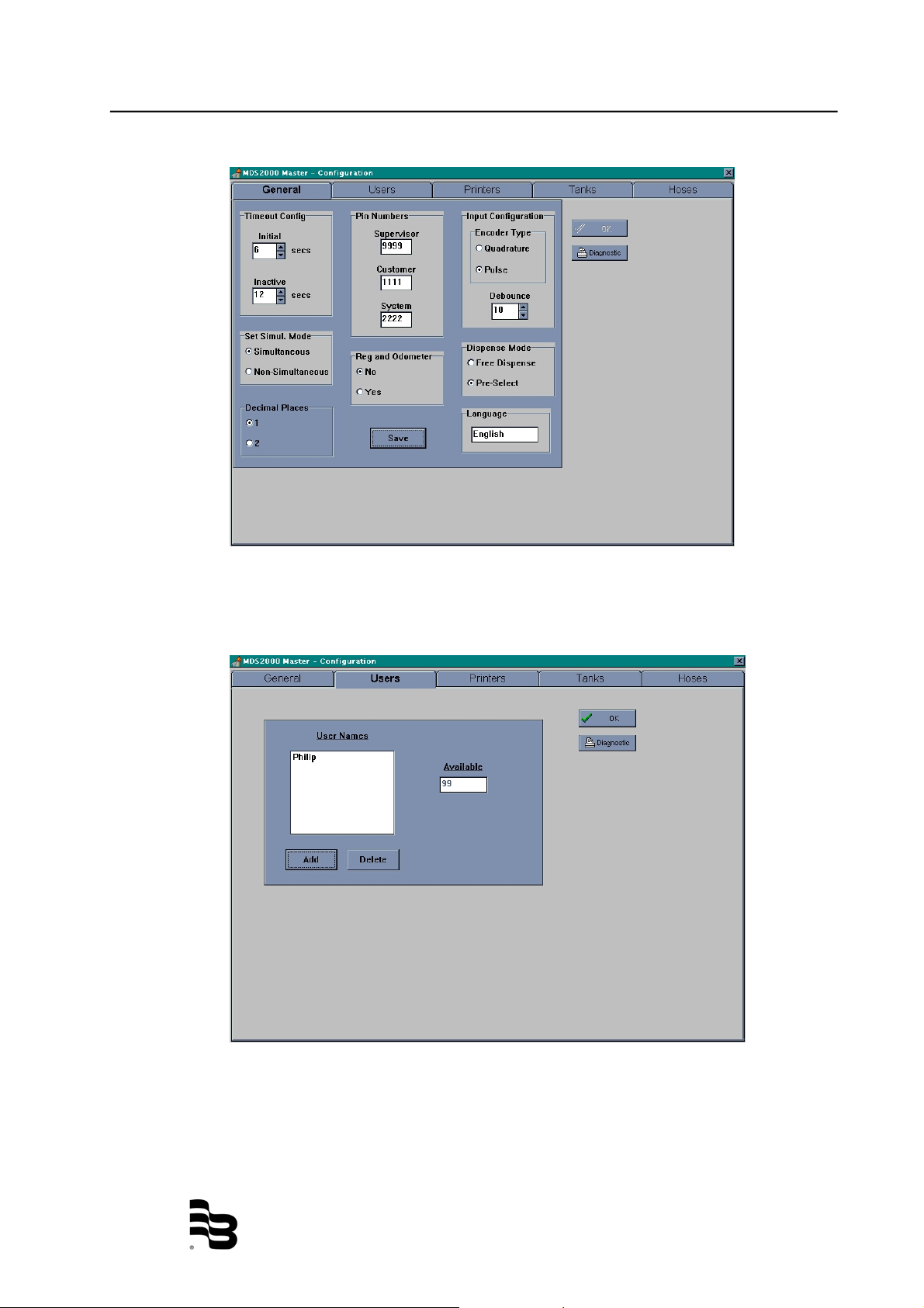
2.3.1 Configuration button
Click on it and enter your PIN number (different PIN numbers for three
levels of security: supervisor 9999 – system 1111 – configuration
2222).
You must configure all the MDS 2000 installation from the
PC. The PC software doesn't recognise the previous
configuration made at the keypad.
General:
From there, you can configure the different codes, times and general
configuration of the installation.
Click on the "change" buttons to get enable the windows button and
when all the changes are done, click the "save" button to save the
configuration.
LM_MDS2000_BA_02_0810
Page 35
Using the software Page 32/44
Users:
You can configure the names and codes of the different users of the system
to add a new user, click the "add" button and follow the steps on the screen.
LM_MDS2000_BA_02_0810
Page 36

Using the software Page 33/44
Printers:
You can configure the allocation of the different printers located in the
system.
First select the ID number of the I/O (o-7). Then choose where you want the
print reports and transactions from each keypad.
If you have a PC printer, also select where it is located.
Examples:
- Select I/O 0
- I/0 0 will communicate with keypad 0 to 7 only, and with the PC.
- Select the location of the report printer if you have a report printer
connected to a keypad or an I/O unit (remark: only the report requested
at the keypad are concerned, not the reports at the PC)
- Select the location of the ticket A, if desired, the location of a copy (ticket
B)
PC ticket:
The MDS 2000 allows to print the transaction ticket at the PC station, select
the COM or Parallel port where the transaction must be addressed.
Tanks:
Configure the product names and allocate them to the respective tank.
Click on the "add" button and follow the steps to create a new product.
LM_MDS2000_BA_02_0810
Page 37

Using the software Page 34/44
Hose configuration:
Allocate your hose outlets to the respective tank and the respective display
ID Nr.
For each selected I/O, enter the hose, tank and display allocation, the
correction factor, the PPl and the max. quantity to be dispensed at this
outlet.
Then click "save" to save your configuration.
(for more information, see "user manual" point 4: "system menu")
LM_MDS2000_BA_02_0810
Page 38

Using the software Page 35/44
2.3.2. Display button
Click on the display button and enter the system PIN number.
Two different buttons appear: - Tank level
- Oil usage
The oil usage button is for statistics by users and by products. It is not
available for this moment.
Click on "Tank status"
Click on a tank to configure it.
LM_MDS2000_BA_02_0810
Page 39
Using the software Page 36/44
How to proceed:
- The stock level may be in lts or gallons
- The tank size may also be in lts or gallons
- The warning level: when the stock arrives under the warning level, a
message will be printed on each transaction ticket and displayed on the
keypad when the corresponding hoses are required
- The stop level: it will prevent dispenses of the selected product when the
level in the tank is under the stop level limit. This will prevent air to enter
the oil line and prevent any risk of impurities entering the line as well
To change any values, just click on it!
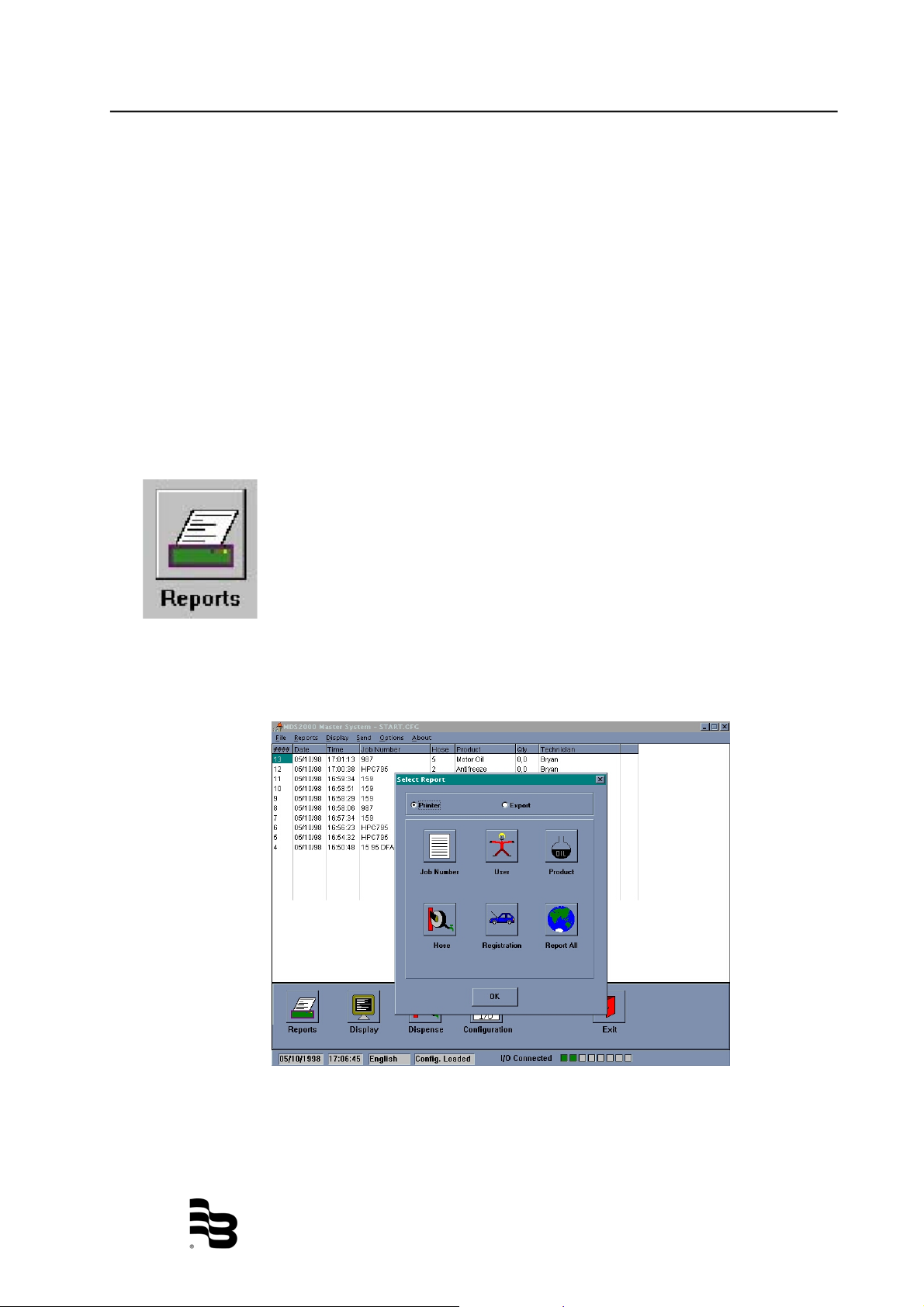
2.3.3 Report button
Click on the report button and enter the system PIN number.
Different types of transaction reporting are available:
- Report all: No selection, you receive all information
- Report by user: You can select the user with scroll menu
- Report by product: You can select the product with scroll menu
- Report by hose: Type the hose number
- Report by registration: Type the registration number
- Report by job number: Type the right job number
For each report you will have to select a date: from... to...
LM_MDS2000_BA_02_0810
Page 40
Using the software Page 37/44
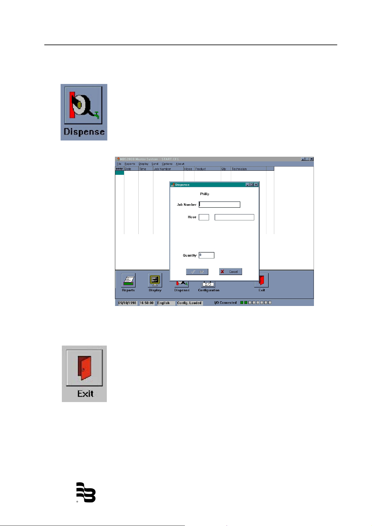
2.3.4 Dispense button
Click on the dispense button.
You use the PC like a standard keypad to make a transaction. If the
registration and odometer option is on, it will also appear on this
screen.
2.3.5. Exit button
Just click and you are out of the program.
On the top of the menu bar, the two needed items are the options:
SEND & OPTIONS.
If you activate the option SEND, the configuration stored in the
memory of your PC will be transferred on the MDS 2000 network.
To be used carefully:
The OPTIONS choice allows you:
LM_MDS2000_BA_02_0810
Page 41

Using the software Page 38/44
1. To change the language of the PC master software.
2. To enable or disable the sound- each time a transaction arrives on
the PC hard disk through the MDS 2000 network sound can be
heard.
To activate "Transactions to disk" which allows you to transfer a
copy of each transaction in a ASCII file on your hard disk. Each
ASCII file can be treated by any software program (such Excel –
Word – et. or into accounting package software).
You will need a special procedure to get this option enabled or
disabled.
Please contact your installer.
2.4. Export file possibilities
2.4.1 Two possibilities are available
#1.
On request of a transaction report (any available: by Job – Registration –
Hose – User – etc.), you have the choice between "Printer" or "Export".
If you choose "Export", an ASCII file will be issued (you have the choice
where to place this file). This file is an ASCII file (CSV format) and it is
exactly the same as a report issued in standard on the MDS system.
This option is more used for occasional applications (to make "spreadsheet"
report). For daily applications, we deeply recommend the 2nd possibility.
#2.
The "Transaction to disk" option is activated. Each time a transaction is
terminated and arrived on the screen of the PC, a "copy" is written on the
hard disk (or floppy, the place where to copy the file needs to be specified at
the activation of the option).
The transaction's copy is an ASCII file (CSV format).
2.4.2 Transaction to disk option
2.4.2.1 How is it working?
- Enter the code *** (special procedure)
- Select where you want to place the transaction to disk and
define the file
- The file is composed with 16 lines.
For each line select the information you want (select the line,
double click on the required information)
- As last operation, you have to put "End of File" to close the
procedure
LM_MDS2000_BA_02_0810
Page 42

Export file possibilities Page 39/44
2.4.2.2 General description
The PC is collecting information from the system, processing and
sending the data on a transaction base. The PC is responsible for
delivering an ASCII File in a local or shared file system in the
customer's computer transfer area, by means of different
techniques (or via Lanmanager or FTP, in a network environment,
via RS 232 in non networked environments, via local hard disk, or
even diskettes may be possible for emergencies). The customer
should then from this area, read and merge data into his own
software.
2.4.2.3 Transactions
The PC delivers each transaction in separate files named
"transaction nr.".
Each transaction possesses an unique number and so, one
transaction is equal to one ASCII file. The numeration is growing
from transaction n° "0" to "9999" after the numeration returns to
"0" and begins again until "9999".
The transaction is available no later than 1 minute after the
transaction has been terminated in the workshop.
LM_MDS2000_BA_02_0810
Page 43

Export file possibilities Page 40/44
2.4.2.4 Responsibility
It is the responsibility of the MDS to deliver secured transactions
in the DOS file system. It is the responsibility of the customer to
pick or to move datas from this area and to remove or to merge
transactions when used.
2.4.2.5 Security
The master software secures that each use of the system,
generates a transaction. This transaction should then be ready by
the customer and controlled for:
Correct Sequence n°:
If sequence n°s are missing, the customer's software should
generate a warning.
Action: a. Find the missing transactions and enter it manually
b. Search reason for missing transaction and correct
Correct Job n°:
If job n°s are not recognized, the customer's software should
generate a warning.
Action: a. Find the right job n° and enter it manually
b. Search reason for wrong job n° and correct
Correct Part n°:
If part n°s are not recognized, the customer's software should
generate a warning.
Action: a. Find the part n° and enter it manually
b. Change part n° in the PC software or in the
customer's software so they match.
LM_MDS2000_BA_02_0810
Page 44
Backup – restore or Archive Database Page 41/44
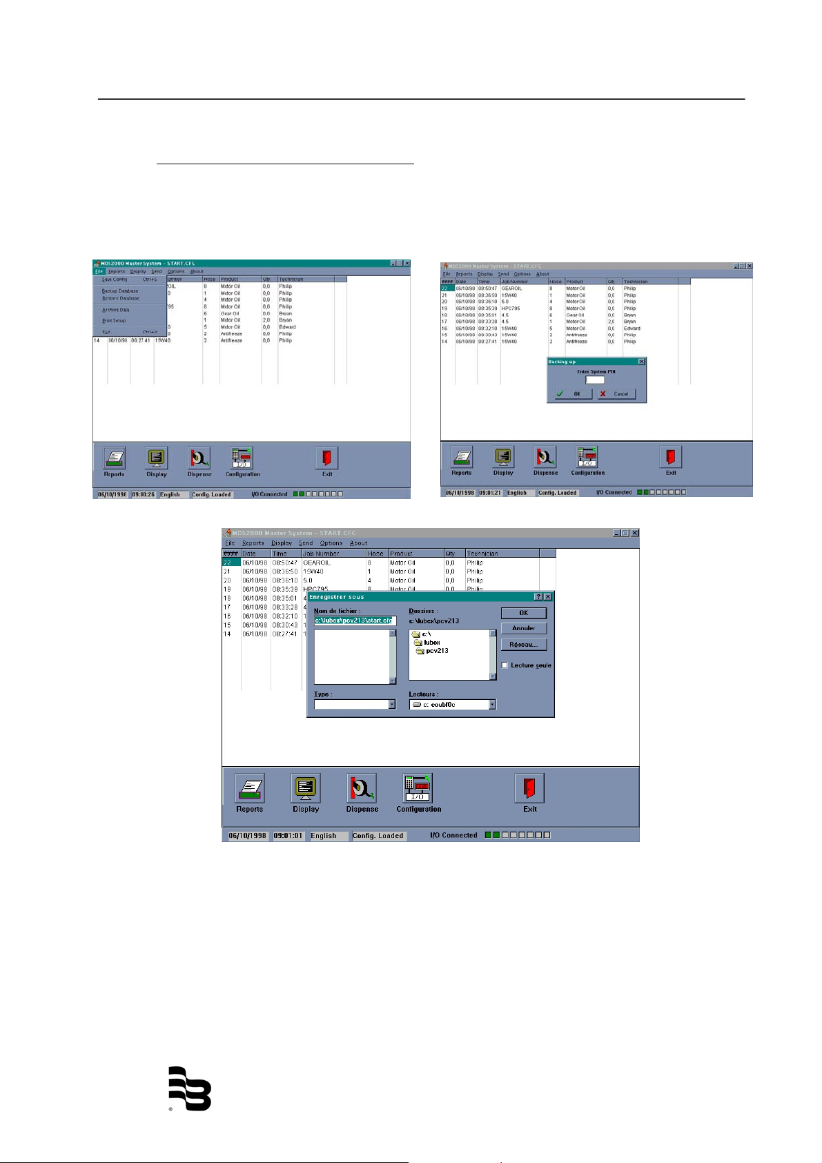
2.5. Backup - restore or Archive Database
You have first the possibility to backup the database you are using. You have to go
into the top menu bar in the "file"\Backup Database.
Enter the system PIN number and choose where you want to make your backup.
LM_MDS2000_BA_02_0810
Page 45
Backup – restore or Archive Database Page 42/44
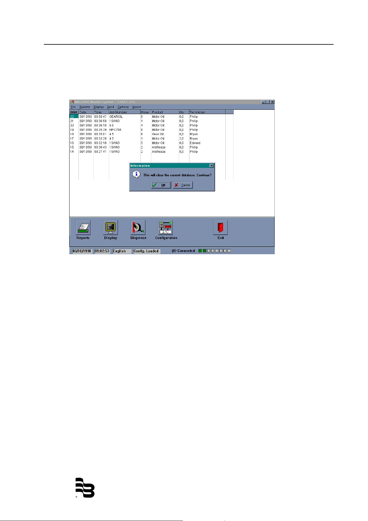
The second possibility you have is to restore a database.
Follow the same step as for the backup, the system will tell you that this will clear
the current database.
You can also archive your database. Follow the same procedure as to backup.
LM_MDS2000_BA_02_0810
Page 46

Manufacturer´s declaration Page 43/44
3. Manufacturer´s declaration
LM_MDS2000_BA_02_0810
Page 47

Warranty / DIN ISO certificate Page 44/44
4. Warranty
Badger Meter warrants meters and parts manufactured by it and supplied hereunder to be
free from defects in materials and workmanship for a period of 18 months from date of
shipment or 12 months from date of installation, whichever period shall be shorter. If
within such period any meters or parts shall be proved to Seller´s satisfaction to be
defective, such meters or parts shall be repaired or replaced at Seller´s option. Seller´s
obligation hereunder shall be limited to such repair and replacement and shall be
conditioned upon Seller´s receiving written notice of any alleged defect within 10 days
after its discovery and, at Seller´s option, return of such meters or parts to Seller, f.o.b. its
factory. THE FOREGOING WARRANTY IS EXCLUSIVE AND IN LIEU OF ALL OTHER
EXPRESS OR IMPLIED WARRANTIES WHATSOEVER INCLUDING BUT NOT LIMITED
TO IMPLIED WARRANTIES (EXCEPT OF TITLE) OF MERCHANTABILITY AND
FITNESS FOR A PARTICULAR PURPOSE. Badger Meter shall not be liable for any
defects attributable to acts or omissions of others after shipment, nor any consequential,
incidental or contigent damage whatsoever.
5. DIN ISO certificate
LM_MDS2000_BA_02_0810
Page 48

Hotline
Please contact your supplier for any technical assistance you may need.
®
Badger Meter Europa GmbH
Subsidiary of Badger Meter, Inc., USA
 Loading...