

Page 1
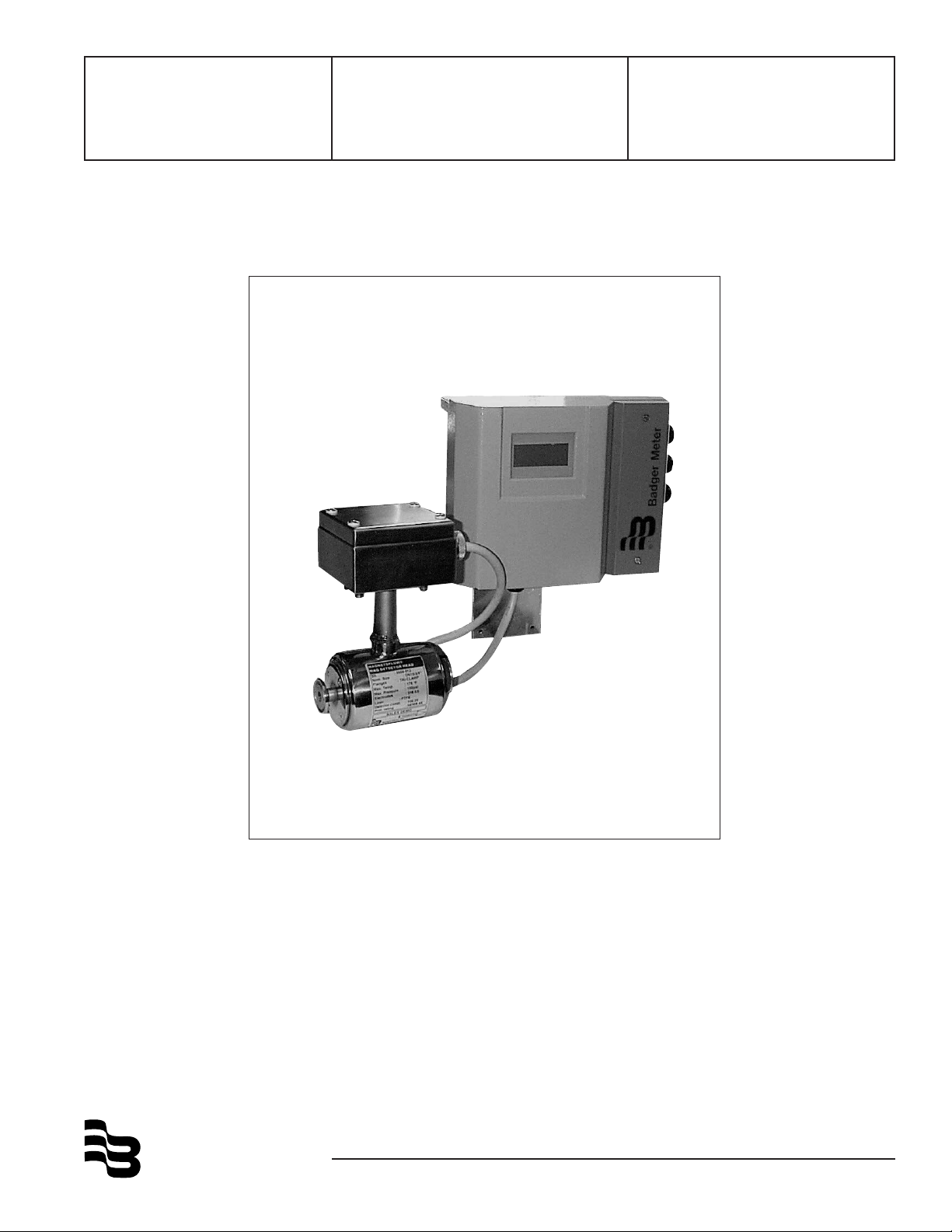
Magnetoflow
Mag Meter
®
Sanitary Meter
with Model Primo
®
3.1
Installation &
Operation Manual
IOM-104-02
BadgerMeter,Inc.
®
53400-104
3-09
Page 2
SCOPE OF THIS MANUAL
This manual contains information concerning the installation, operation and maintenance of Badger’s Magnetoflow
meter models with Primo® Amplifier.
To ensure proper meter performance, the instructions given in this
manual should be thoroughly understood. Keep a copy of this manual
in a readily accessible location for future reference.
®
electromagnetic flow
TABLE OF CONTENTS
System Description ........................................................................ 2
Unpacking and Inspection ............................................................. 2
Transportation and Handling ......................................................... 2
Meter Installation ............................................................................ 3
Specifications - Detector ............................................................... 5
Grounding ....................................................................................... 6
Specifications - Amplifier ................................................................ 6
Wiring .............................................................................................. 7
Programming ................................................................................... 9
Unit of Measure .......................................................................... 9
Full Scale Setting (Maximum Flow) ......................................... 10
Low Flow Cutoff ........................................................................ 10
Empty Pipe Detection ............................................................... 11
Flow Direction ........................................................................... 11
Filter Dampening ...................................................................... 12
Error List (Messages) .............................................................. 12
Resetting of Totalizers ............................................................. 12
Analog Outputs ......................................................................... 13
Pulse Outputs ........................................................................... 14
Wiring of AMR unit to Mag ....................................................... 14
Frequency Output .................................................................... 15
Flow Alarms .............................................................................. 15
Detector Factor Field Calibration ............................................ 15
Accuracy Test .......................................................................... 16
Meter/Pipe Size ........................................................................ 16
Password Protection ................................................................ 16
Language Selection ...................................................................... 16
Troubleshooting ............................................................................ 17
Error Message Explanation ......................................................... 18
Board Assembly Replacement .................................................... 19
Fuse Replacement ....................................................................... 19
All Badger’s Magnetoflow mag flow meters are factory tested and
calibrated. A calibration certificate is included in the shipment of each
meter.
UNPACKING AND INSPECTION
Magnetoflow mag flowmeters are shipped in special shipping containers. Upon receipt of the meter, perform the following unpacking
and inspection procedures. If damage to the shipping container is
evident, be present when the meter is unpacked.
A) Carefully open the shipping container following any instruc-
tions that may be marked on the exterior. Remove all
cushioning material surrounding the meter.
B) Retain the shipping box and all packing materials for possible
use in reshipment or storage.
C) Visually inspect the meter for any physical damage such as
scratches, loose or broken parts, or any other sign of damage
that may have occurred during shipment.
NOTE: If damage is found, request an inspection report by
the carrier’s agent within 48 hours of delivery. Then file a
claim with the carrier. A formal claim for equipment
damaged in transit is the responsibility of the customer.
D) Verify that the meter received is consistent with the product
ordered. The detail on the product labels on the detector and
the amplifier should help this verification.
E) All detectors with PTFE liner are shipped from the factory with
a liner protector. This protector maintains the proper form of the
PTFE material and protects it during shipping and storage. Do
not remove this protector until you are ready to install the unit.
F) Storage: If the meter is not to be immediately installed, store
it in its original container in a dry, sheltered location. Storage
temperature: -4 to 158 °F (-20 to 70 °C)
METER INSTALLATION
METER LOCATION GUIDELINES
The following are several guidelines for determination of a good
location for meter installation:
SYSTEM DESCRIPTION
Magnetoflow® electromagnetic flow meters are intended for fluid
metering in most industries including water, wastewater, food and
beverage, pharmaceutical and chemical.
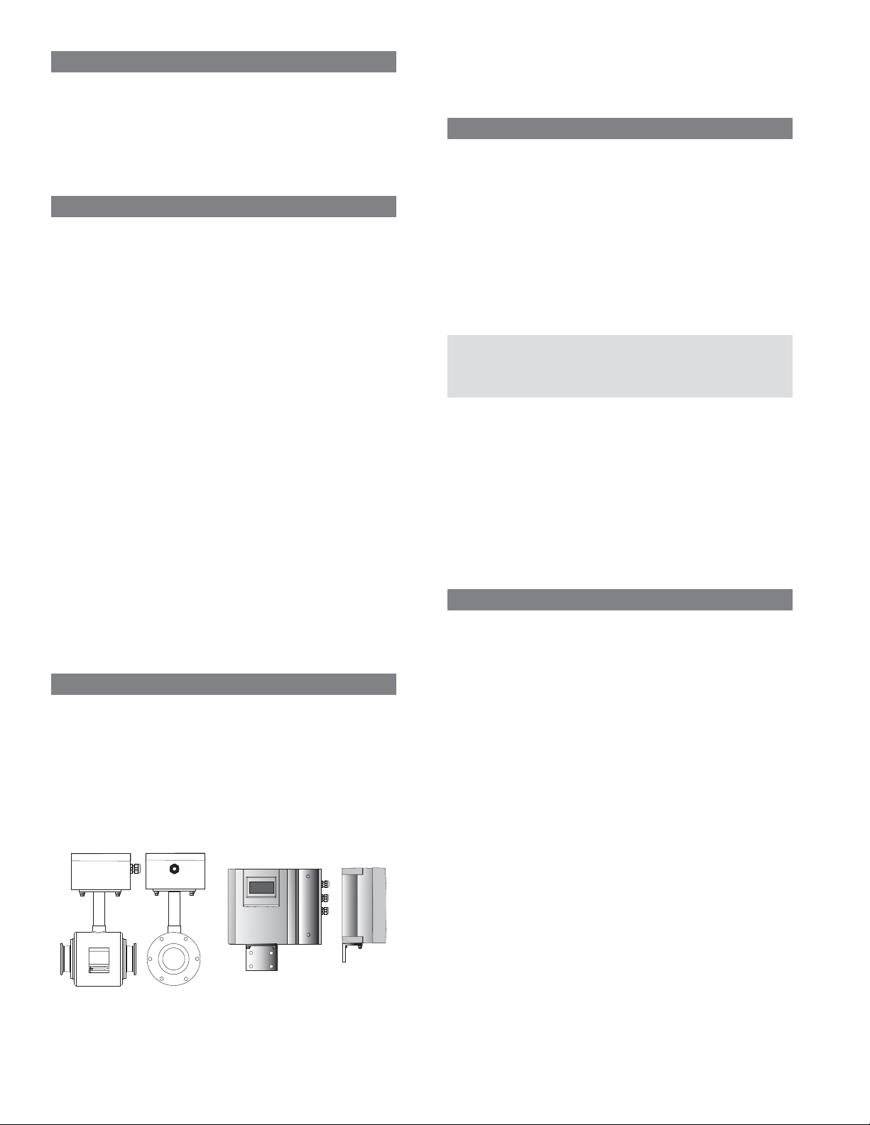
The basic components of an electromagnetic flow meter are two: 1)
The Detector; which includes the flow tube, isolating liner and
measuring electrodes, and 2) the Amplifier, which is the electronic
device responsible for the signal processing, flow calculation, display
and output signals.
Detector
The materials of construction of the wetted parts (liner and electrodes) should be appropriate for the specifications on the intended
type of service. Review of the compatibilities consistent with the
specifications is recommended.
Primo
Temperature Ranges
In order to prevent damage to the meter, the maximum temperature
ranges must be observed.
Primo® Amplifier
Ambient temperature: -4 to 140°F (-20 up to +60°C)
Detector
Fluid temperature: -40 to 311°F (-40 up to +155°C)
Outdoor Installations - Primo Amplifier
The Primo Amplifier can be installed outdoors but with a few
requirements:
1. The ambient environment must not be out of the temperature
ratings for the unit. (-4 to 140 degrees F)
2. The Primo must be protected to some degree from the outside
elements. At a minimum, a roof or shield of sorts should be
fabricated over the unit to protect the LCD display from the
sunlight. It will also keep the unit out of the possibility of a hard
sustained rain which could cause moisture to get into the unit. An
alternative approach would be to simply mount the unit in a
“Hoffman style” outdoor enclosure, eliminating the potential of
either issue arising.
If an indoor environment is within 250 feet of the Mag meter
installation, consideration should be given to increase the cable
length and mount the Primo indoors.
2
Page 3
Chemical Injection Applications
For water line applications with a chemical injection point, the meter
should be installed upstream of the chemical injection point to
eliminate any issues with the meter performance. If an upstream
location is not possible for the meter, consider moving the injection
point downstream of the meter location. If the meter must be installed
downstream of the chemical injection point, the distance between
these (2) locations must be significant; frequently 50 - 100 feet.
When the solution made up of the water and the injected chemical
reach the Mag meter, it must be a complete homogeneous mixture.
If too close, the Mag meter will sense (2) different liquids (conductivity
different for each) and will be confused as to how to process the
information. Many other factors such as the type of injection method,
(spaced bursts versus continuous stream of drops), or whether the
chemical is injected in a liquid or gas form, can cause a wide variation
in the distance required from one application to another.
Due to this wide range of factors, it is difficult to specify a distance that
will always work for any application without establishing a value far in
excess of what would usually be required. Please contact Badger
Meter's Technical Support at 1-800-616-3837 with your application
detail and they can assist in determining if the Mag meter should
properly perform. As noted, the meter may require 50 - 100 feet from
the injection point to assure the complete homogeneous state.
Submersible Option
If the meter is to be installed in a meter vault, it should be installed to
be sure the amplifier is not inside the vault.
Other Considerations
Avoid all pipe locations where the flow is pulsating, such as in the outlet
side of piston or diaphragm pumps.
Avoid locations near equipment producing electrical interference
such as electric motors, transformers, variable frequency, etc.
Install the meter with enough room for future access for maintenance
purposes.
The mag meter isolating liner is not intended to be used as gasket
material. Standard gaskets (not provided) should be installed to ensure
a proper hydraulic seal. When installing the gaskets, make sure they are
properly centered to avoid flow restriction or turbulence. Do not use
graphite or any electrically conductive sealing compound to hold the
gaskets in place during installation. This could affect the reading
accuracy of the measuring signal.
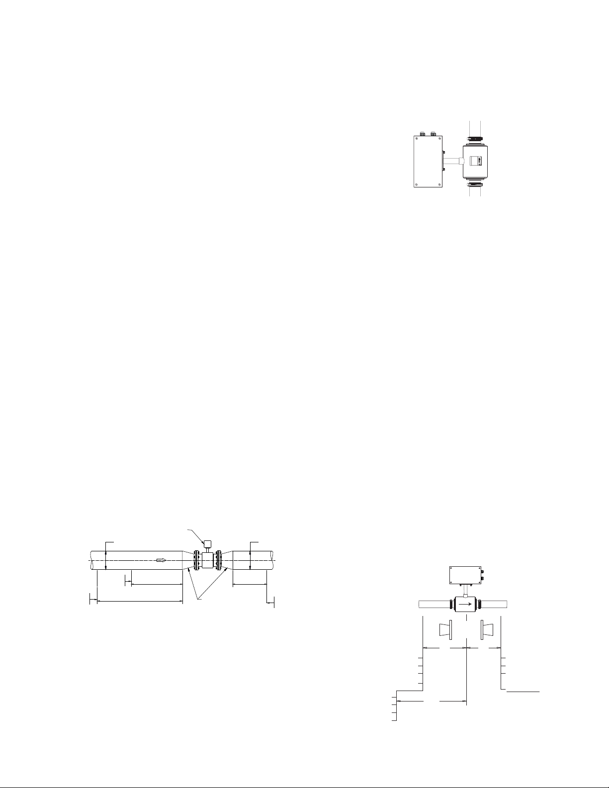
STRAIGHT PIPE REQUIREMENTS
For optimum accuracy performance, it is required to provide sufficient inlet and outlet straight pipe runs. An equivalent to 3 diameters
of straight pipe is required on the inlet side, and 2 diameters on the
outlet side. There are no special requirements for standard concentric pipe reducers.
MAGNETOFLOW MAG FLOWMETER
D (Pipe Size)D (Pipe Size)
FORWARD FLOW
chines, etc. Be sure both ends of signal cable are securely fastened.
Run power and signal cables in separate conduit.
METER ORIENTATION
Magnetoflow Mag Meters can operate accurately in any pipe line
orientation.
However, the most recommended installation position is vertical
piping, with the the liquid flowing upward.
FIG. 1 VERTICAL PIPE MOUNTING
HIGHLY RECOMMENDED
This installation practice ensures two objectives:
· The pipe remains completely full of liquid, even at low flow, low
pressure applications with a discharge to the atmosphere.
· Solid build-ups or sediments that could be part of the process
fluid will not deposit or accumulate on the liner and/or electrodes.
The model Magnetoflow® Sanitary meter is designed to measure flow
in bi-direction only. Carefully observe the "forward flow" label
attached to the meter body and install the meter accordingly.
PIPING CONFIGURATION
Appropriate piping arrangements should be provided to ensure
the meter is not exposed to extreme pipe vibrations. The piping
arrangements should include appropriate pipe supports.
For optimum accuracy performance, it is required to provide
sufficient inlet and outlet straight pipe runs. An equivalent of 3
diameters of straight pipe is required on the inlet side of the
meter, and 2 diameters on the outlet side, measured from the
center of the meter body.
Avoid installing the detector close to flow disturbance generating
valves and fittings.
Do not install the detector in the outlet side of Piston or
Diaphragm type pumps. Avoid all pipe locations where the flow is
pulsating. Avoid installing the detector in the suction side of any
pumps; possible creation of vacuum can affect meter
performance or cause damage to the PTFE liner.
TEMPERATURE
Note: Environmental temperature of installation is not to exceed
maximum specification of 122°F (50°) for the Primo amplifier.
ELBOW
CHECK VALVE
GLOBE VALVE
BUTTERFLY VALVE
PUMP
TEE
GATE VALVE
(FULLY OPEN)
MINIMUM STRAIGHT PIPE
3 x D
MINIMUM STRAIGHT PIPE
7 x D
MINIMUM STRAIGHT PIPE
STANDARD CONCENTRIC
REDUCERS
(NO DISTANCE REQUIRED)
2 x D
ELBOW
TEE
ANY VALVE
By using pipe reducers, a smaller meter size can be mounted in larger
pipeline sizes. This may also increase low flow accuracy performace.
In order to minimize flow disturbances and excessive loss of head,
custom fabricated pipe reducers must have a minimum slope angle
of 15 degrees. If this is not possible, install the custom pipe reducers
as if they were fittings, leaving the minimum straight pipe required.
Mounting Location
The detector should never be installed on the suction side of a pump
where a vaccuum exists to eliminate the possibility of damage to the liner.
If vibration exits on the pipeline, secure the piping before and after
the meter. If a strong vibration exists, the amplifier should be mounted
remotely. Do not install cables near power cables, electrical ma-
GLOBE VALVE
NEEDLE VALVE
CHECK VALVE
PUMP
ELBOW
GATE VALVE
(FULLY OPENED)
BALL VALVE
UPSTREAM
TEE
5-7 D
STRAIGHT PIPE RUN
(ANY POSITION)
PIPE REDUCERS
NO REQUIREMENT
DOWN STREAM
2 D3 D
ELBOW
TEE
ANY VALVE
NO PUMPS
3
Page 4
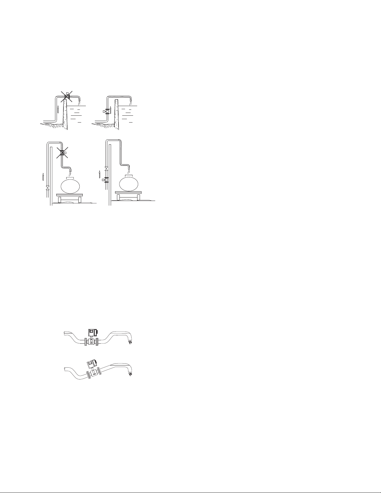
PARTIALLY FILLED PIPE SITUATIONS
FLOW
FLOW
FLOW
FLOW
Magnetoflow® mag meters are designed to operate in closed, full
pipes.
It is relatively common to encounter situations where the process
pipe will remain momentarily partially filled due to certain hydraulic
conditions. Examples of this include discharge to the atmosphere
(lack of back pressure), insufficient line pressure, gravity flow
applications, etc.
WRONG
FLOW
WRONG
FLOW
RIGHT
FLOW
RIGHT
FLOW
To eliminate the negative effect of these situations on the
performance of the mag meter, observe the following guidelines:
· Avoid installing the detector in the highest point of the pipe line
· Do not install the detector in vertical, downward flow sections
of the pipe
· ON/OFF valves should ALWAYS be located on the downstream
side of the meter
· Select the recommended vertical orientation with flow upwards
whenever possible
· Make sure that the flow range of the meter size selected is
consistent with the application flow range
To minimize the possibility of partially full pipe flows in horizontal,
gravity or low pressure applications, it is recommended to create a
pipe arrangement as shown in the figure below. This arrangement
ensures the detector remains full of liquid at all times.
Open Discharge
Horizontal Installation
Open Discharge
Horizontal
4
Page 5

3.94"
3.94"
Meter with junction box for
®
D
remote Primo
converter
B
A
C
Flow RangeEst. Weight
ABC Dwith Primo GPM LPM
inches mm inch mm inch mm inch mm inch mm Lbs Kg Min Max Min Max
3/8”10 7.1 180 .992 25.2 2.8 70 8.3 210 12 5.5 0.034 11.4 0.13 43
1/2”15 7.1 180 .992 25.2 2.8 70 8.3 210 12 5.5 0.06 20 0.23 76
3/4”20 7.1 180 .992 25.2 2.8 70 8.3 210 12 5.5 0.13 45.4 0.52 171
1” 25 7.1 180 1.984 50.4 2.8 70 8.3 210 13 6 0.24 80 0.92 305
1 1/2” 40 7.9 200 1.984 50.4 3.5 89 9.3 235 15 7 0.6 181 2.1 687
2” 50 7.9 200 2.516 63.9 4.1 104 9.8 250 17 7.5 1.0 323 3.7 1223
2 1/2” 65 10.6 270 3.047 77.4 5.1 129 10.6 270 20 9 1.5 504 5.8 1910
3” 80 10.6 270 3.579 90.9 5.5 140 11.0 280 23 10.5 2.2 727 8.3 2751
4” 100 10.6 270 4.682 118.9 6.3 160 11.8 300 24 11 4.0 1292 14.8 4892
SPECIFICATIONS
Flow Range: 0.1 - 33 fps (0.03-10 m/s)
Sizes: 3/8" to 4" (10 to 100 mm)
Min. Conductivity:
Accuracy:
≥ 0.5% accuracy of rate from .1-1 fps.
≥ 0.25% accuracy of rate from 1-33 fps.
≥ 0.5 micromhos/cm
Electrode Material: Alloy C
Liner Material: PTFE
Max. Fluid Temperature: 311°F, (155°C)
Pressure Limits: 150 psi (10Bar)
Coil Power: Pulsed DC
Ambient Temperature: -4°F to 122°F, (-20°C to 50°C)
Meter Enclosure Material: Stainless Steel 316
End Connections: Tri-clamp (sizes 1"-4" per ISO 2852)
Junction Box Enclosure Protection: Stainless Steel, Nema 4X
Cable Entries: 1/2" NPT Cord Grip
Remote Amplifier Enclosure: NEMA 4
PRIMO® AMPLIFIER (3.1 ELECTRONICS)
11.7"
7.75"
298mm
197mm
SPECIFICATIONS
Power Supply: 85-265 VAC, 45-65 Hz
Power Consumption: 20W
Accuracy: ± 0.25% accuracy of rate from 1-39.4 fps.
Repeatability: 0.1%
Minimum Fluid Conductivity: 5.0 micromhos/cm
Flow Direction: Unidirectional or bidirectional, 2 separate
totalizers (programmable)
Analog Outputs: 0/4-20mA, 800ohms Max Load
Ouput Frequency: Scaled Pulse output, (open collector) Max
5Khz
Digital Outputs:
Voltage sourcing transistor, 24VDC, 100mA max
(3) AC electro-mechanical relays, 48VAC, 0.5 amp max
± 0.5% accuracy of rate from 0.1-1.0 fps.
9.68"
246mm
25mm
1"
4.96"
126mm
Mounting Bracket for
Remote Configuration
Outputs: All ouputs are short circuit safe
Noise Dampening: Programmable from 1 to 6
Pulse Width: Programmable up to 500ms
Galvanic Isolation: ≤ 500V
Zero-point Stability: Automatic correction
LCD Display: 4 lines x 16 character back-lit alphanumeric
Displays (2) Totalizers, Flow Rate, Alarm conditions
Housing: Cast aluminum, powder coated paint
Housing Rating: NEMA 4X
Mounting: Detector mount or remote mount (bracket supplied)
Cable Connection: 1/2" NPT Cord Grip
Ambient Temperature: -4 to 140° F (-20 to 60° C)
Serial Communication: RS232
5
Page 6
WIRING
At installation, be sure to comply with the following requirements:
IMPORTANT!
• Disconnect power to the unit before attempting any
connection or service to the unit
• Do not bundle or route signal lines with power lines
• Keep all lines as short as possible
• Use twisted pair shielded wire for all output wiring
• Observe all applicable local electrical codes
For the AC power connections use three wire sheathed cable with
overall cable diameter of 0.2" to 0.45" (5mm to 12mm). For signal
output use 18 to 22 gauge (0.25 mm
Overall cable diameter between 0.12" to 0.35" (3mm to 9mm).
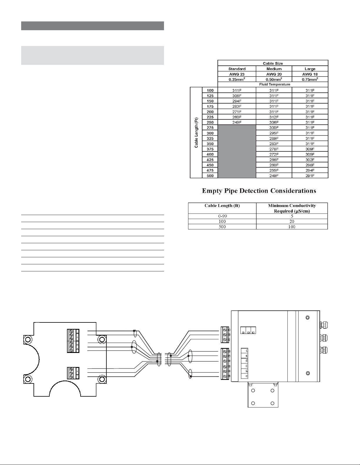
WIRING FOR REMOTE PRIMO® CONFIGURATION
Wiring between the detector and the Primo amplifier comes complete
from the factory. If your installation requires the use of conduit, the
following are recommended steps for wiring of the detector to the
amplifier.
1. Remove the junction box lid. Carefully remove the wires connected
to the terminal blocks that run to the Primo amplifier. Note which
wire goes into which terminal. The chart below may be of assistance for reference of wire color and terminal connection.
2. Run cable through conduit from Primo amplifier location, retaining
the wiring of the cable to the amplifier as supplied.
2
to 0.75mm2) shielded wire.
Remote style Primo Amplifier models can be ordered with longer
cable than our standard stock lengths of the standard cable; 15, 30,
50 and 100 feet. The following chart shows the cable style options
and the maximum flow medium temperature that can exist in the
application environment at a given length of that cable.
3. Complete conduit assembly on both ends and rewire cable into
junction box as wired when received. See wiring diagram below.
Connection No. Description Wire color
11 Coil Green
12 Coil Yellow
13 Main Shield Yellow/green
45 Electrode White
44* Electrode Shield Black
46 Electrode Brown
40 Empty Pipe Pink
44* Empty Pipe Shield Black
*Connections with the No. 44 are lying on the same potential
Wiring for Remote Primo Configuration
shield (black)
pink
brown
shield (black)
white
yellow/green
yellow
green
44
40
44
46
44
45
13
12
11
green
yellow
yellow/green
white
shield (black)
brown
pink
shield (black)
13 12 11
45
44
46
44
40
44
6
Page 7

WIRING INPUTS AND OUTPUTS TO THE PRIMO
®
AMPLIFIER
Once the wiring between the sensor and the amplifier is done proceed
to wire any inputs and outputs to the Primo amplifier.
IMPORTANT! For safety reasons leave AC power connections to the unit as the last step. Follow all the safety
precautions and local code to prevent electrical shock and/
or damaging of the electronic components.
1. Loosen the two bolts on the red amplifier cover. Remove the cover.
Inside the amplifier you will see a terminal strip similar to the one
depicted in the figure to the right.
POWER
To prevent accidents, power connection should be made only
after all other connections have been completed.
The PRIMO amplifier is a microprocessor based device. It is
important that the power supply be as "clean" as possible.
Avoid using power lines that feed heavy loads such as pumps,
motors, etc. If dedicated lines are not available, a filtering or isolation
system might be required.
It is recommended that the internal fuse protection be maintained.
Use a 2 amp slow blow fuse.
Board Accessible with Red Cover Removed
Line
How to connect the amplifier to remote digital indicators/
totalizers that do not require external power supply
This connection is intended for use with indicators that do not require
an external power supply such as the ER series indicators from
Badger Meter. For the ER-6, ER-8 or ER-9, connect terminal 15 of
the Amplifier to terminal 2 of the ER series and terminal 16 to ground
or terminal 1 of the ER indicator.
For connection to the PC 100 Controller, connect terminal 15 of the
amplifier to terminal 14 of the PC 100 and terminal 16 of the amplifier
to terminal 12 of the PC 100.
Pulse Output Passive (+)
Pulse Output Active
(+24vdc)
Flow Direction Common
Error Out
(Open if error occurs)
Flow Alarm (Open between
min. and max. values)
Frequency Output
Emitter (-)
Active Analog Output (+)
Analog Common (-)
15
13
11
9
7
5
3
1
16
14
12
10
8
6
4
2
Pulse Output Common (-)
Reset (-)
Reset (+) (open to reset)
Forward Flow Direction
Reverse Flow Direction
Error Out Common
Flow Alarm Common
Frequency Output
Collector (+)
RS 232 TxD
RS 232 RxD
RS 232 Ground
7
Page 8

PROGRAMMING (3.1 Electronics)
The Primo® amplifier comes preprogrammed from the factory and in
most instances will not require any additional manipulation. However,
if you will be using the flow signal outputs or need to reprogram the
meter to suit your particular needs, it will be necessary to familiarize
yourself with the programming procedures.
Programming of the Primo amplifier is very simple
This section gives step by step instruction on how to program each
of the functions of the amplifier and an explanation of the choices that
are available for each one.
First, using a small flat screwdriver, remove the red cover from the
main amplifier housing. At the lower right corner of the unit you will
see three square buttons. These buttons are used to perform all
programming procedures.
Programming Keys
NOTE: The programming buttons have been placed inside
the amplifier enclosure to prevent tampering or accidental
reprogramming of the unit. After programming, be sure to
reassemble the red cover on the enclosure.
The four line 16 digit LCD display of the Primo amplifier will guide you
through each of the programming options/steps. The main screen will
display:
1st Line: Flow Rate
2nd Line: Totalizer (TOT+ or TOT1)
3rd Line: Totalizer (TOT- or TOT2)
4th Line: Displays revision of software to assist
in troubleshooting. This line is also
used to display any error messages
that may occur during operation of the meter.
The main display screen will be in one of the following modes. (See
Flow Direction on page 11 for additional detail.)
the programming parameters, the program returns automatically to
the main screen. Even during the parameter setting mode, the meter
will be measuring and totalizing any flow that occurs.
There are three main submenus: factors, outputs/totals and measurement. Each submenu gives access to the following appropriate
functions:
Factors:
1) Detector factor
2) Pipe diameter
3) Password protection
Outputs/Totals:
1) Reset totals
2) Analog outputs
3) Pulse outputs
4) Frequency
5) Flow alarm
Measurement:
1) Unit
2) Full scale
3) Low flow cutoff
4) Empty pipe detection
5) Flow direction
6) Filter
7) Error list
PROGRAMMING OF MEASUREMENT
PARAMETERS
When the programming submenu screen appears, notice the right
arrow on the far left side. Using the up arrow key, you can position
the arrow in front of the submenu that you wish to interrogate. We
recommend starting with the "measurement" submenu followed by
the "outputs/totals" submenu and finally the "factors" submenu.
Uni-Directional Mode
Bi-Directional Mode
By pressing the Enter or E key (bottom key), you will be at the main
submenu screen. If no entry is done within 5 minutes while in any of
Use the key to position the > arrow next to "measurement" and
press the key. The following screen will appear:
UNIT OF MEASURE
This is where you will select the unit of measurement for the flow rate
indication and the totalizers. Use the key to place the arrow next
8
Page 9

to "change" and press key. The first unit of measurement screen
will appear:
applications requirements, making sure that it falls within the suggested flow range of the meter.
Using the or keys,select the desired unit of measure for flow rate
indication.
Choices are:
L/h Liters/hour
L/m Liters/minute
l/s Liters/second
m³/h Cubic meters/hour
m³/m Cubic meters/minute
m³/s Cubic meters/second
GPM US gallons/minute
MGD US million gallons/day
LbM US liquid pounds/minute
oz US fluid ounces/minute
IGM Imperial gallons/minute
The existing totalizer values are automatically converted into the
selected unit of measure.
After selecting unit of measure for flow rate, press Enter. You will see
the following screen for selecting unit of measure for the totalizer.
When done, press enter and then the key and the next parameter
will appear.
This is the same full scale parameter as previously visited. It is
positioned here to provide ability to change full scale setting if no unit
of measure change is necessary.
The full scale can be chosen in a range of 0.4 up to 39.4 ft/sec. A flow
value is assigned to the analog output as well as the frequency output
by the full scale scaling. The scaling is valid for both flow directions.
NOTE: If the flow rate is exceeding the full scale setting by more
than 5%, an error is indicated that the selected full scale range
is exceeded. (Terminals 7 and 8)
Once this is done, press E and then the key and the next parameter
will appear:
LOW FLOW CUTOFF
This is the low flow cutoff function. It is used to assign a low flow rate
at which measurement will stop, preventing measurement and thus
totalization errors. This parameter can be programmed from 0 % up
to 10% of selected full scale flow rate.
Choices are as follow; any existing values on the totalizers will
automatically be converted into the new selected unit of measure
L Liter
m³ Cubic meter
G US gallons
MG US million gallons
Lb US liquid pounds
oz US fluid ounces
IG Imperial gallons
aft Acre feet
ft³ Cubic feet
After the totalizer unit of measure selection, press the E key the
following screen will appear:
FULL SCALE (MAXIMUM FLOW)
If you changed the unit of measure, the full scale or maximum flow
may also need to be changed to reflect the maximum flow rate with
the new unit of measure. This is a very important parameter as it
relates to other parameters including frequency output, lowflow cut-off, alarm outputs and analog signal outputs. Adjust
the desired new full scale setting based on your meter size and your
Place the > arrow next to "change" and then press the key. The
following screen will appear:
The factory setting is 0.2%. Increasing this value will help prevent
false readings during "no flow" conditions due to fluid movement in
the pipe caused by vibrations or piping arrangements.
Using the and keys select a value and then press ENTER.
Press key and you will see the next parameter:
9
Page 10

EMPTY PIPE DETECTION
The empty pipe detection parameter when programmed to be ON will
provide an error relay indication if the meter is partially filled with liquid.
This will also show an empty pipe error message on the display.
Position the > next to "change" and press the key. The following
screen will appear:
NOTE: The empty pipe detection can be calibrated if required
if the fluid conductivity is different than water or the remote
cable length is significantly changed.
When calibration is complete, hit ENTER.
The switching threshold for the empty pipe detection is when the
measuring signal “full pipe” plus hysteresis value is exceeded (i.e.
= 360 mV+ 1000 mV). The maximum value for the switching threshold
is at 4000 mV.
If full pipe calibration value is higher than 3000mV, please contact
customer service for assistance.
Hit key for next parameter screen:
FLOW DIRECTION
The flow direction can be programmed to uni- or bi-directional modes.
Use the and keys to turn the feature ON or OFF as desired.
If off is selected, hit ENTER and then the key to go to the next
parameter. If ON is selected, hit ENTER and the following screen
will appear:
To proceed with calibration, leave "YES" selected and hit ENTER
for the next screen.
The pipe has to be filled with the media that will be measured by the
meter. A value between 0 and 5000 mV will be measured and
displayed. The value increases with decreasing conductivity,
increasing cable length or size. For normal water, the value should
be between 10mV and 500mV. Afterwards the signal difference
between full and empty pipe is determined by the hysteresis value.
Place the > next to "change" and press the key. One of the
following (2) screens will appear:
Uni-directional totalizes the flow only in one direction (flow direction
on the detector label). If the fluid is flowing in the opposite direction,
the counter will indicate zero on the display and no outputs. Both
totalizers can be used as resettable counters in this mode. The
totalizers are indicated as "TOT1" and "TOT2".
The bi-directional setting measures the flow in both directions. The
first totalizer (TOT+) is measuring in the forward flow direction and
the second totalizer (TOT-), the reverse direction. A change of flow
direction is indicated via the flow direction relay.
Make sure your pipe is full of fluid and when ready, hit ENTER. This
new screen is the hysteresis value entered. This value is set at the
factory at 1000 mV to allow some variation in empty pipe detection
to eliminate the potential for false "empty pipe signals." It is not
necessary for this value to be changed.
10
Page 11

Relay Wiring Terminals
Using the and key select which flow direction mode you want
and press ENTER. Hit the key to go to the next parameter.
FILTER DAMPENING
This feature is for dampening of all output signals and flow rate
display. This function has no effect on the totalizers.
The factory setting is 1. If you notice too much back and forth
oscillation of the flow rate indication, increase this value incrementally until the display is more stable. Your choices are 1 though 6 or
"Inactive." To change the filter value, place the arrow next to "change"
and press the key. The following screen will show:
Any error is indicated via the error relay as well as displayed on
line 4 of the LCD display. The relay is normally closed during
normal operation and is opened when an error occurs.
Error Relay
Now hit the key again and you will be at the screen for clearing
all the error list information.
Hit Enter to clear and the following screen will appear with "Done"
indication.
Using the and keys select the desired filter value and then
press ENTER. Hit key to go to last parameter of this submenu.
ERROR LIST (MESSAGES)
The error list in the program menu indicates the last 8 error types
that have occurred and the frequency of each. The sum of all
switching on processes can be read on the "Power Up Counter." This can assist in checking possible power failures.
Line up the > with "change" and hit the key. This will bring up
the 1st error. Continue hitting the key to toggle through the last
8 errors that occured, with #1 being the most recent error and the
power-up indication screens.
An overview of the possible errors and causes can be found in
the Troubleshooting section.
Now hit enter twice and you will be back at the submenu screen.
PROGRAMMING OF OUTPUTS/TOTALS
PARAMETERS
The next submenu is outputs/totals.
From the main submenu screen, position the > next to the "outputs/
totals" submenu and press the key.
The following screen will appear:
RESETTING OF TOTALIZERS
This parameter is used to reset either of the totalizers to zero.
11
Page 12

Line up the > with change and hit key.
Now line up the > next to the totalizer you wish to reset. Hit key and
that totalizer will now indicate "DONE."
If desired to reset the other totalizer, repeat the same steps.
Press or keys until you find the type of analog output that you
desire among the following screens:
The "TOT2" totalizer in the uni-directional flow mode, can be reset
externally.
The following is the wiring connections diagram for external reset.
When finished, hit Enter. Hit key to go to the next parameter.
ANALOG OUTPUTS
This parameter is for selection of the desired analog output and
also calibration if required.
The following are the options available for the analog output ranges.
NOTE: The flow value is limited to 105% of the programmed full
scale value. If this value is exceeded, an overflow error will appear
on the LCD display. In bi-direction operation, the flow direction is
indicated via the flow direction relay. The following diagram illustrates wire connections for the analog ouput signal.
Once you have selected the output, press the ENTER key to select
that particular output. You will then be at the calibration screen. You
should calibrate the analog output after you have it connected to your
PLC or chart recorder.
4 to 20 mA
0 to 20 mA
2 to 10 mA
0 to 10 mA
Press the key at the "change" line the following screen will appear:
12
Page 13

If calibration is in fact desired, hit ENTER again to get to the following
screen:
This is an important reminder to make sure that if the meter
is part of a closed loop system, you must put the system in
manual operation while performing the calibration process.
Hit the key to continue and this screen will apprear:
Hooking up an amp meter in series with the connected chart recorder
(Terminals 1 and 3), you may use the and keys to calibrate the
4mA signal for "0" flow. Hit ENTER to continue.
Use the and keys to change the value to the desired pulse rate.
This value may be set from .001 to 10,000 pulses/unit of measure.
Maximum frequency of 10kHz can not be exceeded. Based on
maximum flow rate setting, the program will not permit a value that
exceeds this frequency.
Press ENTER when you have programmed the desired number.
This parameter is pulse width, or the time duration that each pulse
will be "ON". The 50% setting means 50% on 50% off. You can set
the width in increments of 5 ms from 5-500 ms. The factory setting
is 20 ms. Program this parameter to match the required pulse width
of the remote accessory that will receive the pulse output. For output
to any AMR device, see steps below.
Now the 20 mA signal may be calibrated for 100% flow based on
maximum flow rate set in programming.
NOTE: When you use a different analog output setting than 420mA, (i.e. 0-20mA) that the output calibration will still be
performed with 4-20mA and applied to the selected setting (i.e.
0-20mA).
Hit ENTER to complete calibration and the key for next parameter.
PULSE OUTPUTS
The pulse output parameter will determine how many pulses per
gallon, liter, etc. will be sent out to remote counters, controllers, etc.
It will also set how many decimal digits will be displayed on the
totalizers. If, for example, you choose 100 pulses per gallon, then the
display totalizers will have two digits after the decimal point.
Move the > arrow next to "change", then press the key and the
following screen will appear:
Hit enter and the next screen is:
This parameter permits changing of the factory setting of "Normally
Open" for the pulse output to "Normally Closed." After complete, hit
enter and the key for the next parameter.
WIRING OF AMR UNIT TO MAG METER
AMR Wiring Diagram
Pulse Output
Passive
Pulse Output
Common
Primo Terminal
15
Primo Terminal
16
Step 1: Check to make sure your pulse output settings are correct
per chart.
Maximum Flow Rate Pulse Output Setting
Less than 5500 gpm 1 pulse per 100 or 1000 gallons
Greater than 5500 gpm 1 pulse per 1000 gallons
Less than 5500 Cu. Ft./min. 1 pulse per 100 or 1000 Cu. Ft.
Greater than 5500 Cu. Ft./min. 1 pulse per 1000 Cu. Ft.
Step 2: Set pulse width to "50 ms (AMR)"
Step 3: Set pulse type to "normally open"
Red (+)
Black (-)
AMR
Device
13
Page 14

The following diagram is for other wiring connections for pulse
outputs.
FREQUENCY OUTPUT
This is the Frequency Output parameter. The setting can range from
500 Hz up to 5000 Hz for the Full Scale Value. (Example: If 1600 Hz
is selected, then when meter display indicates full scale value, this
output is equal to 1600 Hz).
Use the and keys to select the minimum flow percentage and
press ENTER; the following screen will appear:
Use the and arrows to change the maximum flow percentage
and press ENTER.
NOTE: On the signal output, the relays will remain energized until the flow rate returns to within the flow limits.
Flow Alarm Relay
If a change is desired, line up > cursor with change and hit key.
When complete, hit Enter.
Hit key for next parameter.
FLOW ALARMS
This parameter allows the setting of a minimum and maximum
percentage (%) of the Full Scale flow rate value. Settings can be made
in 1% increments from 0 to 100%. The minimum value must be smaller
than the maximum value.
Press ENTER again to return to submenu screen.
PROGRAMMING OF FACTORS
PARAMETERS
The third and last submenu "Factors" contains parameters that
usually do not require changes.
Press ENTER until you reach the submenu screen if not already there.
Position the > next to the "factors" submenu and press the key.
The following screen will appear:
DETECTOR FACTOR (FIELD CALIBRATION)
This is the Detector factor setting. When the meter was calibrated,
this value was programmed in this parameter as a result of that
calibration. Each detector has its individual factor. This detector
factor is also included on the label of the meter body.
Move the > next to "change" and press the key. The following
screen will appear:
Line up the > with "change" and hit key. This is the detector factor setting.
14
Page 15

With this parameter, you can fine tune your calibration to meet your
applications needs. If you find that the meter is off by a certain percentage,
you can modify the detector factor to achieve the desired accuracy.
Even though all meters are calibrated at the factory, sometimes your
specific installation and fluid parameters make it necessary to
recalibrate a meter under actual operating conditions with the liquid
being metered.
The following instructions are provided to assist in performing an onsite calibration check and adjustment. This procedure may require
either a test tank or vessel of known capacity or a second flow meter
installed in the same line.
ACCURACY TEST
1. Place a test tank of calibrated volume at the output of the meter.
2. Operate meter until test tank is filled to the appropriate calibrated
level. Since meter accuracy can vary somewhat with flow rate,
we recommend making test run at the same flow rate used in
actual operation.
3. Record quantity indicated on display totalizer.
4. Repeat run three times and calculate an average for the (4) tests.
5. Perform the following calculation to determine the percent of
accuracy of the meter.
When complete, press Enter.
Hit key to go to the next parameter.
PASSWORD PROTECTION
This is the password protection parameter. The unit will be set at "0"
(no password required) from the factory. If activated, whenever you
want to go into any of the submenus, the unit will ask for the password number.
To activate the password, line up the > with "change" and hit key.
Qty. Delivered in vessel Old Detector New Detector
Average Meter Reading
Example 1.
In this example, the meter accuracy is low and must be increased
by a calibration correction.
Example 2.
In this example, the meter accuracy is high by 4% and must be
reduced by a calibration correction.
When finished with detector factor parameter, hit ENTER and then
hit key to go to the next parameter.
100 Gallons x
95 Gallons
100 Gallons
104 Gallons
x
Factor
68.85 = 72.47
x 68.85 = 66.20
=
Factor
METER/PIPE SIZE
Change "0" to any desired number from 1 to 999. Hit enter and after
returning to the main screen, you will always have to enter the new
password to get into the submenus. If the password is lost or forgotten, a factory "333" password value can also be used to satisfy the
password entry. If later no password is desired, change the value
back to "0", hit Enter and a password will no longer be required to
enter any of the submenus.
Hit ENTER twice and you will be back at the main screen.
LANGUAGE SELECTION
The software permits the selection of English or Spanish languages.
To change the language, switch off power to Primo Amplifier. While
holding the ENTER key down, re-power the unit. Hit ENTER to get
to the following screen:
Place the arrow next to "change" and press the key. The
following screen will show:
This parameter will come preprogrammed from the factory matching the line size of the detector. However, if you replace the entire
amplifier in the field, you may need to reprogram this parameter.
Select the pipe diameter of your flow meter by using the and
keys to match your meter size.
Select desired language and hit ENTER several times until main
menu screen appears.
15
Page 16

TROUBLESHOOTING
The Magnetoflow® mag meter should give you many years of maintenance free operation. However, should it malfunction, there are certain things
that we recommend you check before contacting our technical support department or your local Badger® Representative.
Note: If the fluid measured has a high concentration of conductive solids, deposits may accumulate on the internal liner walls and electrodes. These
deposits will cause a reduction of the measuring output. Thus, it is recommended to remove the meter and inspect the liner and electrodes after
6 months. If deposits are found, remove them with a soft brush. Repeat inspection process every 6 months or until an appropriate inspection cycle,
(likely longer) can be established for the specific application. Some general conditions as follows:
DESCRIPTION POSSIBLE CAUSE RECOMMENDED ACTION
Flow is present but display is "0" Signal cable not connected. Check signal cable.
Detector mounted opposite of the main Turn detector by 180° or switch terminal 45 and 46 or
flow direction (see arrow on the nameplate). reprogram to biodirectional mode.
Coil or electrode cables exchanged. Check cable connections for cross wiring.
Inaccurate measuring Parameter wrong. Check the parameters (transmitter, detector factor and
Pipe not fully filled. Check if meter is fully filled.
No display No power. Apply power.
Incorrect power. Check power value.
Wiring connections. Check power input/output connections.
Fuse blown. Replace fuse. (2 Amp slow blow 5 x 20 mm)
Flow rate value known to be wrong Maximum flow rate setting. Change setting.
Detector Factor. Check value on label.
Deposits on electrodes and/or liner. Check and remove deposits.
Incorrect pipe size programmed. Check size if necessary.
Flow rate indication unstable Filter value too low. Increase filter value setting.
Cable issue. Make sure cable is shielded and not vibrating.
Grounding issue. Make sure meter is properly grounded to a good
Partially full pipe. Make sure pipe is full of fluid.
size) according to attached data sheet.
earth ground.
Air. Make sure fluid does not contain air bubbles.
Amplifier location - outside electrical Make sure amplifier is not too close to sources of
interference. electrical interference.
Chemical injections. Check location of injection in relation to location of
meter.
16
Page 17

ERROR MESSAGE EXPLANATION
Some general conditions to keep in mind: When certain connections are sensed by the electronics, the following error messages can be indicated
on the display (line 4) as well as on relay 3. The relay is closed during normal operation and is opened by an error appearing.
The following error messages can appear:
ERROR MESSAGE POSSIBLE CAUSE RECOMMENDED ACTION
Err: Detector No detector connection with amplifier. Check detector and cable connections in accordance with
Connection between amplifier and detector Contact Technical Support.
interrupted.
Supply voltage too low. Contact Technical Support.
Grounded coils in meter. Contact Technical Support.
Water in detector. Contact Technical Support.
Err: Output Micro processor output control defective. Contact Technical Support.
Err: unknown Program error. Contact Technical Support.
Err: empty pipe Pipe may not be full. Make sure all trapped air is out of system.
Err: full scale Actual flow rate is exceeding the programmed Reduce flow rate or increase the programmed full scale
full scale value by more than 5%. value.
Err: AD-Range AD-Converter is exceeding signal limits. Check the grounding scheme of the meter installation.
Err: AD-Init Initialization of AD-Converter unsuccessful. Contact Technical Support.
Instruction Manual.
If fluid or fluid conductivity recalibrate the parameter.
See grounding section in manual.
If additional assistance is required, please contact our TECHNICAL SUPPORT department at 1-800-456-5023 or contact your local Badger
Representative.
®
17
Page 18

COMPLETE BOARD ASSEMBLY REPLACEMENT
Make sure power to Primo® amplifier is
off before proceeding.
1. Pull the electrode, coil and display wiring
plugs. Loosen the screws S1 to S5 and
remove the existing board assembly.
2. Put in new board assembly and reassemble
screws to S1 and S5. Reinstall the (3) wiring
plugs.
3. Program the new board assembly with the
previous detector factor and meter size.
FUSE REPLACEMENT
Make sure power to Primo amplifier is off before proceeding.
Fuse type: 250 V, 2 A (time-lag)
18
Page 19

(This page intentionally left blank.)
19
Page 20

Please see our website at
www.badgermeter.com
for specific contacts.
Copyright © Badger Meter, Inc. 2009. All rights reserved.
Due to continuous research, product improvements and enhancements,
Badger Meter reserves the right to change product or system specifications
without notice, except to the extent an outstanding bid obligation exists.
BadgerMeter,Inc.
P.O. Box 245036, Milwaukee, WI 53224-9536
Telephone: (414) 355-0400 / (800) 456-5023
Fax: (414) 355-7499 / (866) 613-9305
®
www.badgermeter.com
 Loading...