

Page 1
M-Series® M5000
Data Logging
FIRMWARE COMPATIBILITY
The Data Logging feature requires firmware version 2.06 or later to
support the logging intervals listed in the table below. Firmware
versions earlier than version 2.06 support only the 1-hour interval.
See the M5000 Firmware Upgrade User Manual for firmware upgrade
instructions.
DESCRIPTION
The Data Logging kit (P/N 67354-008) includes:
• Software CD
• RS232 cable
• IrDA USB adapter
• IrDA bracket
• USB-to-serial cable
The Data Logging feature records three types of events:
• Totalizer/error events
• Configuration change events
• Startup events (power up or reset events)
Each type of event is recorded into three separate files stored on
internal memory.
OTE:N Over time the data logging will reach the capacity of the
memory. Any new events to be recorded will overwrite
the oldest event on record.
Totalizer/Error Events
With firmware version 2.06 and later, you can choose the logging
intervals. The capacity of the logging memory is 7224 messages.
The table below defines the capacity of the memory configured
for data logging. On each interval the totalizers are recorded in
addition to any errors that have occurred from the last interval. To
program the interval (available only on firmware version 2.06 or
later), go to Miscellaneous > Datalog.
Startup Events
Each Startup event identifies the time and reason of the event. The
M5000 does not record the date and time of a power off. A total of
20 startup events can be recorded.
EXTRACTING THE EVENT FILES
All logged events can be extracted from the meter using the
supplied Flow Meter Tool software, which connects the laptop to
the meter via the supplied RS232 cable or an IrDA adapter.
RS232 Link File Extraction
1. Identify / Congure the meter’s communication settings:
a. Navigate to Communications > Interface.
b. Set the interface to SERIAL.
OTE:N The interface must be set to SERIAL. All other settings can
be set as desired by the operator and must match those
settings of the software tool.
c. Record or change other interface parameters
(parity and baud rate).
4. Connect the supplied RS232 cable into the RS232 connector of
the meter. Either connect the serial connector to a COM port or
connect it to the USB adapter.
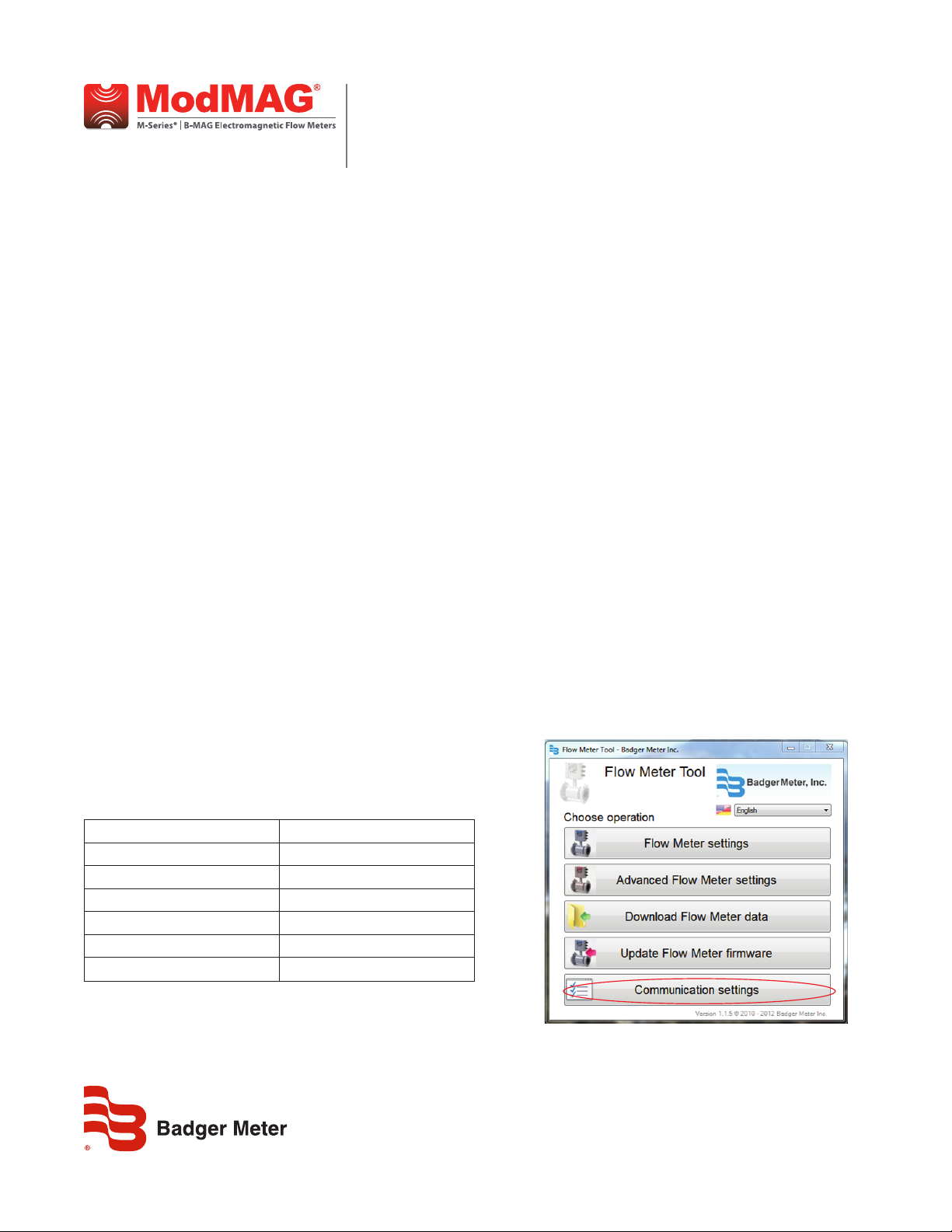
5. Open the Flow Meter Tool installed on the laptop or PC. Go to
Start > All Programs > Badger Meter to open the Flow Meter Tool
application.
6. To congure the Flow Meter Tool software communication
settings:
a. Select Communication Settings.
Interval Totalizer / Error Events
1 minute 7224 minutes (5 days)
15 minutes 75-1/4 days
1 hour 301 days
6 hours 1806 days
12 hours 3612 days
24 hours 7224 days
Conguration Events
Each Configuration event identifies the parameter that was
modified and to what value the parameter was changed. A total of
20 configuration events can be recorded.
MAG-UM-00944-EN-04 (February 2016)
User Manual
Page 2
M-Series® M5000, Data Logging
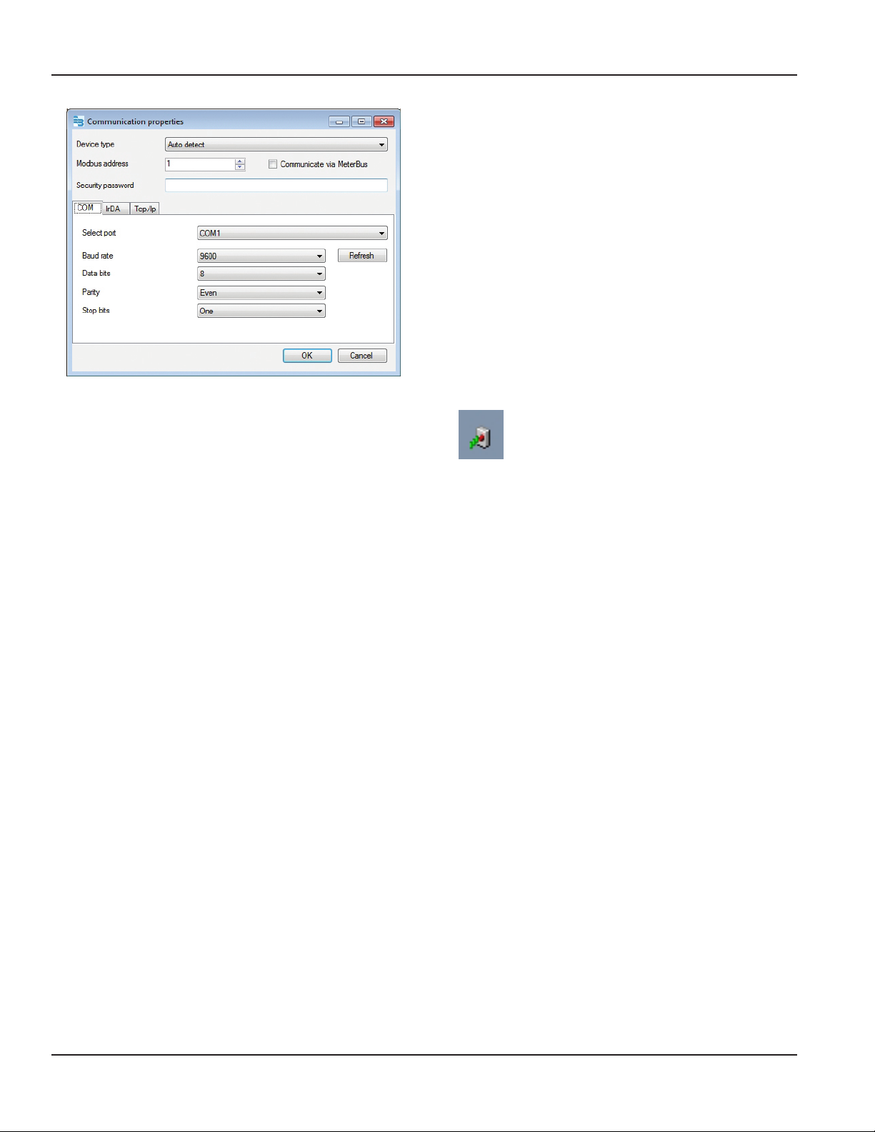
b. Change the following parameters as necessary to
align with the meter settings:
• MODBUS ADDRESS (Node Address)
• BAUD RATE (9600)
• DATA BITS (default is 8)
• PARITY
• STOP BITS (default is 1)
c. Select OK to confirm the configuration of the
communication port. Make sure you select the
correct COM port.
OTE:N The M5000 communicates via the COM port and IrDA.
TCP/IP is not supported.
4. To extract the event les:
a. Select Download Flowmeter Data.
b. Select the Totalizer and Error Log tab.
c. Select Download.
d. Optional: Select Save as Excel file… for each event
file to save the history of events.
e. Select the Startup Log tab.
f. Select Download.
g. Optional: Select Save as Excel file… for each event
file to save the history of events.
h. Select the Configuration Event Log tab.
i. Select Download.
j. Optional: Select Save as Excel file… for each event
file to save the history of events.
k. Select Cancel to exit this application window.
IrDA Link File Extraction
1. Identify / Congure the meter’s communication settings:
a. Navigate to Communications > Interface.
b. Set the interface to IrDA.
OTE:N The interface must be set to IrDA. All other settings can
be set as desired by the operator and must match those
settings of the software tool.
3. On the M5000 enclosure, install the IrDA bracket, then install the
IrDA cable.
4. Connect the IrDA cable from the M5000 to the laptop.
5. If necessary, install the IrDA link drivers from the CD. The IrDA
link uses a USB/IrDA converter and drivers. You may have to
restart your computer after installing the drivers.
When the IrDA communication is activated, an icon appears on the
lower part of your screen.
The Wireless Link icon in the taskbar is a function of Windows®, not
the Flow Meter Tool.
6. In the Flow Meter Tool, select IrDA from the Communication
Settings menu. If there are multiple IrDA interfaces, make sure
you select the right one.
7. To extract the event les:
a. Select Download Flowmeter Data.
b. Select the Totalizer and Error Log tab.
c. Select Download.
d. Optional: Select Save as Excel file… for each event
file to save the history of events.
e. Select the Startup Log tab.
f. Select Download.
g. Optional: Select Save as Excel file… for each event
file to save the history of events.
h. Select the Configuration Event Log tab.
i. Select Download.
j. Optional: Select Save as Excel file… for each event
file to save the history of events.
k. Select Cancel to exit this application window.
MAG-UM-00944-EN-04Page 2 February 2016
Page 3

User Manual
INSTALLING THE FLOW METER TOOL
1. Insert the CD containing the Flow Meter les.
The autorun tool displays the Welcome screen.
2. Click Next to conrm that you want to install the tool.
3. On the Select Installation Folder screen, select the folder where
you would like the tool installed. Click Next.
5. When the installation is complete, click Close.
ALTERNATE FLOW METER TOOL
INSTALLATION METHOD
If the CD does not automatically open:
1. Navigate to the CD disk location.
2. Click on the Badger Meter Flow Meter Tool folder to open it.
4. Wait while the tool installs.
3. Double-click the index.htm le to open it.
4. On the Flow Meter Tool window, select Click here to run
installer of Flow Meter tool.
5. Perform Steps 3 through 5 under “Installing the Flow Meter Tool”
on page 3 in this document to complete the installation.
MAG-UM-00944-EN-04 Page 3 February 2016
Page 4

M-Series® M5000, Data Logging
Control. Manage. Optimize.
M-SERIES and ORION are registered trademarks of Badger Meter, Inc. Other trademarks appearing in this document are the property of their respective entities. Due to continuous
research, product improvements and enhancements, Badger Meter reserves the right to change product or system specications without notice, except to the extent an
outstanding contractual obligation exists. © 2016 Badger Meter, Inc. All rights reserved.
www.badgermeter.com
The Americas | Badger Meter | 4545 West Brown Deer Rd | PO Box 245036 | Milwaukee, WI 53224-9536 | 800-876-3837 | 414-355-0400
México | Badger Meter de las Americas, S.A. de C.V. | Pedro Luis Ogazón N°32 | Esq. Angelina N°24 | Colonia Guadalupe Inn | CP 01050 | México, DF | México | +52-55-5662-0882
Europe, Middle East and Africa | Badger Meter Europa GmbH | Nurtinger Str 76 | 72639 Neuen | Germany | +49-7025-9208-0
Europe, Middle East Branch Oce | Badger Meter Europe | PO Box 341442 | Dubai Silicon Oasis, Head Quarter Building, Wing C, Oce #C209 | Dubai / UAE | +971-4-371 2503
Czech Republic | Badger Meter Czech Republic s.r.o. | Maříkova 2082/26 | 621 00 Brno, Czech Republic | +420-5-41420411
Slovakia | Badger Meter Slovakia s.r.o. | Racianska 109/B | 831 02 Bratislava, Slovakia | +421-2-44 63 83 01
Asia Pacic | Badger Meter | 80 Marine Parade Rd | 21-06 Parkway Parade | Singapore 449269 | +65-63464836
China | Badger Meter |
7-1202 | 99 Hangzhong Road | Minhang District | Shanghai | China 201101 | +86-21-5763 5412 Legacy Document Number: IOM-839-01-EN 53400-839
 Loading...