

Page 1
High Resolution LCD Encoder Programmer
HR-E® LCD, HR-E® LCD 4-20
ENC-PM-02040-EN-03 (May 2018)
Programmer Manual
Page 2

High Resolution LCD Encoder Programmer
Page ii May 2018ENC-PM-02040-EN-03
Page 3

Programmer ManualProgrammer Manual
CONTENTS
Introduction . . . . . . . . . . . . . . . . . . . . . . . . . . . . . . . . . . . . . . . . . . . . . . . . . . . . . . . . . . . . . . . . . . . . . . . . 5
System Requirements . . . . . . . . . . . . . . . . . . . . . . . . . . . . . . . . . . . . . . . . . . . . . . . . . . . . . . . . . . . . . . . . . . 5
Parts List . . . . . . . . . . . . . . . . . . . . . . . . . . . . . . . . . . . . . . . . . . . . . . . . . . . . . . . . . . . . . . . . . . . . . . . . . . 5
IR Head Bracket . . . . . . . . . . . . . . . . . . . . . . . . . . . . . . . . . . . . . . . . . . . . . . . . . . . . . . . . . . . . . . . . . . . . . . 6
Attaching the bracket to an encoder . . . . . . . . . . . . . . . . . . . . . . . . . . . . . . . . . . . . . . . . . . . . . . . . . . . . . . 6
Removing the bracket from an encoder . . . . . . . . . . . . . . . . . . . . . . . . . . . . . . . . . . . . . . . . . . . . . . . . . . . . 6
Using the Programmer Software . . . . . . . . . . . . . . . . . . . . . . . . . . . . . . . . . . . . . . . . . . . . . . . . . . . . . . . . . . . 7
Performing a Read . . . . . . . . . . . . . . . . . . . . . . . . . . . . . . . . . . . . . . . . . . . . . . . . . . . . . . . . . . . . . . . . . . 8
Read Errors . . . . . . . . . . . . . . . . . . . . . . . . . . . . . . . . . . . . . . . . . . . . . . . . . . . . . . . . . . . . . . . . . . . .8
Encoder Types . . . . . . . . . . . . . . . . . . . . . . . . . . . . . . . . . . . . . . . . . . . . . . . . . . . . . . . . . . . . . . . . . . . . 9
Change Current Settings . . . . . . . . . . . . . . . . . . . . . . . . . . . . . . . . . . . . . . . . . . . . . . . . . . . . . . . . . . . . . 10
Apply Current Settings . . . . . . . . . . . . . . . . . . . . . . . . . . . . . . . . . . . . . . . . . . . . . . . . . . . . . . . . . . . . . . 10
Updating Multiple Encoders . . . . . . . . . . . . . . . . . . . . . . . . . . . . . . . . . . . . . . . . . . . . . . . . . . . . . . . . 10
Programmer Parameters . . . . . . . . . . . . . . . . . . . . . . . . . . . . . . . . . . . . . . . . . . . . . . . . . . . . . . . . . . . . . . . 11
Serial # Field . . . . . . . . . . . . . . . . . . . . . . . . . . . . . . . . . . . . . . . . . . . . . . . . . . . . . . . . . . . . . . . . . . . . . 11
Version Field. . . . . . . . . . . . . . . . . . . . . . . . . . . . . . . . . . . . . . . . . . . . . . . . . . . . . . . . . . . . . . . . . . . . . 11
Meter Type Field . . . . . . . . . . . . . . . . . . . . . . . . . . . . . . . . . . . . . . . . . . . . . . . . . . . . . . . . . . . . . . . . . . 11
Meter Model/Size Field . . . . . . . . . . . . . . . . . . . . . . . . . . . . . . . . . . . . . . . . . . . . . . . . . . . . . . . . . . . . . . 12
Unit of Measure Field . . . . . . . . . . . . . . . . . . . . . . . . . . . . . . . . . . . . . . . . . . . . . . . . . . . . . . . . . . . . . . . 12
Billing Units Field. . . . . . . . . . . . . . . . . . . . . . . . . . . . . . . . . . . . . . . . . . . . . . . . . . . . . . . . . . . . . . . . . . 13
Digits from Encoder Field . . . . . . . . . . . . . . . . . . . . . . . . . . . . . . . . . . . . . . . . . . . . . . . . . . . . . . . . . . . . 13
Visual Reading and Encoder Output Fields . . . . . . . . . . . . . . . . . . . . . . . . . . . . . . . . . . . . . . . . . . . . . . . . . 14
Rate of Flow Units Field. . . . . . . . . . . . . . . . . . . . . . . . . . . . . . . . . . . . . . . . . . . . . . . . . . . . . . . . . . . . . . 14
Rate of Flow Time Field . . . . . . . . . . . . . . . . . . . . . . . . . . . . . . . . . . . . . . . . . . . . . . . . . . . . . . . . . . . . . . 15
Deactivate 6-Digit Display . . . . . . . . . . . . . . . . . . . . . . . . . . . . . . . . . . . . . . . . . . . . . . . . . . . . . . . . . . . . 15
View Indicators . . . . . . . . . . . . . . . . . . . . . . . . . . . . . . . . . . . . . . . . . . . . . . . . . . . . . . . . . . . . . . . . . . . 16
Clear Reading . . . . . . . . . . . . . . . . . . . . . . . . . . . . . . . . . . . . . . . . . . . . . . . . . . . . . . . . . . . . . . . . . . . . 16
4-20 mA Parameters. . . . . . . . . . . . . . . . . . . . . . . . . . . . . . . . . . . . . . . . . . . . . . . . . . . . . . . . . . . . . . . . 17
Exiting the Software Application . . . . . . . . . . . . . . . . . . . . . . . . . . . . . . . . . . . . . . . . . . . . . . . . . . . . . . . . . . 18
Appendix
Installing the Programmer Software . . . . . . . . . . . . . . . . . . . . . . . . . . . . . . . . . . . . . . . . . . . . . . . . . . . . . . . . 20
COM Port . . . . . . . . . . . . . . . . . . . . . . . . . . . . . . . . . . . . . . . . . . . . . . . . . . . . . . . . . . . . . . . . . . . . . . . . . 22
Troubleshooting . . . . . . . . . . . . . . . . . . . . . . . . . . . . . . . . . . . . . . . . . . . . . . . . . . . . . . . . . . . . . . . . . . . . 22
Page iii May 2018 ENC-PM-02040-EN-03
Page 4

High Resolution LCD Encoder Programmer
Page iv May 2018ENC-PM-02040-EN-03
Page 5
Introduction
INTRODUCTION
This manual has instructions for programming HR-E LCD and HR-E LCD 4-20 high resolution (HR) encoders. Instructions for
installing the Programmer software can be found in the "Appendix" on page 19.
Audience and Purpose
This manual is intended to be used by utilities for programming Badger Meter high resolution encoders.
SYSTEM REQUIREMENTS
A computer with a Windows® 7 (or newer) operating system is required for programming the HR LCD encoders.
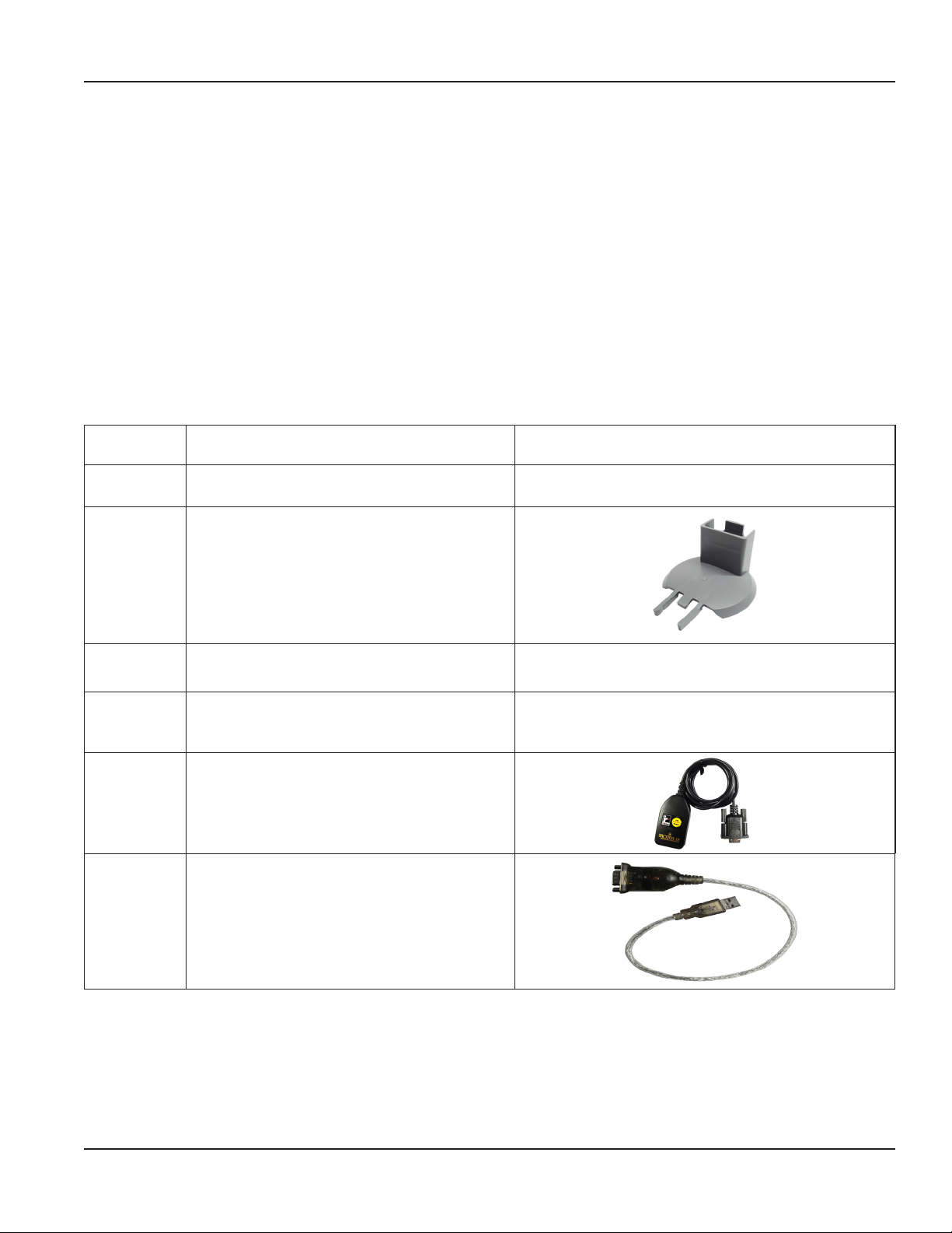
PARTS LIST
The following parts are necessary for programming HR LCD encoders.
67660-001 Programming kit (CD)
68468-001 Programming kit (USB)
Kit includes IR head bracket, programmer software (USB)
Kit includes IR head bracket and
programmer software (CD)
and programming cable (USB)
67451-001
67572-009
67572-012
64436-042
64436-029
OTE:N Software version 2.0.x is required for programming the HR-E LCD 4-20 encoder.
(Included in the 67660-001, 68468-001 kits)
HR-E LCD encoder programmer software (CD)
(Included in the 67660-001 kit)
HR-E LCD encoder programmer software (USB)
(Included in the 68468-001 kit)
IR programming and data profile cable
(Required, but not included in the
IR head bracket
Available on USB flash drive
67660-001 kit)
Serial-to-USB adapter
(Optional)
Available on CD
Page 5 May 2018 ENC-PM-02040-EN-03
Page 6
IR Head Bracket
IR HEAD BRACKET
To facilitate reading and programming multiple encoders, the IR head bracket is recommended. The bracket is easy to attach
and remove.
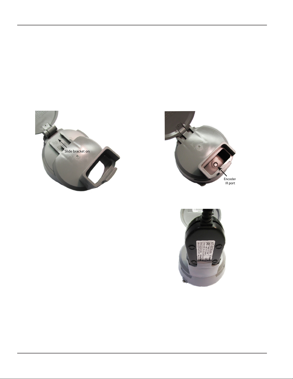
Attaching the bracket to an encoder
1. Open the lid of the encoder.
2. With the bracket guide pointing to the encoder lid hinge, slide the bracket onto the encoder (Figure 2) so the guide
ts on both sides of the hinge.
Push gently to make sure the bracket guide is completely seated against the encoder lid hinge, and you can see the
IR port through bracket opening as shown in Figure 2.
Figure 1: Slide bracket onto encoder
3. Place the optical head of the IR cable in the bracket,
with the nubs on the back seated in the slots of the
bracket. See Figure 3. This placement facilitates correct
alignment between the IR head and the encoder
IR port.
The encoder is ready for programming.
Figure 2: Bracket attached to encoder - top view
Figure 3: Head of IR cable inserted
Removing the bracket from an encoder
When you are finished programming an encoder, remove the bracket.
Hold the encoder with one hand and pull the bracket gently with the other hand, straight off the encoder. The bracket should
come off will little resistance.
Page 6 May 2018ENC-PM-02040-EN-03
Page 7

Using the Programmer Software
USING THE PROGRAMMER SOFTWARE
Use the Programmer software to view and change the parameters that are currently programmed into the encoder, and
program new parameters, if needed. You can also clear the encoder reading.
OTE:N If you need help installing the software, see the instructions "Installing the Programmer Software" on page 20.
1. Connect the IR programming and data prole cable (IR cable) to the serial port of the computer with the installed
programming software.
If the computer does not have a serial port, use a Serial-to-USB adapter. See the "Parts List" on page 5.
OTE:N Connect the IR cable before you start the software to make sure the software recognizes the
IR cable connection.
2. Double-click the LCD Programmer shortcut to
start the software application.
The License Agreement displays the first time you
access the software.
Figure 4: Software shortcut
3. Read the License Agreement and click
Accept License.
OTE:N The License Agreement must be accepted
by an authorized representative of the
customer/licensee. If you select Decline
License, the application will not start.
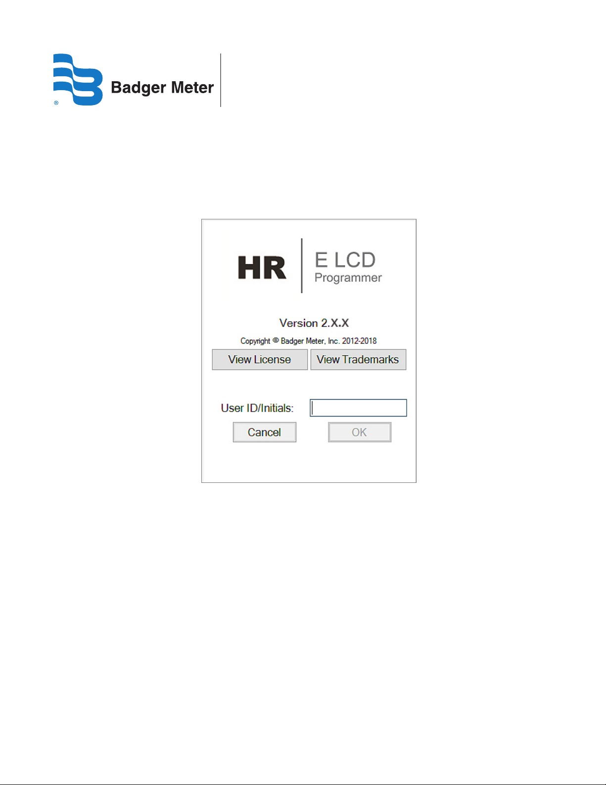
The Splash (sign-in) screen displays (Figure 6). The
screen includes the software version, access to the
license and trademarks information, and the User
ID/Initials field.
Figure 5: Software license agreement
4. Enter your initials in the UserID/Initials eld.
A user ID of 3…7 characters is required to activate
the OK button.
Then click OK.
OTE:N Your sign-in initials are used in the product
log file to record any changes you make to
the LCD encoder.
The software Programmer screen opens.
Figure 6: Splash screen
Page 7 May 2018 ENC-PM-02040-EN-03
Page 8
Using the Programmer Software
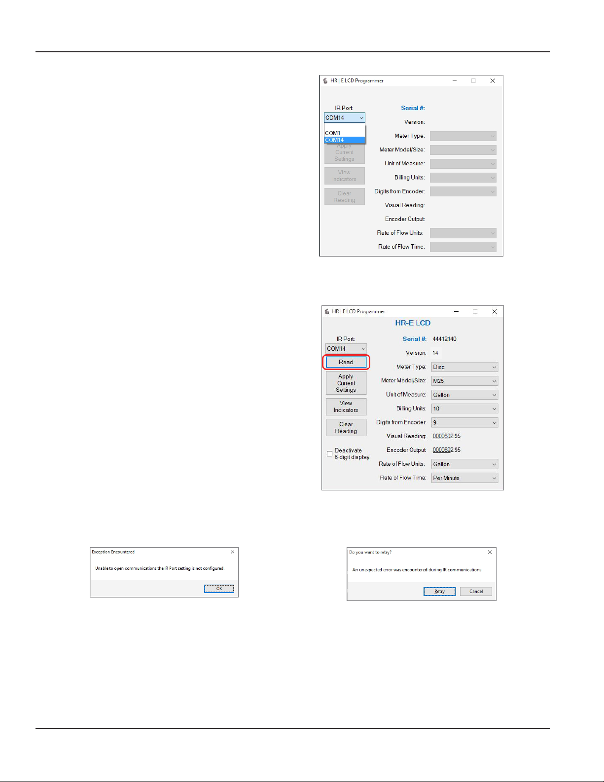
5. When the Programmer screen opens, select
the correct COM port for the IR cable using the
IR Port drop-down menu.
OTE:N If the correct COM port is not selected,
the software will be unable to read the
encoder. For help with the COM port,
see "COM Port" on page 22.
Performing a Read
Make sure the IR head is aligned with the IR port of the
encoder. Then click the Read button.
If the correct COM port is selected and a good response
is received, the software determines the encoder type
and populates the Programmer screen data fields as
shown in Figure 8. For more information, see"Encoder
Types" on page 9.
If the encoder is programmed the way you want,
disconnect it from the IR bracket. If not, see "Change
Current Settings" on page 10.
Figure 7: Select the COM port
Figure 8: Encoder Read
Read Errors
If no COM port is selected, the error message in Figure 9 displays. Click OK, select the COM port, and click Read again.
Figure 9: No COM port selected
Figure 10: Wrong COM port selected
If the wrong COM port is selected, the error message in Figure 10 displays. Click Cancel, select the correct COM port, and click
Read again.
Page 8 May 2018ENC-PM-02040-EN-03
Page 9

Using the Programmer Software
Encoder Types
When you read the device with the IR cable, the software automatically detects the encoder type. The device type and serial
number display at the top of the screen. Software parameters that display on the screen vary depending on the device type.
Examples of completed Programmer screens for all three device types are displayed here.
Figure 11: HR-E LCD screen
Figure 12: HR-E LCD 4-20 screen
OTE:N The HR-E LCD encoder is used for the examples throughout this manual, unless otherwise indicated.
Page 9 May 2018 ENC-PM-02040-EN-03
Page 10

Using the Programmer Software
Change Current Settings
To change the encoder settings and set a new default value for any of the data fields, follow this procedure.
1. Click the drop-down menu to the right of the
eld to display a list of values.
2. Click the value you want to set as the default
for that eld.
OTE:N The eld label changes to bold text, indicating
a new, unprogrammed value is selected. See
Figure 13.
OTE:N You must set the default value for the
Meter Type field before you set the
Meter Model / Size. The Unit of Measure value
does not have to be the same as the
Rate of Flow Units. (Even in a cubic foot meter,
the flow rate can be gallons per minute.)
Figure 13: Unprogrammed values
Apply Current Settings
If you make a change on the Programmer screen, you must apply the change to the encoder.
With the IR head aligned, click Apply Current Settings to program the new values to the encoder.
The new values display on the Programmer screen and the field labels are no longer bold. The encoder also goes into storage
mode. In storage mode, the encoder displays the meter type, digit resolution from the encoder and unit of measure. This is an
example of an encoder display of a Model 25 Disc Meter with a 9-digit output, measuring in gallons:
GAL
Figure 14: Meter type, digit resolution from the encoder and unit of measure
Updating Multiple Encoders
If you have multiple encoders to program with the same settings, attach the IR head bracket with the IR cable to each
encoder, one at a time, and click Apply Current Settings to program each encoder with the same settings.
Page 10 May 2018ENC-PM-02040-EN-03
Page 11

Programmer Parameters
PROGRAMMER PARAMETERS
The Programmer fields are described in this section. The description applies to all encoder types unless otherwise indicated.
Serial # Field
The Serial # (number) field (Figure 15) is a read-only field that displays the encoder factory-assigned serial number. You cannot
change this number.
Version Field
The Version field (Figure 15) is a read-only field that displays the encoder version. You cannot change the value in this field.
Figure 15: Serial and Version number
Meter Type Field
The Meter Type field (Figure 16) displays the type of meter to which the encoder can connect.
Click the drop-down menu to the right of the data field to select the Meter Type. Available options are Disc, CSM (Compound),
and TSM (Turbo).
Figure 16: Meter Types
Page 11 May 2018 ENC-PM-02040-EN-03
Page 12

Programmer Parameters
Meter Model/Size Field
The Meter Model/Size field (Figure 17) auto-populates based on the Meter Type selected.
Click the drop-down menu to the right of the data field to select a Meter Model. Meter Sizes corresponding to the Meter
Models in the drop-down menu are shown in the table below Figure 17.
Figure 17: Meter Model and Size
For Recordall® Combination Fire Service meters and assemblies, refer to the Disc and TSM columns of the table.
Disc (inches) Model CSM (inches) Model TSM (inches) Model
5/8, 5/8 x 3/4 LP 2 High Side 1-1/2 T160
5/8, 5/8 x 3/4 M25 2 Low Side 2 T200
3/4 M35 3 High Side 3 T450
1 M40 3 Low Side 4 T1000
1 M55 4 High Side 6 T2000
1 M70 4 Low Side 8 T3500
1-1/2 M120 6 High Side 10 T5500
2 M170 6 Low Side 12 T6200
16 T6600
20 T10000
Unit of Measure Field
The Unit of Measure field (Figure 18) displays the unit selected to measure the flow.
Click the drop-down menu to the right of the data field to select a Unit of Measure. The options are gallon, cubic meter, liters,
cubic feet and imperial gallon.
Figure 18: Unit of Measure
Page 12 May 2018ENC-PM-02040-EN-03
Page 13

Programmer Parameters
Billing Units Field
The Billing Units field (Figure 19) displays the default units for which the customer is billed, and is indicated by dashed lines
above and below the totalizer reading. The default is based on the Unit of Measure selected:
Unit of Measure Default Billing Unit
Gallons, liters, imperial gallons 1000
Cubic feet 100
Cubic meters 1
Click the drop-down menu to the right of the data field to select a Billing Units value. If you do not want the dashed lines to
display, select “0“ (zero) as the Billing Units value.
Figure 19: Billing Units
Digits from Encoder Field
The Digits from Encoder field (Figure 20) displays the number of digits the encoder is programmed to send to the endpoint.
These options include 4, 5, 6, 7*, 8* and 9 digits. Readings reported from an encoder programmed to 4, 5, 6, 7 and 8 digits are
the left-most significant digits. Changing this value affects the Encoder Output field.
Click the drop-down menu to the right of the data field to select a different encoder output resolution.
* The 7- and 8-digit options apply to encoders with version 14 or later.
Figure 20: Encoder digits
MPORTANTI
Be very careful with the Digits from Encoder feature! Changes will affect the reading resolution sent to the endpoint and in your
reading data management system.
Page 13 May 2018 ENC-PM-02040-EN-03
Page 14

Programmer Parameters
Visual Reading and Encoder Output Fields
The Visual Reading* field is a read-only field that displays the current meter reading as a real number. The number of decimal
places is determined by the units and meter size. You cannot change this number.
The Encoder Output* field is a read-only field that displays the reading resolution sent from the encoder. Changing the
Digits from Encoder field affects the Encoder Output field. See Figure 21 for an example of both fields.
*For TSM (Turbo) 12…20 inch meters, the value shown in the Visual Reading field and Encoder Output field may not display correctly. The programming value,
however, is calculated correctly and will display correctly on the encoder.
Figure 21: Visual Reading and Encoder Output
Rate of Flow Units Field
The Rate of Flow Units field displays the unit by which the rate of flow is measured. The factory-programmed default is Gallon.
Click the drop-down menu to the right of the data field to select a Rate of Flow Units. The options are gallon, cubic meter,
liters, cubic feet and imperial gallon as shown in Figure 22.
Figure 22: Rate of Flow Units
Page 14 May 2018ENC-PM-02040-EN-03
Page 15

Programmer Parameters
Rate of Flow Time Field
The Rate of Flow Time field displays the time unit set for the rate of flow. The factory-programmed default is Per Minute.
Click the drop-down menu to the right of the data field to select a Rate of Flow Time. The options are seconds, minutes or
hours as shown in Figure 23.
Figure 23: Rate of Flow Time
Deactivate 6-Digit Display
The Deactivate 6-digit display field can be used to remove the 6-digit consumption display from the encoder automatic
display. See the High Resolution LCD Encoders User Manual, available at www.badgermeter.com, for additional information.
Click the box to the left of the field to select it. When the box is checked, the display automatically toggles between the 9-digit
consumption display, the rate of flow and the meter model.
Figure 24: Deactivate 6-digit display
Page 15 May 2018 ENC-PM-02040-EN-03
Page 16

Programmer Parameters
View Indicators
The View Indicators button (Figure 25) displays the current status indicators for the selected meter.
Status indicator options are Encoder Removal, 30 Day No Usage, Suspected Leak, Programmed, End of Battery Life,
Reverse Flow, Magnetic Tamper and Temperature Limit Exceeded. See the High Resolution LCD Encoders User Manual, available
at www.badgermeter.com, for descriptions of these indicators.
1. With the IR head aligned, click View Indicators. The Status Indicators pop-up window displays (Figure 26).
2. To clear the indicators, click Clear Indicators in the pop-up window.
OTE:N The Clear Indicators button does NOT clear the Programmed indicator.
3. Click Close to exit the window.
Figure 26: Status Indicators
Figure 25: View Indicators
Clear Reading
The Clear Reading button (Figure 27) deletes ALL readings for the selected meter.
MPORTANTI
Be very careful with the Clear Reading feature! If you select this option, a pop-up message displays (Figure 28), asking for a
password to confirm the deletion. Contact Badger Meter Technical Support for the password.
Figure 28: Password required
Figure 27: Clear all readings
Page 16 May 2018ENC-PM-02040-EN-03
Page 17

Programmer Parameters
4-20 mA Parameters
OTE:N These parameters apply to the HR-E LCD 4-20 encoder.
The 4-20 mA Parameters field (Figure 29) displays the parameters of the encoder analog control signal. The 4-20 mA output
signal is directly proportional to the meter rate of flow. For default measurement resolution values, see the Measurement
Resolution charts in the High Resolution LCD Encoder User Manual, available at www.badgermeter.com.
Figure 29: 4-20 mA Parameters
• The 4 mA field is always set to zero (0). The register produces a 4 mA signal at zero flow.
• The 20 mA Setting field displays the flow rate setting. Set this parameter to the flow rate at which the output should
generate to maximum signal. In most cases, this is the maximum flow rate of the meter.
• The Damping Factor is the value used to stabilize the analog output signal.
Page 17 May 2018 ENC-PM-02040-EN-03
Page 18

Exiting the Software Application
EXITING THE SOFTWARE APPLICATION
To exit and close the software application, click the X in the top right corner of the software screen as shown in Figure 30.
Figure 30: Click the X to exit software
Page 18 May 2018ENC-PM-02040-EN-03
Page 19

APPENDIX
Appendix
Page 19 May 2018 ENC-PM-02040-EN-03
Page 20

Installing the Programmer Software
INSTALLING THE PROGRAMMER SOFTWARE
Follow these steps for installing the software.
1. Double-click the setup.exe le to begin installation. The Welcome screen displays.
Figure 31: Software Installer Wizard Welcome screen
2. Click Next. The Select Installation Folder screen displays.
Figure 32: Software files location
3. Click Next to choose Program Files, the default location folder, or click Browse to choose another location.
The confirmation screen displays.
Page 20 May 2018ENC-PM-02040-EN-03
Page 21

Installing the Programmer Software
Figure 33: Ready to install
4. Click Next to start installation. A progress bar displays briey. Then the Installation Complete screen displays.
Figure 34: Progress bar shows installation in progress
5. At the Installation Complete screen, click Close to exit the installer. The Programmer shortcut displays on the
computer desktop.
Figure 35: Installation complete
Page 21 May 2018 ENC-PM-02040-EN-03
Page 22

COM Port
COM PORT
The Programmer software communicates with the encoder through the encoder IR port using the IR programming and data
prole cable (IR cable). You must identify the correct communication (COM) port for the IR cable to make sure the software
can communicate with the encoder. Follow these steps to identify the correct COM port for the IR cable connected to
the computer.
1. Connect the IR cable to the serial port of the computer. If the computer does not have a serial port, use a
serial-to-USB adapter.
Follow these instructions to identify the COM port:
• Select the Microsoft Start button.
• Right-click on Computer*.
• Select Manage.
• Select Device Manager from the menu
on the left.
• In the Device Manager window, click
the arrow next to Ports (COM & LPT) to
expand the selection.
• Find the COM port for the IR cable. The
example (Figure 36) shows COM 7 for
the IR cable connected with a USB to
serial adapter, “Prolific USB-to-Serial
Comm Port.“
2. Write down the COM port number for use
with the Programmer software.
* If you have Windows 8 or 10, type “Device Manager“ in the Search field to open the Device Manager screen.
Figure 36: COM port in Device Manager window
TROUBLESHOOTING
Issue Probable Cause Solution
Programmer screen is blank after
a Read.
Error message displayed after clicking
an option on the programmer screen.
Encoder alarm
Also see "Read Errors" on page 8.
COM port not specied.
Bad connection. Check for damaged or broken wires.
IR head not aligned with the device.
While in regular operational mode,
the device is tilted or removed from
the meter.
Select the correct COM port from the IR
Port drop-down menu.
Align the head of the IR cable with the
IR port on the device and try again.
Align the head of the IR cable with
the IR port on the device. Keep the
device still.
Page 22 May 2018ENC-PM-02040-EN-03
Page 23

INTENTIONAL BLANK PAGE
Programmer Manual
Page 23 May 2018 ENC-PM-02040-EN-03
Page 24

High Resolution LCD Encoder Programmer, HR-E® LCD, HR-E® LCD 4-20
Making Water Visible®
HR-E, Making Water Visible and Recordall are registered trademarks of Badger Meter, Inc. Other trademarks appearing in this document are the property of their respective entities.
Due to continuous research, product improvements and enhancements, Badger Meter reserves the right to change product or system specications without notice, except to the
extent an outstanding contractual obligation exists. © 2018 Badger Meter, Inc. All rights reserved.
www.badgermeter.com
The Americas | Badger Meter | 4545 West Brown Deer Rd | PO Box 245036 | Milwaukee, WI 53224-9536 | 800-876-3837 | 414-355-0400
México | Badger Meter de las Americas, S.A. de C.V. | Pedro Luis Ogazón N°32 | Esq. Angelina N°24 | Colonia Guadalupe Inn | CP 01050 | México, DF | México | +52-55-5662-0882
Europe, Eastern Europe Branch Oce (for Poland, Latvia, Lithuania, Estonia, Ukraine, Belarus) | Badger Meter Europe | ul. Korfantego 6 | 44-193 Knurów | Poland | +48-32-236-8787
Europe, Middle East and Africa | Badger Meter Europa GmbH | Nurtinger Str 76 | 72639 Neuen | Germany | +49-7025-9208-0
Europe, Middle East Branch Oce | Badger Meter Europe | PO Box 341442 | Dubai Silicon Oasis, Head Quarter Building, Wing C, Oce #C209 | Dubai / UAE | +971-4-371 2503
Slovakia | Badger Meter Slovakia s.r.o. | Racianska 109/B | 831 02 Bratislava, Slovakia | +421-2-44 63 83 01
Asia Pacic | Badger Meter | 80 Marine Parade Rd | 21-06 Parkway Parade | Singapore 449269 | +65-63464836
China | Badger Meter | 7-1202 | 99 Hangzhong Road | Minhang District | Shanghai | China 201101 | +86-21-5763 5412
Switzerland | Badger Meter Swiss AG | Mittelholzerstrasse 8 | 3006 Bern | Switzerland | +41-31-932 01 11
Legacy Document Number: LCD-IOM-01-EN
 Loading...