

Page 1
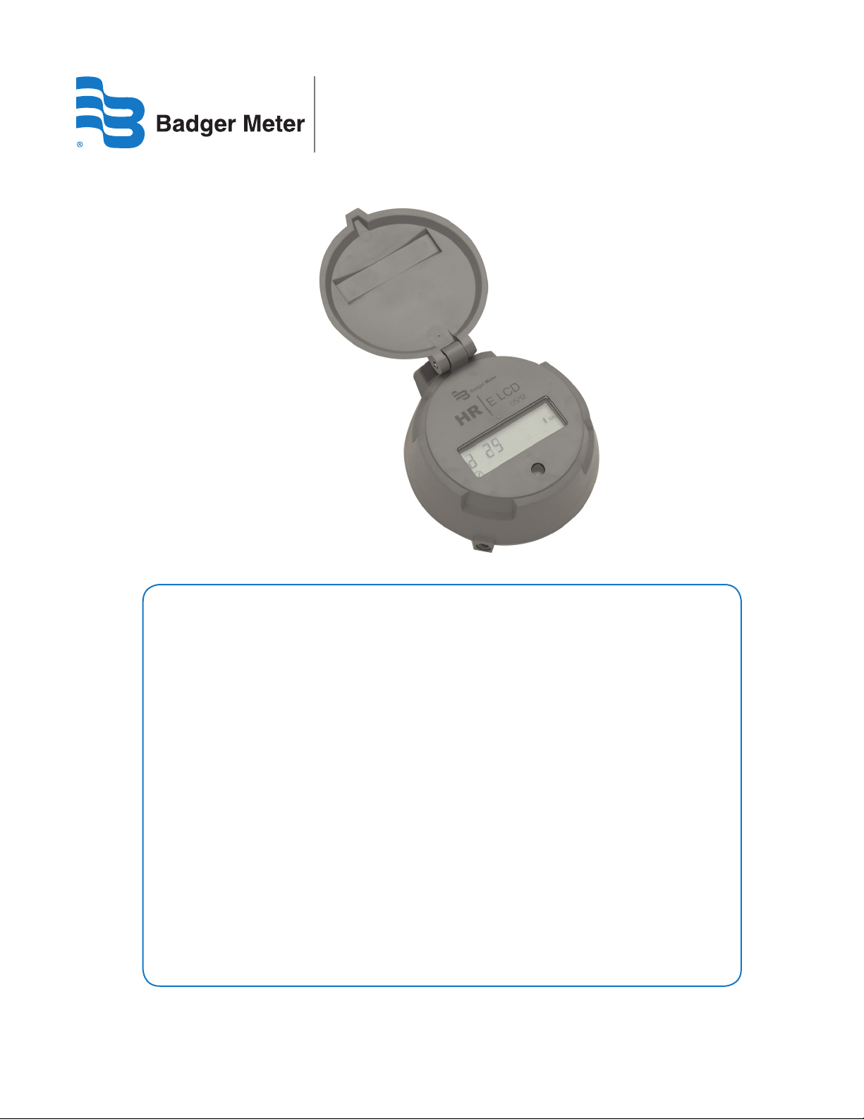
HR | E LCD Encoder
IMPORTARI
For proper handling of the higher reading resolution and the extended status indicator
capabilities of the HR-E LCD encoder, the following software versions are required for your
reading system:
Reading Data Management Software
• ReadCenter Data: Version 1.11.12.27 or higher (does not include extended status
indicator capabilities
• ReadCenter Analytics and ReadCenter Analytics Mobile: Version 2.12.7.6 or later
Mobile Reading Systems
• ORS: Version 2.2.1 or later
Handheld Reading Systems
• Badger Field Application Suite: Version 2.2.3 or later
• ORION Field Application route reading software: Version 2.2.3 or later
• ORION Endpoint Utility programming & quick read software: Version 2.2.2 or later
Please contact Badger Meter Technical Support at 1-800-456-5023 or the appropriate endpoint
provider if you need assistance.
LCD-IOM-01-EN (December 2012)
62014-159 Rev. 1
Installation and
Programming Manual
Page 2

HR | E LCD Encoder
Page ii December 2012
Page 3

Installation and Programming Manual
CONTENTS
INTRODUCTION . . . . . . . . . . . . . . . . . . . . . . . . . . . . . . . . . . . . . . . . . . . . . . . . . . . . . . . . 5
Product Unpacking and Inspection. . . . . . . . . . . . . . . . . . . . . . . . . . . . . . . . . . . . . . . . . . . 5
License Requirements . . . . . . . . . . . . . . . . . . . . . . . . . . . . . . . . . . . . . . . . . . . . . . . . . . . 5
Audience and Purpose. . . . . . . . . . . . . . . . . . . . . . . . . . . . . . . . . . . . . . . . . . . . . . . . . . .5
PRODUCT OVERVIEW . . . . . . . . . . . . . . . . . . . . . . . . . . . . . . . . . . . . . . . . . . . . . . . . . . . . .5
Description . . . . . . . . . . . . . . . . . . . . . . . . . . . . . . . . . . . . . . . . . . . . . . . . . . . . . . . . . . 5
Compatibility. . . . . . . . . . . . . . . . . . . . . . . . . . . . . . . . . . . . . . . . . . . . . . . . . . . . . . . . .5
LCD Display. . . . . . . . . . . . . . . . . . . . . . . . . . . . . . . . . . . . . . . . . . . . . . . . . . . . . . . . . .5
Visual Display . . . . . . . . . . . . . . . . . . . . . . . . . . . . . . . . . . . . . . . . . . . . . . . . . . . . . . . . 6
Units of Measure . . . . . . . . . . . . . . . . . . . . . . . . . . . . . . . . . . . . . . . . . . . . . . . . . . . .6
9-Digit Totalization . . . . . . . . . . . . . . . . . . . . . . . . . . . . . . . . . . . . . . . . . . . . . . . . . . .6
6-Digit Totalization . . . . . . . . . . . . . . . . . . . . . . . . . . . . . . . . . . . . . . . . . . . . . . . . . . .6
Rate of Flow . . . . . . . . . . . . . . . . . . . . . . . . . . . . . . . . . . . . . . . . . . . . . . . . . . . . . . .6
Meter Model Information . . . . . . . . . . . . . . . . . . . . . . . . . . . . . . . . . . . . . . . . . . . . . . .7
Visual Measurement Resolution. . . . . . . . . . . . . . . . . . . . . . . . . . . . . . . . . . . . . . . . . . . . .8
Status Indicators. . . . . . . . . . . . . . . . . . . . . . . . . . . . . . . . . . . . . . . . . . . . . . . . . . . . . . .9
INSTALLING THE HRE LCD ENCODER . . . . . . . . . . . . . . . . . . . . . . . . . . . . . . . . . . . . . . . . . 10
Bayonet Mount . . . . . . . . . . . . . . . . . . . . . . . . . . . . . . . . . . . . . . . . . . . . . . . . . . . . . . 10
Wire Connections . . . . . . . . . . . . . . . . . . . . . . . . . . . . . . . . . . . . . . . . . . . . . . . . . . . . . 10
308 In-Line Connector . . . . . . . . . . . . . . . . . . . . . . . . . . . . . . . . . . . . . . . . . . . . . . . . . . 10
HRE LCD ENCODER PROGRAMMING SOFTWARE . . . . . . . . . . . . . . . . . . . . . . . . . . . . . . . . . 11
Installing the Program . . . . . . . . . . . . . . . . . . . . . . . . . . . . . . . . . . . . . . . . . . . . . . . . . . 11
Launching the Program . . . . . . . . . . . . . . . . . . . . . . . . . . . . . . . . . . . . . . . . . . . . . . . . . 13
CONNECTING THE HRE LCD ENCODER . . . . . . . . . . . . . . . . . . . . . . . . . . . . . . . . . . . . . . . . 15
Parts List. . . . . . . . . . . . . . . . . . . . . . . . . . . . . . . . . . . . . . . . . . . . . . . . . . . . . . . . . . . 15
Page iii December 2012
Page 4

HR | E LCD Encoder
PROGRAMMING THE HRE LCD ENCODER . . . . . . . . . . . . . . . . . . . . . . . . . . . . . . . . . . . . . . 16
Select the COM Port . . . . . . . . . . . . . . . . . . . . . . . . . . . . . . . . . . . . . . . . . . . . . . . . . . . 16
Perform a Read . . . . . . . . . . . . . . . . . . . . . . . . . . . . . . . . . . . . . . . . . . . . . . . . . . . . . . 16
Read Errors . . . . . . . . . . . . . . . . . . . . . . . . . . . . . . . . . . . . . . . . . . . . . . . . . . . . . . .17
Change Current Settings . . . . . . . . . . . . . . . . . . . . . . . . . . . . . . . . . . . . . . . . . . . . . . . . 17
Apply Current Settings. . . . . . . . . . . . . . . . . . . . . . . . . . . . . . . . . . . . . . . . . . . . . . . . . . 17
HRE LCD PROGRAMMER PARAMETERS . . . . . . . . . . . . . . . . . . . . . . . . . . . . . . . . . . . . . . . . 18
Serial # Field . . . . . . . . . . . . . . . . . . . . . . . . . . . . . . . . . . . . . . . . . . . . . . . . . . . . . . . . 18
Meter Type Field. . . . . . . . . . . . . . . . . . . . . . . . . . . . . . . . . . . . . . . . . . . . . . . . . . . . . . 18
Meter Model/Size Field . . . . . . . . . . . . . . . . . . . . . . . . . . . . . . . . . . . . . . . . . . . . . . . . . 19
Unit of Measure Field. . . . . . . . . . . . . . . . . . . . . . . . . . . . . . . . . . . . . . . . . . . . . . . . . . . 19
Billing Units Field . . . . . . . . . . . . . . . . . . . . . . . . . . . . . . . . . . . . . . . . . . . . . . . . . . . . . 20
Reading Field. . . . . . . . . . . . . . . . . . . . . . . . . . . . . . . . . . . . . . . . . . . . . . . . . . . . . . . . 20
Rate of Flow Units Field . . . . . . . . . . . . . . . . . . . . . . . . . . . . . . . . . . . . . . . . . . . . . . . . . 21
Rate of Flow Time Field . . . . . . . . . . . . . . . . . . . . . . . . . . . . . . . . . . . . . . . . . . . . . . . . . 21
View Indicators . . . . . . . . . . . . . . . . . . . . . . . . . . . . . . . . . . . . . . . . . . . . . . . . . . . . . . 22
Clear Reading . . . . . . . . . . . . . . . . . . . . . . . . . . . . . . . . . . . . . . . . . . . . . . . . . . . . . . . 22
TROUBLESHOOTING . . . . . . . . . . . . . . . . . . . . . . . . . . . . . . . . . . . . . . . . . . . . . . . . . . . . 23
UPDATING THE FIRMWARE VERSION OF ADE TYPE ME/SE ENDPOINTS . . . . . . . . . . . . . . . . . . . . 23
Page iv December 2012
Page 5
Installation and Programming Manual
INTRODUCTION
Product Unpacking and Inspection
Upon opening the shipping container, visually inspect the product and applicable accessories for any physical damage such
as scratches, loose or broken parts, or any other sign of damage that may have occurred during shipment.
OTE:N If damage is found, request an inspection by the carrier’s agent within 48 hours of delivery and file a claim with the
carrier. A claim for equipment damage in transit is the sole responsibility of the purchaser.
License Requirements
This device complies with Part 15 of the FCC Rules. Operation of this device is subject to the following two conditions: (1) This
device may not cause harmful interference, and (2) this device must accept any interference received, including interference
that may cause undesired operation. Any changes made by the user not approved by Badger Meter can void the user’s
authority to operate the equipment.
Audience and Purpose
This manual is intended to be used by utilities for installing and programming the HR-E LCD Encoder.
PRODUCT OVERVIEW
Description
The HR-E LCD Encoder is a fully electronic, solid-state encoder with no moving parts.
Compatibility
The HR-E LCD Encoder is designed for use with all current Badger Meter Recordall® Disc, Turbo Series, Compound Series,
Combo Series and Fire Service meters and assemblies. The HR-E LCD Encoder provides connectivity with Badger Meter ORION®
and GALAXY® AMR/AMI endpoints and other AMR/AMI technology solutions approved by Badger Meter.
LCD Display
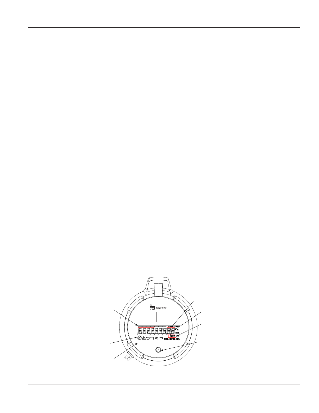
The HR-E LCD Encoder has a nine-digit Liquid Crystal Display (LCD) to show consumption, flow and alarm information.
There is no need to activate the display. The display automatically toggles between 9-digit and 6-digit consumption
(segmented leak detector in this mode), rate of flow and meter model.
Extended Visual
Reading Resolution
Typical Billing
Segments
HR
E LCD
In 6-digit mode, the
last digit is a dashed
line that becomes a
ow nder
Multiplier Value
(x10, x100, x1000, x10,000)
Status
Indicators
4-Digit
Date Code
1212
Figure 1: HR-E LCD Encoder Face
IR Programming
Port
Page 5 December 2012
Page 6
HR | E LCD Encoder
Visual Display
Units of Measure
The units of measure are factory-programmed and user-programmable. Options include U.S. gallons, Imperial gallons, cubic
feet, cubic meters, and liters.
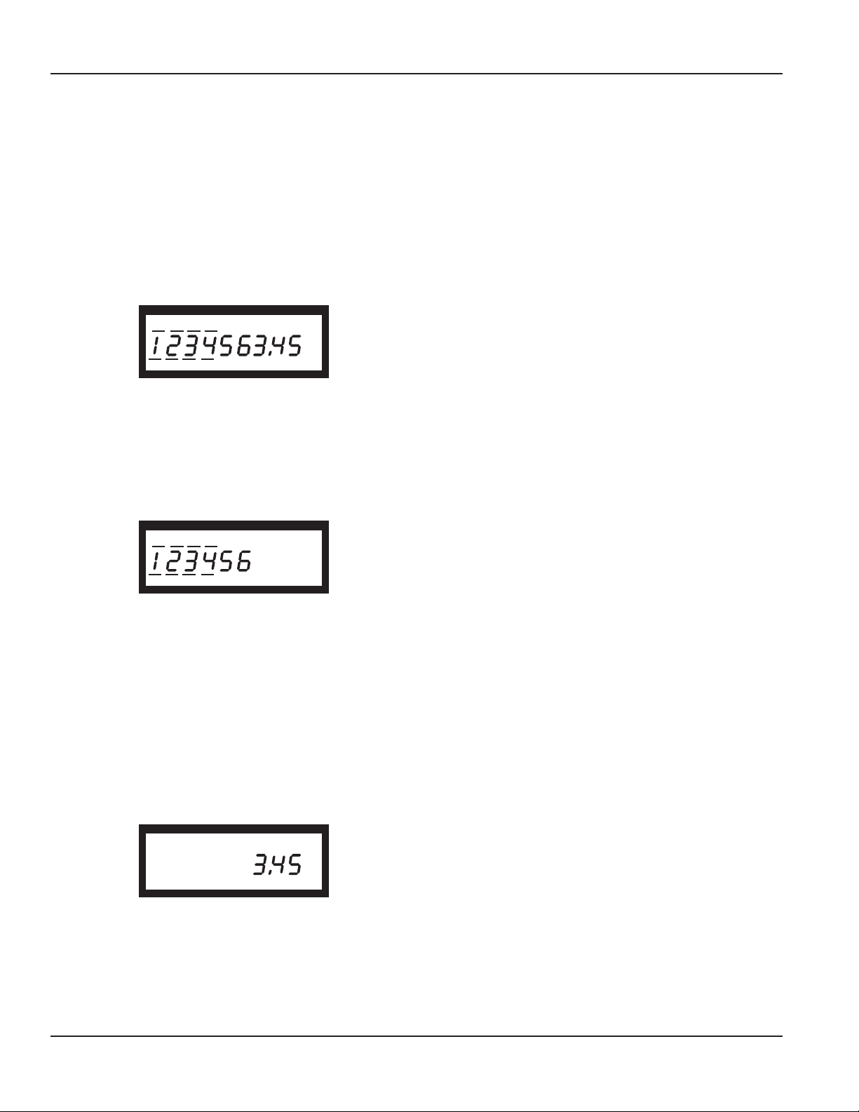
9-Digit Totalization
The consumption display includes all nine digits and a decimal point (based on meter model, size and unit of measure). The
displayed value is the sum of the forward flow minus any reverse flow. This screen displays for 30 seconds.
Model 25 Disc Series Meter Calibrated in Gallons
4
GAL
6-Digit Totalization
This mode is used to represent the typical 6 wheel odometer registration as seen on a mechanical encoder. In 6-digit totalizer
mode, depending on the meter model, size and unit of measure, one of the multiplier values will also be shown (X1, X10,
X100, X1000, X10,000). When water is flowing through the meter, this display will include a series of moving segments to
represent a flow finder. This screen displays for 20 seconds.
Model 25 Disc Series Meter Calibrated in Gallons
4
GAL
X10
In 9 and 6 digit totalizer mode, the display also includes indicator lines above and below the digits to provide the electronic
equivalent of the white and black number wheels seen on a mechanical encoder. The segmented lines above and below the
numbers represent what the white number wheels do for the mechanical encoders—typical utility standard billing units.
For more detailed information on the visual totalizer displays, see “How to Read and Encoder” document LCD-A-01.
Rate of Flow
The rate of flow is factory programmed for gallons per minute. The encoder displays both the unit of measure and rate of flow.
The rate of flow display is shown without leading zeros. A reverse flow is indicated by a minus sign before the flow rate. The
displayed rate will be based on the average flow rate for the prior minute (since the last time the flow rate was displayed). This
screen displays for 5 seconds.
Model 25 Disc Series Meter Calibrated in Gallons
4
RATE /MIN
Page 6 December 2012
GAL
Page 7
Installation and Programming Manual
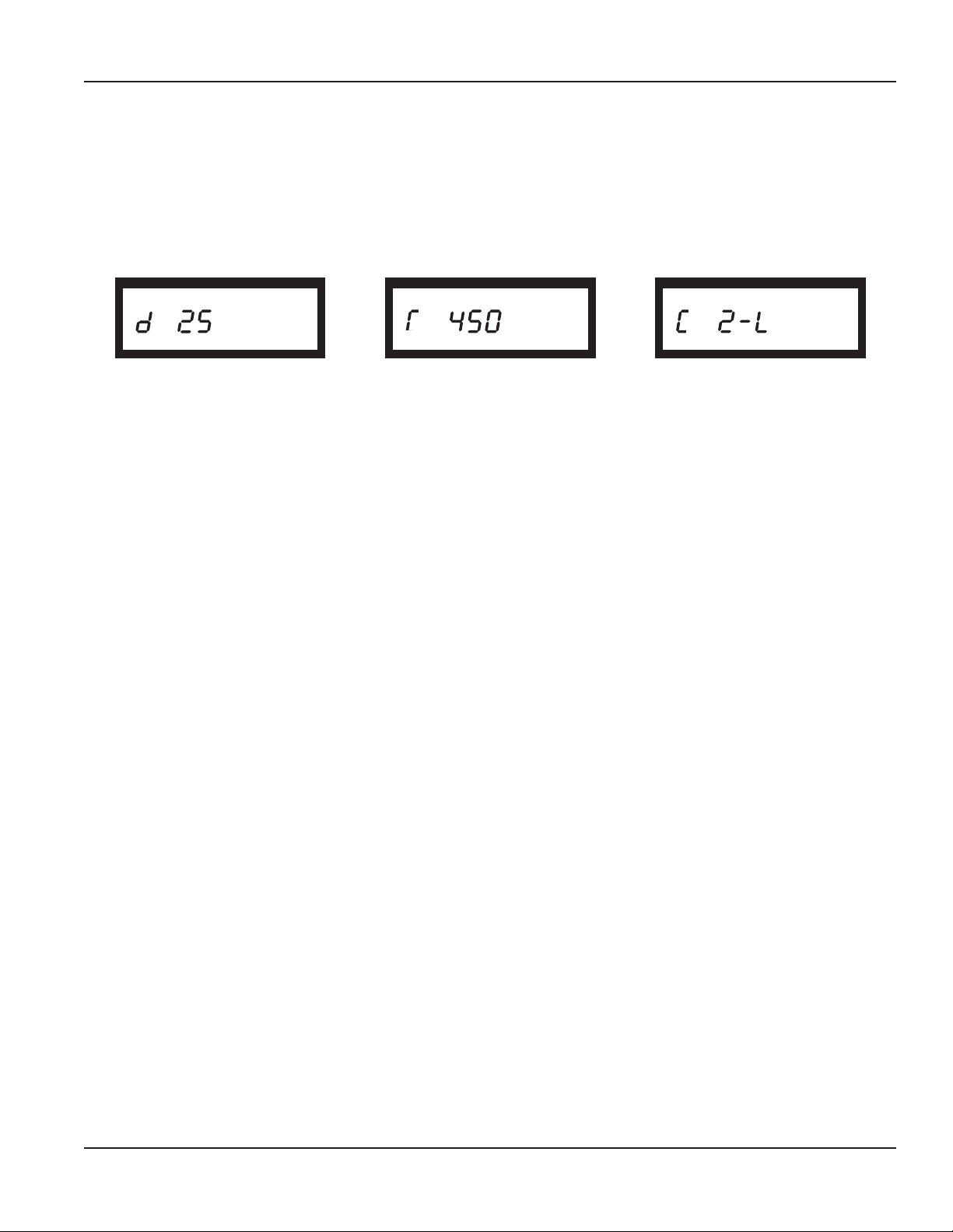
Meter Model Information
This screen identifies the meter for which the encoder was programmed and displays for 5 seconds. The display shows
the meter type (turbo, disc, compound), the meter model, and the unit of measure (gal, ft3, m3, imp, liter). Disc meters are
indicated by a d, Turbo meters are indicated by a stylized T (only the right half of the horizontal line appears) and Compound
meters are indicated by a C. See samples below:
Model 25 Disc Series Meter
Calibrated in Gallons
GAL GAL
Model 450 Turbo Series Meter
Calibrated in Gallons
2" Low Side Compound Series Meter
Calibrated in Cubic Feet
FT3
Page 7 December 2012
Page 8
HR | E LCD Encoder
Visual Measurement Resolution
Recordall
Disc Series
LP 5/8", 5/8" x 3/4" 0.01 0.001 0.0001
M25 5/8", 5/8" x 3/4" 0.01 0.001 0.0001
M35 3/4" 0.01 0.001 0.0001
M40 1" 0.01 0.001 0.0001
M55 1" 0.01 0.001 0.0001
M70 1" 0.01 0.001 0.0001
M120 1-1/2" 0.1 0.01 0.001
M170 2" 0.1 0.01 0.001
Recordall
Turbo Series
T160 1-1/2" 0.1 0.01 0.001
T200 2" 0.1 0.01 0.001
T450 3" 0.1 0.01 0.001
T1000 4" 0.1 0.01 0.001
T2000 6" 1 0.1 0.01
T3500 8" 1 0.1 0.01
T5500 10" 1 0.1 0.01
T6200 12" 10 1 0.01
T6600 16" 10 1 0.01
T10000 20" 10 1 0.01
Recordall Compound
Series
High Side T200 2" 0.1 0.01 0.001
Low Side M25 2" 0.01 0.001 0.0001
High Side T450 3" 0.1 0.01 0.001
Low Side M25 3" 0.01 0.001 0.0001
High Side T1000 4" 0.1 0.01 0.001
Low side M35 4" 0.01 0.001 0.0001
High Side T2000 6" 1 0.1 0.01
Low Side M35 6" 0.01 0.001 0.0001
High Side T3500 8" 1 0.1 0.01
Low side M120 8" 0.1 0.01 0.001
Size
Size
Size
Gallons Cubic Feet Cubic Meters
Gallons Cubic Feet Cubic Meters
Gallons Cubic Feet Cubic Meters
9-Digit Encoder Output
9-Digit Encoder Output
9-Digit Encoder Output
MPORTANTI
Endpoint Reading Resolution
The electronic encoder output resolution of the HR-E LCD Encoder is 9 digits. Though the encoder output is 9-digit resolution, the
reading resolution sent to the reading software is dependent on the endpoint that the HR-E LCD is connected to.
Readings reported from the endpoints are the left-most significant digits of the encoder reading.
Endpoint Technology Reading Resolution Reported to Reading Software
ORION ME/SE 8-digit reading, plus the extended message capability
ORION CE 7-digit reading
GALAXY 6-digit reading
See LCD-A-03-EN for appropriate test circle code/reading resolutions for the HR-E LCD encoder with ORION or GALAXY endpoints.
Page 8 December 2012
Page 9

Installation and Programming Manual
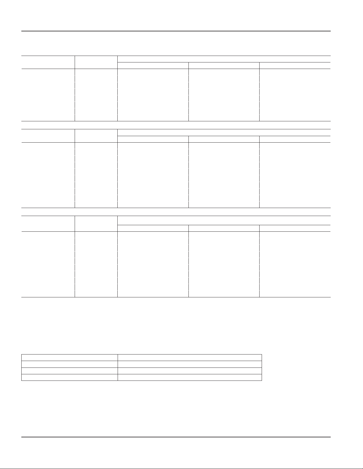
Status Indicators
Status indicators are sent as part of the encoder message to AMR/AMI systems that are capable of receiving an extended
message, such as ORION ME and SE endpoints. The details can also be read through an IR interface.
Status indicators appear in the display as symbols that illuminate when the condition is active and dim when the condition
is eliminated.
All HR-E LCD Encoders are delivered in a storage mode so that a meter alarm is not triggered. During storage mode, the meter
model displays on the encoder. As water begins to flow through the meter, the encoder switches from storage mode to
normal operation.
The following chart indicates the HR-E LCD Encoder conditions when connected to a Badger Meter ORION ME/SE endpoint.
The chart does not apply to ORION CE or GALAXY endpoints. The HR-E LCD displays the indicators and sends information, but
the ORION CE and GALAXY endpoints ignore the extra information and do not report it.
Status Indicator Icon Status Description HR-E LCD Display HR-E LCD with ORION ME/
SE *Version 1.8 or higher
firmware required
Meter
functioning
correctly
Encoder alarm Several potential conditions
Reverse flow Encoder detects reverse flow. Reverse flow alarm remains
Suspected leak Encoder detects 24 hours
Encoder operating correctly. Continuous display on
encoder as long as no other
status indicators are triggered.
Encoder alarm remains
may exist, including:
• Encoder removal
• Temperature limit
exceeded (34…140° F)
• Magnetic tamper
without one 15-minute
interval of no flow.
active for 35 days. The alarm
automatically clears after 35
days if any of the 3 conditions
has not recurred.
active for 35 days. The alarm
automatically clears after 35
days if reverse flow condition
has not recurred.
The alarm clears automatically
when a 15-minute no-flow
interval occurs
Indicator Status not sent to
the endpoint.
Encoder alarm sent to ORION
ME/SE endpoint.
Encoder detects reverse flow
and sends alarm message to
ORION ME/SE endpoint.
Encoder detects suspected
leak and sends alarm message
to ORION ME/SE endpoint.
30 day no usage No measured flow in past 30
days.
End of life
battery indicator
Indicated battery life based on
pre-calculated consumption.
The alarm is automatically
cleared once flow occurs.
Alarm activated at 19 years
and does not clear.
If condition clears before
message is sent to the
endpoint, it is not reported.
Encoder detects 30 days no
usage and sends alarm to
ORION ME/SE endpoint.
Encoder sends alarm to ORION
ME/SE endpoint.
Page 9 December 2012
Page 10

HR | E LCD Encoder
INSTALLING THE HRE LCD ENCODER
Bayonet Mount
The fully potted encoder assembly has a bayonet mount compatible with all Recordall Disc, Turbo Series, Compound Series,
Combo Series and Fire Series meters and assemblies. The bayonet mount positions the encoder in any of four orientations for
visual reading convenience. The HR-E LCD Encoder can be removed from the meter without disrupting water service.
The HR-E LCD Encoder is available factory pre-wired to Badger Meter AMR/AMI products. The HR-E LCD Encoder is
permanently sealed to eliminate the intrusion of moisture, dirt, or other contaminants, and is suitable for installation in all
environments, including meter pits subject to continuous submergence.
Install the encoder on the water meter and secure it using the tamper-proof screw provided.
Wire Connections
The HR-E LCD is provided as either a factory-wired assembly or as an encoder with pre-sized wire harness available for
connection in the field. Standardized lead lengths are 3, 10, 25, and 75 feet. See ADE-I-01 for instructions.
308 In-Line Connector
The Badger Meter 308 In-line connector is an optional feature that allows connectivity to a AMR/AMI devices without the
need for a field splice kit. See ORI-I-69 for instructions.
Page 10 December 2012
Page 11

HRE LCD ENCODER PROGRAMMING SOFTWARE
Installing the Program
This section describes how to install the HR-E LCD Encoder programming software.
1. Double-click the setup.exe le to begin installation. The Welcome screen displays.
Installation and Programming Manual
2. Click Next to select the destination folder for the program.
Page 11 December 2012
Page 12

HR | E LCD Encoder
3. Select a folder and click Next. An installation conrmation screen displays.
4. Click Next to conrm the installation. The program begins installing.
5. When the installation is complete, click Close to exit the installation program.
Page 12 December 2012
Page 13

Installation and Programming Manual
Launching the Program
1. Double-click the HR-E LCD Encoder desktop icon.
2. Read the License Agreement. If you agree, click Accept License. If you select Decline License, the program will
not start.
3. Once you accept the license agreement, the Splash screen displays. From this screen, you can view the license
agreement, view trademarks, and sign in. Your sign-in initials are used in the product’s log file to record any changes
you make to the HR-E LCD Encoder. To sign in, enter your initials using between 3 and 5 characters. After you enter
the third character, the Next button becomes active. Any characters after the 5th are ignored. When you have entered
your initials, click Next to display the Programmer screen.
Page 13 December 2012
Page 14

HR | E LCD Encoder
View License Option
The View License button displays a pop-up of the license agreement. The only option is to click Close to return to the
Splash Screen.
View Trademarks Option
The View Trademarks button displays a trademark pop-up specified by the Legal department. The only option is to click
Close to return to the Splash Screen.
Page 14 December 2012
Page 15

Installation and Programming Manual
CONNECTING THE HRE LCD ENCODER
To read and program the encoder using the Infrared Remote (IR) head, you must connect the IR head to a serial port on
your computer:
1. Plug the serial connector of the IR head into the serial port of your computer, or plug the serial connector of the IR
head into the serial-to-USB adapter, then plug the USB adapter into a USB port.
2. Open the lid on the encoder.
3. Mount the IR head bracket onto the encoder, aligning the hole in the holder with the IR port on the encoder.
4. Rest the IR head in the bracket with the nubs on the back of the head seated in the slots of the bracket.
Parts List
The 67660-001 kit includes:
67451-001 IR head bracket
67572-009 HR-E LCD Programming Software (not shown)
These optional parts are also available:
64436-023 IR programming and data profile cable
64436-029 Serial-to-USB Adapter
Page 15 December 2012
Page 16

HR | E LCD Encoder
PROGRAMMING THE HRE LCD ENCODER
From the Programmer screen, you can view and change the parameters that are currently programmed into the HR-E LCD
Encoder, as well as load new parameters into the HR-E LCD Encoder. You can also clear the encoder's reading.
Select the COM Port
The software communicates to the HR-E LCD Encoder via the selected COM Port. From the IR Port drop-down menu, select the
COM port connected to the encoder.
Perform a Read
Click on the Read option.
If the correct COM port is selected and a good response is received, the software delays a short time then populates the
Programmer screen data fields with the information from the encoder.
If the encoder is programmed the way you want, just disconnect it from the IR bracket. If not, see "Change Current Settings"
on page 17.
Page 16 December 2012
Page 17

Installation and Programming Manual
Read Errors
If no COM port is selected, this error message displays. In this case, click OK, select the correct COM port, and try the
Read again.
If the wrong COM port is selected, this error message displays. In this case, click Cancel, select the correct COM port, and try
the Read again.
Change Current Settings
If you need to change the settings for the current encoder, follow this procedure.
To set a default value for any of the data fields:
1. Click the down arrow to the right of the eld to display a drop-down list of values.
2. Click on the value you want to set as the default for that eld.
OTE:N You must set the default value for the Meter Type field before you set the Meter Model / Size field.
The Rate of Flow Units do not have to be the same as the Unit of Measure (even in a cubic foot meter, the
flow rate can be gallons per minute).
Apply Current Settings
When you click Apply Current Settings, the displayed settings are programmed into the encoder and the encoder goes into
storage mode. In storage mode, the encoder displays the meter type and unit of measure. In this example, a Model 25 Disc
Meter measured in gallons:
GAL
The software retains the current settings until you perform another Read.
If you have multiple encoders to program with the same parameters, just attach the IR head bracket to them, one at a time,
and click Apply Current Settings.
Page 17 December 2012
Page 18

HR | E LCD Encoder
HRE LCD PROGRAMMER PARAMETERS
Serial # Field
The Serial number field is a read-only field that displays the HR-E LCD Encoder factory-assigned serial number. You cannot
change this number.
12345
Meter Type Field
The Meter Type field displays the type of meter to which the encoder will connect.
Select the drop-down menu to the right of the data field to select the meter type. Available options are Disc, Compound
(CSM), Turbo (TSM).
Page 18 December 2012
Page 19

Installation and Programming Manual
Meter Model/Size Field
The Meter Model/Size field auto-populates based on the Meter Type selected.
Select the drop-down menu to the right of the data field to select a different meter model. The Meter Sizes corresponding to
the Meter Models in the drop-down menu are described in the table below.
For Recordall Combination Fire Service meters and assemblies, refer to the appropriate Disc and TSM columns of the table.
Disc Model CSM Model TSM Model
5/8", 5/8"x3/4" LP 2" High Side 1-1/2" T160
5/8", 5/8"x3/4" M25 2" Low Side 2" T200
3/4" M35 3" High Side 3" T450
1" M40 3" Low Side 4" T1000
1" M55 4" High Side 6" T2000
1" M70 4" Low Side 8" T3500
1-1/2" M120 6" High Side 10" T5500
2" M170 6" Low Side 12" T6200
16" T6600
20" T10000
Unit of Measure Field
The Unit of Measure field displays the unit selected to measure the flow.
Select the drop-down menu to the right of the data field to select a different unit of measure. The options are gallons, cubic
meter, liter, cubic feet, and Imperial gallons.
Page 19 December 2012
Page 20

HR | E LCD Encoder
Billing Units Field
The Billing Units field displays the default usage units for which the customer is billed. The defaults are based on the Unit of
Measure selected:
Unit of Measure Default Billing Unit
Gallons, liters, imperial gallons 1000
Cubic feet 100
Cubic meters 10
Select the drop-down menu to the right of the data field to select a billing unit.
Reading Field
The Reading field is a read-only field that displays the current meter reading as a real number. The number of decimal places is
determined by the units and meter size.
You cannot change this number.
Page 20 December 2012
Page 21

Installation and Programming Manual
Rate of Flow Units Field
The Rate of Flow Units field displays the unit by which the rate of flow is measured.
The factory-programmed default is Gallons.
Select the drop-down menu to the right of the data field to select a different rate of flow units. The options are gallons, cubic
meter, liter, cubic feet, and Imperial gallons.
Rate of Flow Time Field
The Rate of Flow Time field displays the time unit set for the rate of flow.
The factory-programmed default is Per Minute.
Select the drop-down menu to the right of the data field to select a different rate of flow time. The options are minutes, hours,
or seconds.
Page 21 December 2012
Page 22

HR | E LCD Encoder
View Indicators
The View Indicators button displays the current status of the selected meter.
The status indicators are Encoder Removal, 30 Day No Usage, Suspected Leak, Programmed, End of Battery Life, Reverse Flow,
Magnetic Tamper and Temperature Limit Exceeded. For descriptions of these indicators, see "Status Indicators" on page 9.
1. To clear the indicators, click the Clear Indicators button.
OTE:N The Clear Indicators button does NOT clear the Programmed indicator.
2. Click Close to exit the window.
Clear Reading
Be very careful with the Clear Reading feature! It deletes all readings for the selected meter. If you select this option, a pop-up
messages displays, asking you to enter a password to confirm the deletion.
Contact Badger Meter Technical Support to get the password.
Page 22 December 2012
Page 23

Installation and Programming Manual
TROUBLESHOOTING
Issue Probable Cause Solution
Programmer screen is blank after a
Read.
Error message displayed after clicking
an option on the programmer screen.
Bad connection. Check for damaged or broken wires.
COM Port not specied. Select a COM Port from the IR Port
drop-down menu.
IR head not aligned with encoder. Align the IR head with the IR port on
the encoder.
UPDATING THE FIRMWARE VERSION OF ADE TYPE ME/SE ENDPOINTS
For the HR-E LCD, ME/SE endpoints need to be high resolution version endpoints.
This procedure should be used only for updating the rmware version of in-stock stand-alone encoder type “ADE” ME/
SE endpoints.
Firmware version 1.9 or higher is required in these endpoints to use the HR-E LCD encoder. The Attach Endpoints feature
updates the rmware version of the endpoint.
To update the rmware version of an ADE type ME/SE endpoint:
1. Align and hold the IR head over the antenna at the bottom of the endpoint.
2. Click the Attach Endpoint button.
If the endpoint is properly aligned to the IR head, the programmer queries the endpoint, then updates its rmware version.
If the programmer cannot find the endpoint, it displays this message:
In this case, reposition the IR head so it contacts the antenna on the
endpoint, then click OK.
Page 23 December 2012
Page 24

ADE, GALAXY, ORION, RECORDALL, and RTR are registered trademarks of Badger Meter, Inc. Other trademarks appearing in this document are the property of their respective entities.
Due to continuous research, product improvements and enhancements, Badger Meter reserves the right to change product or system specications without notice, except to the extent an outstanding
contractual obligation exists. © 2012 Badger Meter, Inc. All rights reserved.
www.badgermeter.com
The Americas | Badger Meter | 4545 West Brown Deer Rd | PO Box 245036 | Milwaukee, WI 53224-9536 | 800-876-3837 | 414-355-0400
México | Badger Meter de las Americas, S.A. de C.V. | Pedro Luis Ogazón N°32 | Esq. Angelina N°24 | Colonia Guadalupe Inn | CP 01050 | México, DF | México | +52-55-5662-0882
Europe, Middle East and Africa | Badger Meter Europa GmbH | Nurtinger Str 76 | 72639 Neuffen | Germany | +49-7025-9208-0
Czech Republic | Badger Meter Czech Republic s.r.o. | Maříkova 2082/26 | 621 00 Brno, Czech Republic | +420-5-41420411
Slovakia | Badger Meter Slovakia s.r.o. | Racianska 109/B | 831 02 Bratislava, Slovakia | +421-2-44 63 83 01
Asia Pacific | Badger Meter | 80 Marine Parade Rd | 21-04 Parkway Parade | Singapore 449269 | +65-63464836
China | Badger Meter | Rm 501, N° 11 Longyue Apartment | N° 180 Longjin Rd, Jiuting Songjiang District | Shanghai, China | 201615 | +86-21-5763 5412
 Loading...