

Page 1

Instruction 19-9201
Rev. 3 – June 1999
®
Snif it Model 50
Carbon Monoxide Analyzer
Introduction
Designed for HVAC professionals and utility personnel, the Snifit Model 50 Analyzer is ideal for measuring low levels of CO in ambient air such as in rooms
and garages, or around registers, furnaces, stoves,
water heaters, and other types of combustion appliances. The Snifit samples the surrounding air and
shows the detected concentration of CO on its Liquid
Crystal Display. The Snifit is not intended to be used in
flue gases or in temperatures exceeding 104 °F (40 °C).
Features
• Measures and displays 0 to 1999 ppm CO in room air
• Sensitive CO sensor will last up to 2 years
• Backlight for viewing in dark areas
• Compact pocket size
• Low battery indication
• Manual zero adjust
• Factory calibrated on 100 ppm CO
• Simple field calibration
• Auto power-off after 35 minutes
• Single 9V battery (included) provides at least
1500 hours of operation
621 Hunt Valley Circle, New Kensington, PA 15068
Ph: 724-334-5000 • Fax: 724-334-5001 • Toll Free: 800-736-4666
Website: www.bacharach-inc.com • E-mail: help@bacharach-inc.com
Printed in U.S.A. ® Registered trademarks
Bacharach, Inc.
Page 2
Specifications
Gas Monitored ............Carbon Monoxide (CO)
Range ..........................0 to 1999 ppm
Resolution ...................1 ppm
Accuracy......................± (5% of reading + 5 ppm)
Response .....................≤30 sec. to 90% of final value
Power...........................9V battery
Battery Life ................1500 hours minimum
Temperature Range ....32 to 104 °F (0 to 40 °C)
Case Material .............High impact plastic
Weight.........................0.25 lb (0.11 kg) without battery
Dimensions .................5.5" L x 2.0" W x 1.6" H
(140 x 51 x 41 mm)
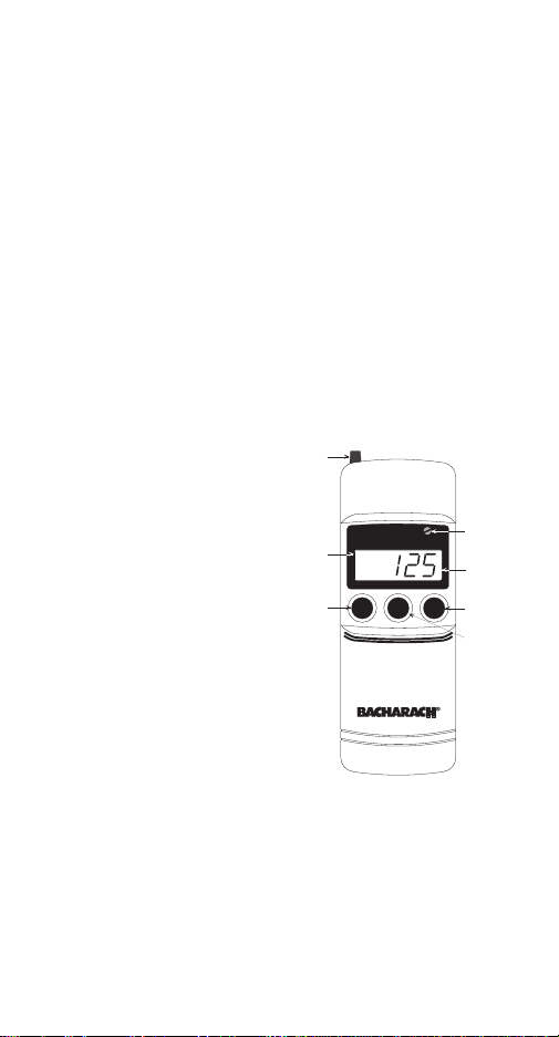
Operation
Turning the Snifit
On/Off
If not already done,
install a 9V battery as
described under
Battery Installation.
Turn on the instrument by pressing its
Power On button.
ZER O
ADJUST
LO W
BATTE RY
IN D IC A T IO N
BACKLIGH T
ON/OFF
CARBON
S n if it
M O NO XIDE ANALYZER
m odel 50
Span Adjust
LO BAT
-Power-
Backlight
Off
ppm CO
On
SPAN
ADJUST
POT.
DISPLAY
POW ER ON
POW ER OFF
Turn it off by pressing
Power Off (or the
instrument will
automatically shut
itself off after approximately 35 minutes).
Figure 1. Snifit 50
Zeroing the Sensor
Turn on the Snifit and allow the displayed reading to
stabilize before proceeding – approximately 30 seconds. Then with the instrument sampling fresh air
- 2 -
Page 3

(air that is free of CO), adjust the Zero Adjust knob at
the top of the instrument for a reading of 0 ±1 ppm.
If you’re not sure about the quality of the surrounding
air, you can apply a blend of Oxygen/Nitrogen gas to
the sensor as described under Calibration.
Checking for CO
Important! Ensure that the sensor grille at the rear of
the instrument is unobstructed and open to the atmosphere. A quick instrument check can be performed by
allowing the smoke of a blown-out match to enter into
the sensor grille. This should cause the indicated CO
level to increase.
After zeroing the Snifit, simply hold the instrument in
the area that you suspect the presence of CO gas. If
CO is present, the instrument will indicate the
concentration of CO in ppm on its display.
Backlight
Pressing the Backlight button will illuminate the
display for a period of 8 minutes, or until it is manually turned off by again pressing the Backlight button.
Overrange
If the CO level exceeds 1999 ppm, the
displayed reading is replaced by the
number “1”.
Low Battery
When the Snifit’s 9V battery is
nearing the end of its useful life,
LO BAT will appear in the upper left
hand corner of the display. Although
you can continue using the instrument under this
condition, you should replace the battery as soon as
possible to ensure accurate CO readings.
- 3 -
LO B AT
Page 4

234
1
Parts Shown:
1. C O Span G as Cylinder, 51-1994
2. R egulator, 03-4318*
3. Tubing, 03-6351*
4. Flow m eter, 06-6163*
5. C alibration C up Assem bly, 23-2156**
* P a rt o f C a lib ra tio n K it 24 -7 05 9
** Part of Tool / C up Kit 19-3242
PUSH C ALIBRATION CU P
OVER SENSOR HOUSING
5
Figure 2. Calibration Equipment Setup
Calibration
Important! For accurate Snifit operation, periodic
calibration of its CO sensor is required.
To calibrate the CO sensor, you will need the equipment listed under Accessories. Note that the Zero Gas
Cylinder is needed only if you’re unsure about the
quality of the surrounding air for zeroing purposes.
Calibrate the sensor to a known concentration of CO
gas as follows:
1. Assemble the calibration equipment per Figure 2.
2. Zero the instrument as previously described under
Zeroing the Sensor.
If necessary, you can use the calibration cup to apply
a blend of Oxygen/Nitrogen gas directly over the
sensor by attaching a zero gas cylinder to the
regulator and adjusting the regulator knob for a
flow rate of 2 SCFH.
3. Push the Calibration Cup over the sensor housing.
4. Attach a CO Span Gas Cylinder to the regulator.
Then apply span gas to the sensor by adjusting the
regulator knob for a flow rate of 2 SCFH.
- 4 -
Page 5

5. Allow span gas to flow until the displayed reading
stabilizes – approx. 3 minutes. Then, using Calibration Tool 06-9453 (supplied in Calibration Tool /
Cup Kit 19-3242), turn the Span Adjust potentiom-
eter until the displayed reading matches the
concentration stamped on the Span Gas Cylinder.
6. Calibration is now complete. Turn off the Regulator
and remove the calibration equipment.
Maintenance
Battery Installation
Remove the slotted screw from
the rear of instrument; then
lift off the front case.
Install a 9V Alkaline battery
(Duracell MN1604 or equiv.) in
the location shown in Figure 3;
then reinstall the front case.
Sensor Replacement
The sensor needs replaced when it can no longer be
calibrated to the Span Gas Cylinder value using the
Span Adjust potentiometer.
Figure 3. Battery
Location
1. See Figure 4. Remove the screw from the rear of the
instrument; then lift off the front case and remove
the printed circuit board assembly.
2. Unplug the old sensor and dispose of it properly.
3. Inspect the sensor gasket and filter. Replace an
item if is torn, deformed, or contaminated with dirt.
4. Remove the wire-jumper from the pins of the new sensor;
plug in the sensor; then reassemble the instrument.
5. Calibrate the new sensor.
- 5 -
Page 6

CO
SENSO R
W ARNING!
Remove
ju m p e r-w ire
fro m p in s b e fo re
in s ta lla tio n
Figure 4. Sensor Installation
FILTER
GASKET
Replacement Parts
Item Part No.
CO Sensor .......................................................... 19-7061
Gasket ................................................................ 19-3234
Filter .................................................................. 19-3244
Accessories
Item Part No.
Calibration Kit .................................................. 24-7059
Calibration Tool / Cup Kit................................ 19-3242
Span Gas Cylinder, 100 ppm CO in air........... 51-1994
Zero Gas Cylinder, 20.9% O2 in Nitrogen ....... 51-7131
Bacharach Service Center
Replacement parts and accessories can be obtained by
contacting the following Bacharach Service Center:
Bacharach, Inc.
625 Alpha Drive
Pittsburgh, PA 15238
Phone: (412) 963-2214
FAX: (412) 963-2606
- 6 -
 Loading...