

Page 1
Portable Combustion
Analyzer (PCA)
INSTRUCTION 24-9351
Operation & Maintenance
Rev. 11 – May 2004
O 2 4 . 0 C O 1 2 H L D
C 2 9 . 5 C U 1 5 N G
T L 2 0 . 0 T A 1 9 0 P
q A 8 . 1 L A 1 . 2 4 S
M E N U
P C A
Product Leadership • Training • Service • Reliability
Page 2

WARRANTY
Bacharach, Inc. warrants to Buyer that at the time of delivery this Product will be free from defects
in material and manufacture and will conform substantially to Bacharach Inc.’s applicable
specifications. Bacharach’s liability and Buyer’s remedy under this warranty are limited to the
repair or replacement, at Bacharach’s option, of this Product or parts thereof returned to Seller at
the factory of manufacture and shown to Bacharach Inc.’s reasonable satisfaction to have been
defective; provided that written notice of the defect shall have been given by Buyer to Bacharach
Inc. within one (1) year after the date of delivery of this Product by Bacharach, Inc.
Bacharach, Inc. warrants to Buyer that it will convey good title to this Product. Bacharach’s
liability and Buyer’s remedy under this warranty of title are limited to the removal of any title
defects or, at the election of Bacharach, to the replacement of this Product or parts thereof that
are defective in title.
THE FOREGOING WARRANTIES ARE EXCLUSIVE AND ARE GIVEN AND ACCEPTED IN
LIEU OF (I) ANY AND ALL OTHER WARRANTIES, EXPRESS OR IMPLIED, INCLUDING
WITHOUT LIMITATION THE IMPLIED WARRANTIES OF MERCHANTABILITY AND FITNESS
FOR A PARTICULAR PURPOSE: AND (II) ANY OBLIGATION, LIABILITY, RIGHT, CLAIM OR
REMEDY IN CONTRACT OR TORT, WHETHER OR NOT ARISING FROM BACHARACH’S
NEGLIGENCE, ACTUAL OR IMPLIED. The remedies of the Buyer shall be limited to those
provided herein to the exclusion of any and all other remedies including, without limitation
incidental or consequential damages. No agreement varying or extending the foregoing
warranties, remedies or this limitation will be binding upon Bacharach, Inc. unless in writing,
signed by a duly authorized officer of Bacharach.
Register Your Warranty by Visiting
www.bacharach-inc.com
PCA
Notice:
Product improvements and enhancements are continuous, therefore the specifications and information
contained in this document may change without notice.
Bacharach, Inc. shall not be liable for errors contained herein or for incidental or consequential damages in
connection with the furnishing, performance, or use of this material.
No part of this document may be photocopied, reproduced, or translated to another language without the prior
written consent of Bacharach, Inc.
Copyright © 1999–2004, Bacharach, Inc., all rights reserved.
BACHARACH is a registered trademark of Bacharach, Inc. All other trademarks,
trade names, service marks and logos referenced herein belong to their respective companies.
A
Instruction 24-9351
Page 3

PCA
Contents
Contents
1.0 INTRODUCTION ............................................................................ 1-1
1.1 The Portable Combustion Analyzer........................................... 1-1
1.2 Displayed Data ........................................................................... 1-2
1.3 Sensor Configurations ................................................................ 1-3
2.0 TECHNICAL CHARACTERISTICS ............................................ 2-1
3.0 SETTING UP THE PCA................................................................. 3-1
3.1 Scope........................................................................................... 3-1
3.2 Power.......................................................................................... 3-1
3.2.1 Checking and Replacing the Batteries ........................... 3-1
3.2.2 Using the Optional Power Supply .................................. 3-2
3.3 Connecting the Probe ................................................................ 3-2
3.4 Configuring the PCA ................................................................. 3-4
4.0 OPERATION.................................................................................... 4-1
4.1 Key Pad Functions..................................................................... 4-1
4.2 Sampling Hole Location ............................................................ 4-2
4.3 Combustion Test ........................................................................ 4-3
4.3.1 Analyzer Turn On and Warm Up .................................. 4-3
4.3.2 Installing Probe in the Stack ......................................... 4-4
4.3.3 Performing a Combustion Test ...................................... 4-5
4.3.4 Ending a Combustion Test............................................. 4-5
4.3.5 Turning Off the Analyzer and Purging the CO Sensor.... 4-6
4.4 Differential Pressure Measurement ......................................... 4-7
4.5 Warm-up Screen ........................................................................ 4-8
4.6 Sensor Status Screen................................................................. 4-9
4.7 Combustion Test Screen.......................................................... 4-10
4.8 Fuel Selection Screen .............................................................. 4-11
4.9 Draft Screens ........................................................................... 4-12
4.10 Memory Directory Screen ..................................................... 4-13
4.11 Memory to PC Screen ............................................................ 4-14
4.12 ID Setup Screens ................................................................... 4-17
4.13 Temperature Setup Screen ................................................... 4-19
4.14 Draft Unit Setup Screen ....................................................... 4-20
4.15 Language Setup Screen......................................................... 4-21
4.16 Display Mode Setup Screen .................................................. 4-22
4.17 Time/Date Setup Screen........................................................ 4-23
4.18 Printer Setup Screen ............................................................. 4-24
4.19 Maintenance Password Screen ............................................. 4-25
4.20 Maintenance Screen .............................................................. 4-26
4.21 User Name Screens ............................................................... 4-27
Instruction 24-9351
i
Page 4

Contents
PCA
4.22 Saving Test Data ................................................................... 4-28
4.23 Printing Test Data................................................................. 4-29
4.24 Clear Memory Screen ............................................................ 4-31
4.25 Resetting the Microprocessor................................................ 4-31
5.0 CALIBRATION................................................................................ 5-1
5.1 Sensor Check ............................................................................. 5-1
5.2 Calibration Fixtures .................................................................. 5-2
5.3 Calibrate Menu Screen.............................................................. 5-3
5.4 Calibrate TA-Zero...................................................................... 5-4
5.5 Calibrate TA-Span..................................................................... 5-5
5.6 Calibrate TL-Zero ...................................................................... 5-6
5.7 Calibrate TL-Span ..................................................................... 5-7
5.8 Calibrate NX .............................................................................. 5-8
5.9 Calibrate CO .............................................................................. 5-9
5.10 Calibrate Draft....................................................................... 5-11
6.0 MAINTENANCE.............................................................................. 6-1
6.1 Routine Maintenance ................................................................ 6-1
6.2 Disassembly ............................................................................... 6-2
6.3 Cleaning the Probe .................................................................... 6-4
6.4 Water Trap/Filter Assembly Maintenance............................... 6-5
6.5 Replacing the Particulate Filter ............................................... 6-6
6.6 Replacing the Oxygen Sensor ................................................... 6-7
6.7 Replacing the Nitric Oxide Sensor ........................................... 6-8
6.7.1 Replacing the Nitric Oxide Sensor Filter ...................... 6-8
6.7.2 Replacing the Nitric Oxide Sensor Bias Battery .......... 6-9
6.8 Replacing the Carbon Monoxide Sensor................................. 6-10
6.8.1 Replacing the Carbon Monoxide Sensor Filter ........... 6-11
6.9 Replacing the Pump Assembly ............................................... 6-12
7.0 TROUBLESHOOTING.................................................................... 7-1
7.1 Analyzer Repair ......................................................................... 7-1
7.2 Error Codes ................................................................................ 7-2
7.3 Troubleshooting Guide .............................................................. 7-3
8.0 PARTS & SERVICE........................................................................ 8-1
8.1 Replacement Parts..................................................................... 8-1
8.2 Accessories ................................................................................. 8-2
8.3 Sales/Service Centers ................................................................ 8-6
APPENDIX A – Display Screen Translations...................................A-1
APPENDIX B – Printout Translations ..............................................B-1
ii
Instruction 24-9351
Page 5
PCA
Introduction
1.0 INTRODUCTION
1.1 The Portable Combustion Analyzer
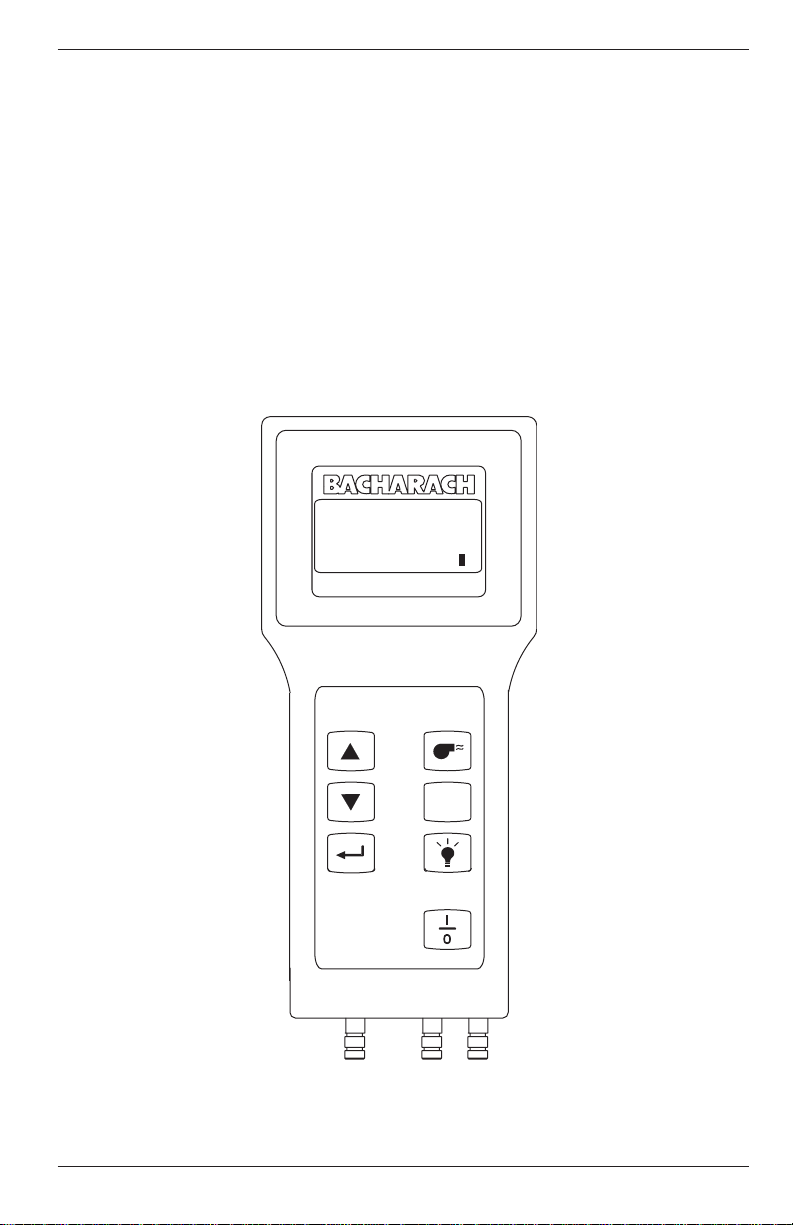
The Portable Combustion Analyzer (PCA) (Figure 1-1) is a commercial
grade, hand held, combustion efficiency analyzer that is designed for
continuous (on demand) sampling of light industrial and residential
furnaces, appliances, and boilers. The basic instrument is supplied with a
probe, instruction manual, batteries, and carrying case.
O 2 4 . 0 C O 1 2 H L D
C 2 9 . 5 C U 1 5 N G
T L 2 0 . 0 T A 1 9 0 P
q A 8 . 1 L A 1 . 2 4 S
Instruction 24-9351
M E N U
P C A
Figure 1-1. PCA
1-1
Page 6

Introduction
PCA
1.2 Displayed Data
The PCA directly measures, displays, and stores the following data:
• Room Temperature in °C or °F (Primary Air/Ambient Temperature)
• Flue Gas Oxygen Content in %
• Flue Gas Temperature in °C or °F
• Flue Gas Carbon Monoxide Content (H2 Compensated) in ppm
(For analyzers having a Carbon Monoxide sensor)
• Flue Gas Nitric Oxide content in ppm
(For analyzers having a Nitric Oxide sensor)
• Pressure/Draft in Millibars, Pascals, or Inches of Water Column
(For analyzers having a draft sensor)
• Differential Pressure in Millibars, Pascals, or Inches of Water Column
(For analyzers having a draft sensor)
The PCA will compute, display, and store the following data for any of the
standard fuels:
• Stack Loss in %
• Lambda
• Flue Gas Carbon Dioxide Content in %
• Flue Gas Carbon Monoxide Content referenced to 0% Oxygen in ppm
(For analyzers having a Carbon Monoxide sensor)
• Flue Gas Nitric Oxide Content referenced to 0% Oxygen in ppm
(For analyzers having a Nitric Oxide sensor)
The standard fuels are:
• Natural Gas
• Oil #2
• Oil #6
• LPG
• Koks
• Low Energy Gas
• P-Coal (available in English, German, Dutch, French, Italian,
Polish, and Spanish languages)
• Biofuel (available in Danish, Finnish, and Swedish languages)
The PCA continuously monitors flue-gas-exhaust conditions and updates
the above displayed values during a combustion test. If the analyzer is
equipped with an optional pressure sensor, draft measurements can be
made simultaneously with the combustion test, or made separately.
The analyzer has the ability to store data that was collected during a
combustion test or draft measurement. The stored data can then either be
viewed on the PCA’s display, printed using an optional printer, or downloaded to a computer.
1-2
Instruction 24-9351
Page 7

PCA
Introduction
1.3 Sensor Configurations
TABLE 1-1. PCA SENSOR CONFIGURATIONS
PCA Models Sensors Installed
Standard Advanced
PCA Part No.* Part No.** PCA Part No.* Part No.** Stack Temp., CO NX Draft
Model 24- 24- Model 24- 24- Air Temp. & O
10 7181 7281 40 7241 7251 X
15 7182 7282 45 7242 7252 X X
20 7183 7283 50 7243 7253 X X
25 7184 7284 55 7244 7254 X X X
30 7185 7285 60 7245 7255 X X X
35 7186 7286 65 7246 7256 X X X X
* English, Danish, Dutch, German, Finnish & Swedish languages
** English, French, German, Italian, Polish & Spanish languages
2
PCA 10 & 40
These basic instruments have the capability of measuring, displaying,
and storing combustion tests. They will also display flue gas Oxygen
content, flue gas Carbon Dioxide (CO2) content, air temperature, flue gas
temperature, stack loss, Lambda, and the current fuel selected. The
‘standard’ PCA 10 stores up to 10 combustion tests, while the ‘advanced’
PCA 40 can store up to 100 tests.
(
∆∆
∆P)
∆∆
PCA 15 & 45 with Draft
In addition to the features of the basic PCAs described above, these instruments have the added capability of measuring, displaying, and saving draft
or differential pressure in either Millibars, Pascals, or Inches-of-Water
Column.
PCA 20 & 50 with Carbon Monoxide Measurement
In addition to the features of the basic PCAs described above, these
instruments have the added capability of measuring, displaying, and
saving Carbon Monoxide (CO) content, as well as calculating CO referenced to 0% Oxygen.
PCA 25 & 55 with Draft and CO Measurement
These instruments combine the features of all the PCAs listed above.
PCA 30 & 60 with CO and Nitric Oxide Measurement
In addition to the features of the basic PCAs with CO measurement, these
instruments have the added capability of measuring, displaying, and
saving Nitric Oxide (NX) content, as well as calculating NX referenced to
0% Oxygen.
Instruction 24-9351
1-3
Page 8

Introduction
PCA
PCA 35 & 65 with Draft, CO & NX
These instruments are capable of measuring, displaying, and saving all
measurements as previously described.
Printout Capability
All PCAs have the ability to print the latest test data, or any of the saved
tests, to an optional printer using HP, IrDA or RS-232 protocol.
Advanced PCA Model Features
‘Advanced’ models of the PCA contain the following features that are in
addition to the features of their corresponding ‘standard’ PCAs:
• 100 memory locations
• RS232 output for transferring saved data to a Personal Computer
• Ability to enter three lines of user-identification information that is
printed at the top of each printout
• Ability to enter three lines of customer-identification information that
is printed with each test record.
• Automatic CO sensor purge on analyzers equipped with a CO sensor
Instruction 24-93511-4
Page 9

PCA
Technical Characteristics
2.0 TECHNICAL CHARACTERISTICS
The PCA Directly Measures and Displays:
• Oxygen content in flue gas in the range of 0.1 to 20.9 % O
• Flue gas temperature in the range of –18 to 1200 ºC (0 to 2192 ºF)
• Primary-air / ambient temperature is in the range of –18 to 999 ºC
(0 to 999 ºF)
Optional . . .
• Differential pressure/draft in the range of ±70.0 mb (±28" H2O)
• Carbon Monoxide* content in flue gas in the range of 0 to 4000 ppm
• Nitric Oxide* content in flue gas in the range of 0 to 1000 ppm
The PCA Computes and Displays:
(When the measured oxygen level is not above 18.8%, and the Stack (Flue
Gas) temperature is not above 1200 ºC (2192 °F)
• Stack loss in the range of 0.1 to 99.9%
• Carbon Dioxide content in flue gas from 0.1 to a fuel dependent
maximum value in percent
• Lambda in the range of 1 to 9.95
• Carbon Monoxide* content referenced to 0% Oxygen in the range of
0 to 9,999 ppm on analyzers equipped with a CO sensor.
• Nitrix Oxide* content referenced to 0% Oxygen in the range of 0 to
9,999 ppm on analyzers equipped with a NX sensor.
2
Standard Fuels** Available for
Combustion Calculations:
• Natural Gas
• Koks
• LEG
• LPG
• Oil #2
• Oil #6
• P-Coal (available in English, German, Dutch, French, Italian,
Polish, and Spanish languages)
• Biofuel (available in Danish, Finnish, and Swedish languages)
* For the PCA 30, 35, 60, & 65, the display can be set up to show either
measured values of Carbon Monoxide and Nitric Oxide (CO & NX), or
show the calculated values of these gases (CU & NU) referenced to
0% Oxygen. In either case, all values are listed on the printout of
analzyers equipped with a printer.
** Custom fuels available upon request. Contact factory for details.
Instruction 24-9351
2-1
Page 10

Technical Characteristics
Normal Operating Conditions:
Temperature:
Analyzer ...................0 to 40 ºC (32 to 104 ºF)
Probe.........................800 ºC (1472 ºF) Max.
Humidity:
Analyzer ...................15 to 90% Relative Humidity, Non-Condensing
Air Pressure:
Analyzer ...................Atmospheric
Probe.........................25 mb (10" H2O) draft max at probe tip
Performance:
Accuracy:
Oxygen*....................±0.3% O
Carbon Monoxide.....±5% of reading or ±10 ppm, whichever is greater
between 0 – 2000 ppm, and ±10% of reading
between 2001 – 4000 ppm.
Nitric Oxide..............±5% of reading or ±5 ppm, whichever is greater
Flue Gas Temp......... ±2 ºC between 0 and 124 ºC
±3 ºC between 125 and 249º C
±4 °C between 250 and 400 °C
Ambient Temp. ........±1 °C between 0 and 100° C
Pressure ...................±2% of reading or ±0.05 mb (±0.02 inches of
Water Column), whichever is greater
2
(±4 ºF between 32 and 255 ºF)
(±6 ºF between 256 and 480 ºF)
(±8 ºF between 481 and 752 ºF)
(±2 ºF between 32 and 212 ºF)
PCA
System Flow Rate:
With probe................200 cc/min minimum
Front Panel Controls:
Seven embossed push-button switches with tactile feedback (refer to
Section 4.1)
* Accuracy referenced in practical flue gas concentrations
(mixtures of O2, CO2 and N2)
2-2
Instruction 24-9351
Page 11

PCA
Technical Characteristics
Display:
20 character by 4 line alphanumeric LCD panel with a green backlight.
Power Requirements:
Four disposable AA alkaline batteries. Battery backup for the real-time
clock, RAM, and bias voltage for the Nitric Oxide sensor are provided by
internal lithium batteries. Optional AC Power Supplies (110 VAC &
230 VAC) are also available.
Operating Time:
A fresh set of four disposable AA alkaline batteries provides at least
8 hours of continuous operation with the pump running and the backlight
turned on.
Warm Up Time:
60 seconds.
Printer Interface:
Infrared & RS-232 Communications (refer to Section 4.23).
Materials:
• High impact ABS plastic case
• Polycarbonate window over the display
• Nickel plated, brass quick-connect hose fitting
• Stainless steel probe
Dimensions:
Height:.................. 215 mm (8.5 in.)
Width: ................... 96 mm (3.8 in.) at display (75 mm [3.0 in.] at controls)
Depth:................... 50 mm (2 in.)
Weight:
With Batteries:..... Approximately 0.7 Kg (1.5 lbs)
Instruction 24-9351
2-3
Page 12

Technical Characteristics
Agency Approvals:
_ TÜV Agency Approved (1.BImSchV - First Ordinance of the German
Federal Emissions Law)
Approval Number: TÜV By RgG 168
_ CE declaration of conformity
Manufacturer's name: Bacharach, Inc.
Manufacturer's address: 621 Hunt Valley Circle
New Kensignton, PA 15068
European operations: Bacharach Instruments
Sovereign House, Queensway
Royal Leamington Spa
Warwickshire CV31 3JR
United Kingdom
Product name: Portable Combustion Analyzer (PCA)
conforms to the following CE
requirements:
EN 50081-1, January 1992 (Emissions)
EN 50082-1, January 1992 (Immunity)
Equations
PCA
2
×=
max
COC2
()
TLTAqA
21
=
LA
2
−
O21
×=
COCU
×=
NONU
2-4
2
O21
−
21
21
2A
×−=
21
−
−
O21
O21
2
−
()
O21
2
2
Where:
= Measured Oxygen in percent
O
2
TA = Measured stack temperature in °C
TL = Measured primary air temperature in °C
CO = Measured Carbon Monoxide in ppm
+
B
NO = Measured Nitric Oxide in ppm
C2 = Calculated Carbon Dioxide in percent
qA = Calculated stack loss in percent
LA = Calculated Lambda
CU = Calculated Carbon Monoxide referenced
to 0% Oxygen
NU = Calculated Nitric Oxide referenced to 0%
Oxygen
CO2max, A2, and B are constants (see below)*:
Fuel CO2max A2 B
NG 11.8 0.66 0.009
KOKS 10.2 0.60 0.011
LEG 13.1 0.63 0.011
LPG 13.8 0.63 0.008
Oil#2 15.4 0.68 0.007
Oil#6 15.9 0.68 0.007
P-Coal 18.7 0.60 0.007
Biofuel 20.4 0.70 0.012
* Some constants vary for Danish, Italian, and Polish fuels
Instruction 24-9351
Page 13
PCA
Setup
3.0 SETTING UP THE PCA
3.1 Scope
Before using the PCA, you MUST:
• Check the batteries or plug in an optional Power Supply (Section 3.2)
• Connect the probe to the analyzer (Section 3.3)
• Check the analyzer’s configuration (Section 3.4)
3.2 Power
3.2.1 Checking and Replacing the Batteries
A fresh set of batteries is supplied with the PCA. Install the batteries as
described below. Check for a sufficient charge prior to each use. If a
LOWBATTERY message is displayed, replace the batteries.
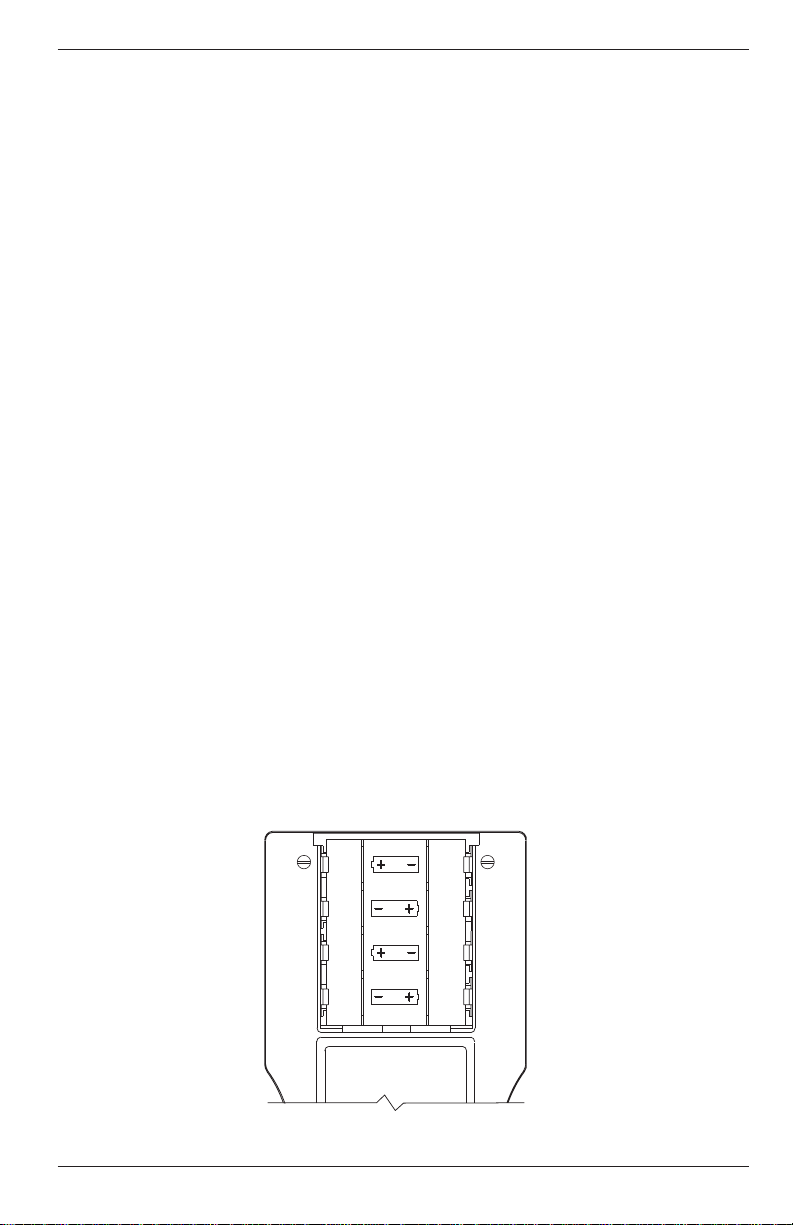
1. Remove the battery cover from the back of the PCA (Figure 3-1).
2. Remove (and properly dispose of) the old batteries.
3. Install a new set of four AA alkaline batteries, making sure to properly orient them as indicated by the “+” and “–” terminals in the
battery compartment.
4. Replace the battery cover.
Figure 3-1. Battery Replacement
Instruction 24-9351
3-1
Page 14

Setup
PCA
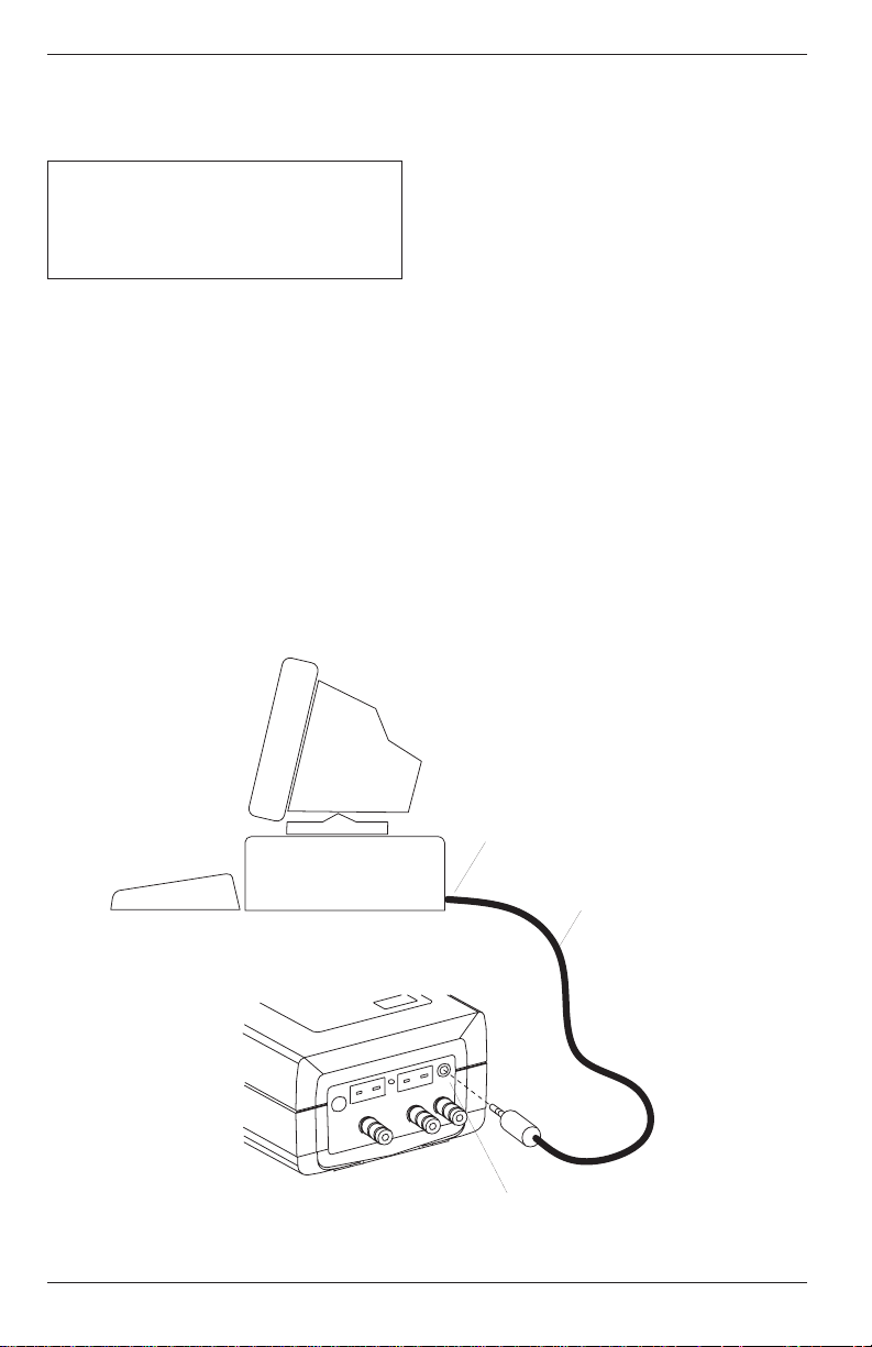
3.2.2 Using the Optional Power Supply
If an Optional Power Supply is to be used:
1. Connect the output plug of the Optional Power Supply to the
analyzer’s power supply jack (Figure 3-2).
2. Plug the Optional Power Supply into an appropriate AC wall outlet.
The analyzer will now operate and function normally.
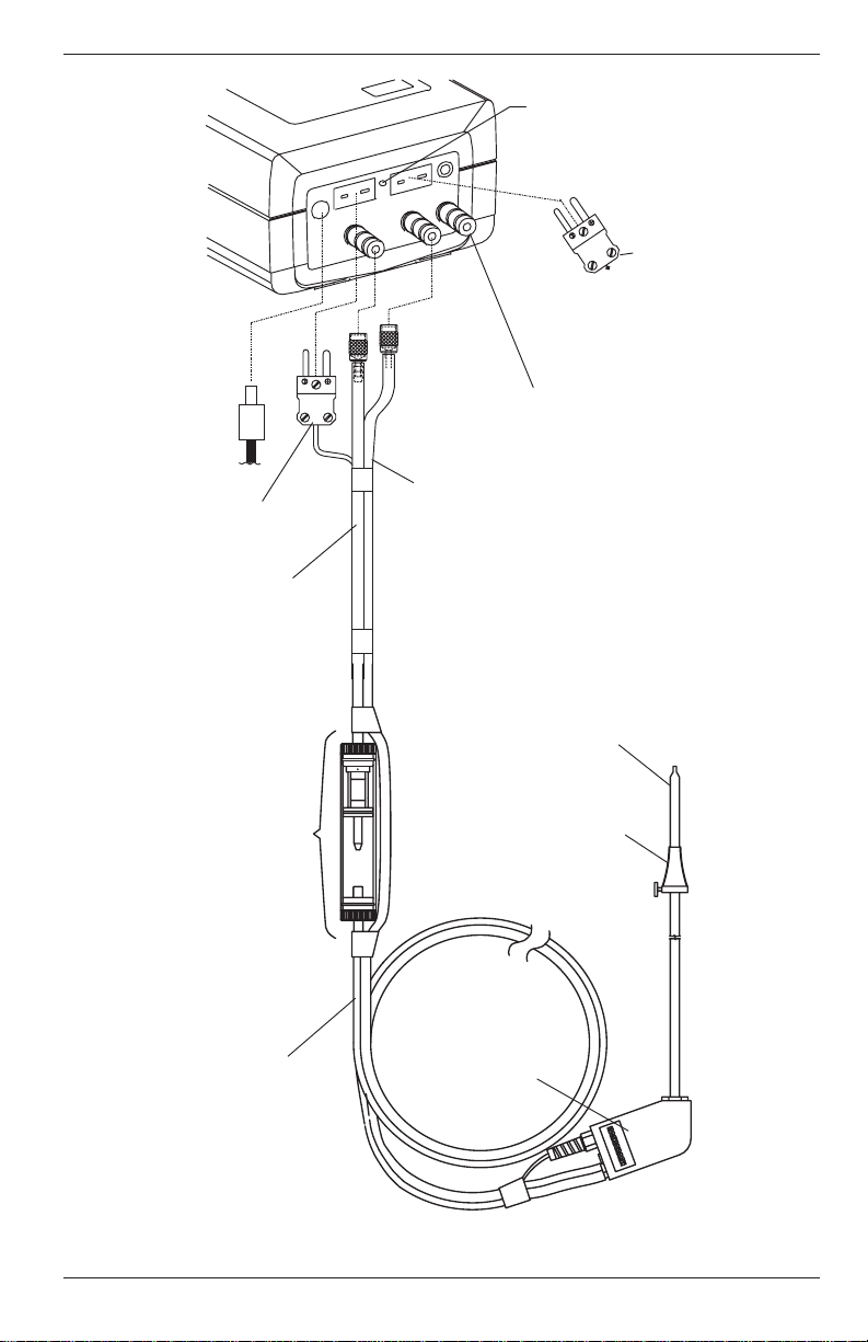
3.3 Connecting the Probe
To attach the probe to the analyzer (Figure 3-2):
1. Push the yellow-banded, quick-connect Flue Gas Hose (giving a slight
twist) onto the analyzer’s GAS sample-inlet fitting.
2. Push the blue-banded, quick-connect Draft Hose (giving a slight twist)
onto the analyzer’s DRAFT sample-inlet fitting.
3. Push the Flue Gas Thermocouple into the T-STACK jack (connector
fits in only one way).
NOTE: The PCA has a built in room-air thermocouple.
Perform Step 4 only if the Optional Room Air/Primary Air
Thermocouple is used.
4. Push the Optional Room Air/Primary Air Thermocouple into the
T-AIR jack (connector fits in only one way).
NOTE: In order for the PCA to correctly calculate combustion efficiency when the burner’s primary-air temperature is
not the same as room temperature, the primary-air temperature should be measured using the optional Primary Air
Thermocouple.
Inspect all the hoses for cracks. If any hose is defective, replace the entire
probe assembly. Check that the water trap is dry and the filter is not
dirty or saturated with water.
3-2
Instruction 24-9351
Page 15
PCA
POWER
Setup
Reset Button
T-AIR
RESET
T-STACK
GAS
Room Air /
Primary Air
Thermocouple
(Optional)
Power Supply
110V/60Hz
230V/50Hz
(Optional)
Flue Gas
Thermocouple
Water
Trap / Filter
Assembly
Pressure Reference
Port (Used in the
Measurement of
Differential Pressure)
Draft Hose
Flue Gas
Hose
Probe Tube
Adjustable
Probe Stop
Figure 3-2. Connecting the Probe to the Analyzer
Instruction 24-9351
Flue
Gas
Hose
Probe
Handle
3-3
Page 16

Setup
PCA
3.4 Configuring the PCA
The PCA is configured at the factory for the parameters shown below, but
can be changed by following the instructions in the associated sections.
Function Parameters To Change,
Refer to . . .
Fuel Natural Gas Section 4.8
Temperature ºC Section 4.13
Optional Draft MB Section 4.14
Language English Section 4.15
Display Mode* CO & NX Section 4.16
Time HR:MIN:SEC Section 4.17
Date** DD.MM.YY Section 4.17
Printer IrDA Section 4.18
* Available only on the PCA 30, 35, 60, & 65
** The year displays as two digits on the instrument, and
four digits on the printout.
3-4
Instruction 24-9351
Page 17
PCA
Operation
4.0 OPERATION
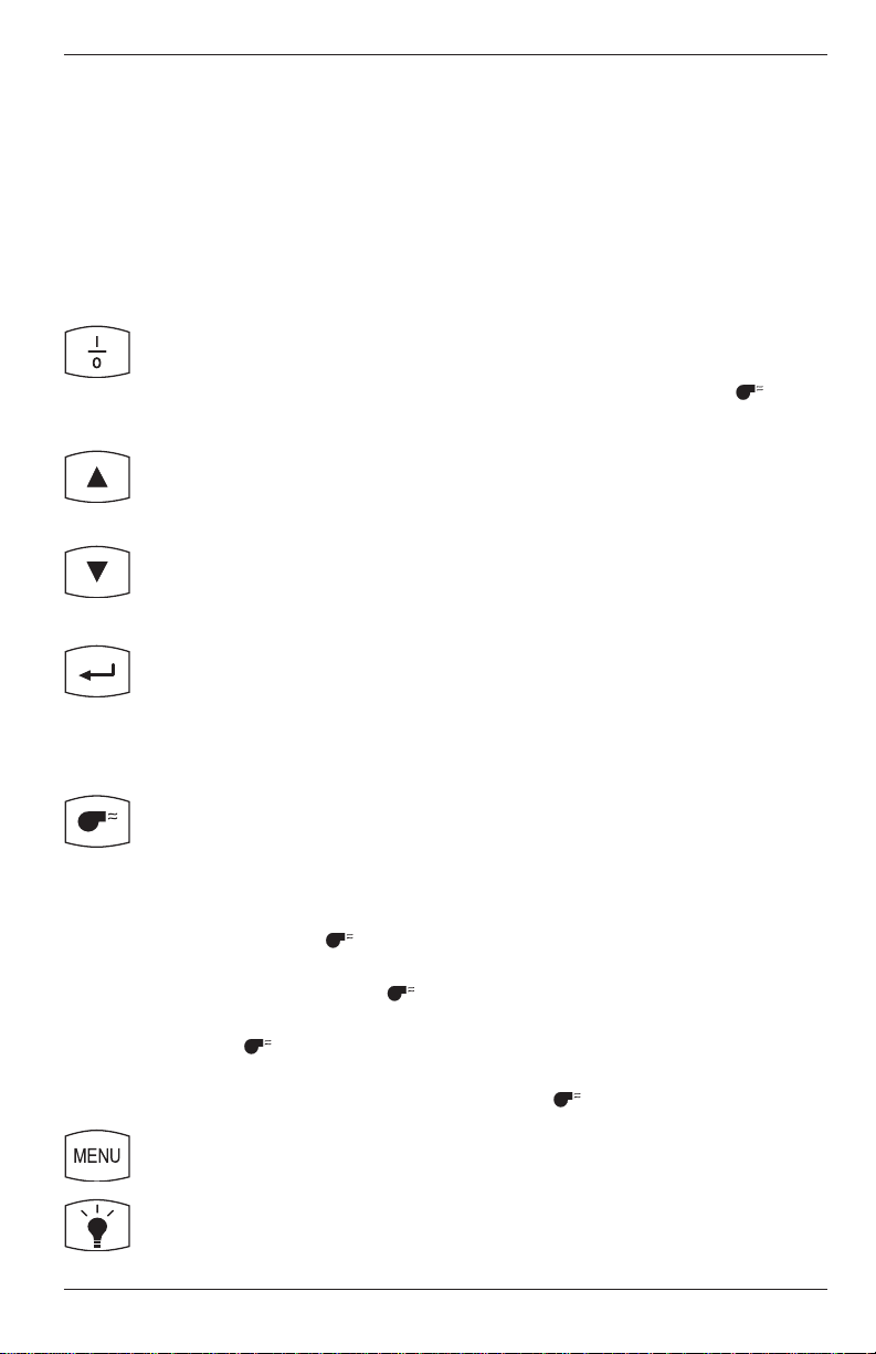
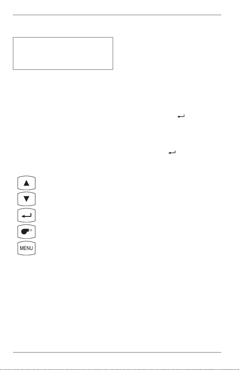
4.1 Key Pad Functions
Descriptions of the key pad functions are given below. Note that most of
the front panel key pad buttons perform multiple functions as determined
by what screen is being displayed at the time.
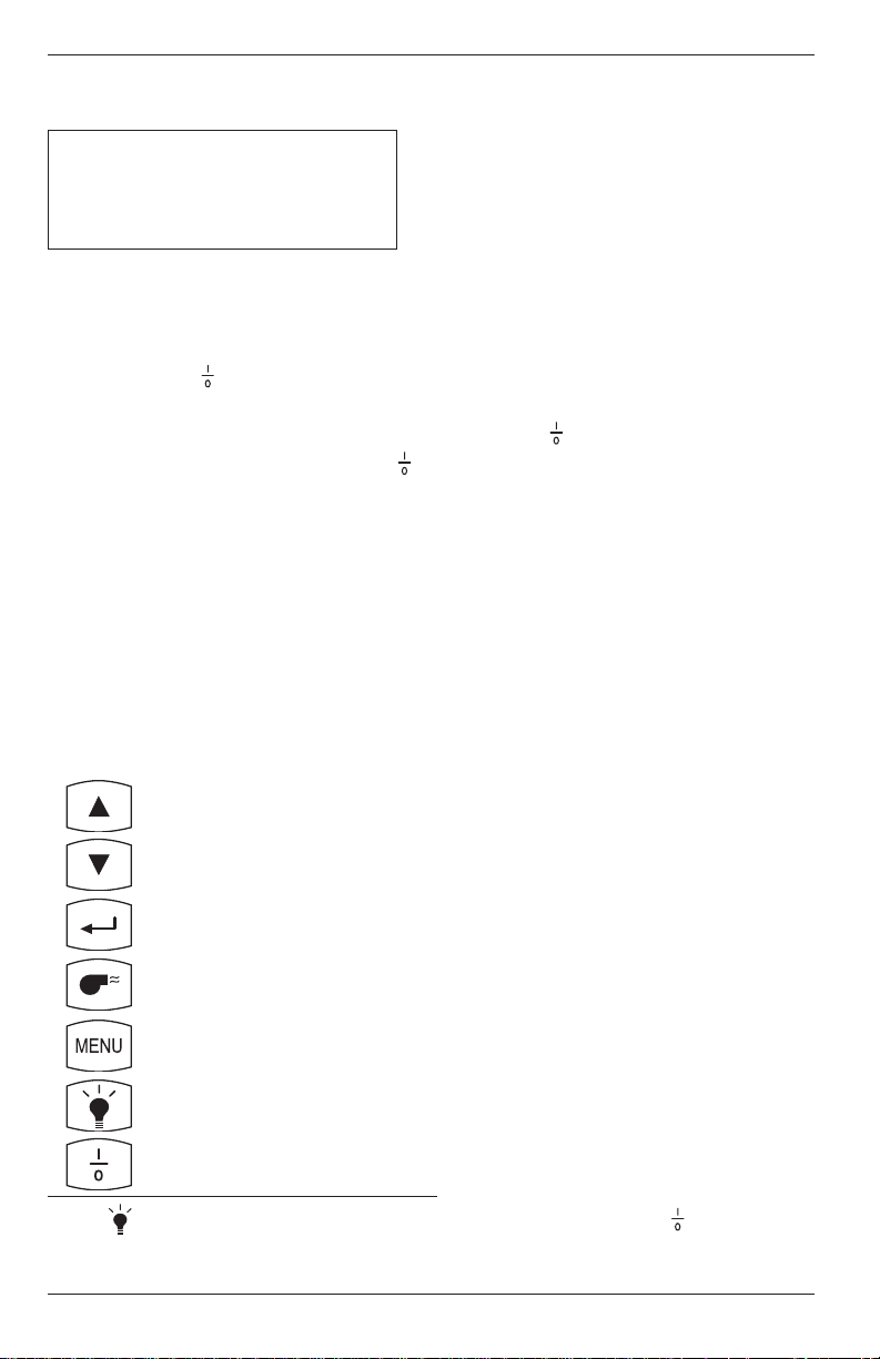
Turns the analyzer ON and OFF. Note that there is a 5 second
delay before the instrument actually turns OFF, thus allowing an
operator to turn the instrument back ON by pressing the key
to prevent the accidental loss of test data.
Moves the cursor [z] in front of a menu item up through the
displayed items. This key also increases alphanumeric values in
screens requiring a value change.
Moves the cursor [z] in front of a menu item down through the
displayed items. This key also decreases alphanumeric values in
screens requiring a value change.
Chooses the highlighted item (the item with the cursor [z] in front
of it) in all menus and screens. This key also causes the cursor to
enter the number field in the Maintenance Password Screen, and
causes the cursor to advance to the next field position in screens
requiring multiple alphanumeric entries.
Starts and stops a combustion test when the Combustion Test
Screen is displayed. Pressing this key in any other screen almost
always returns the instrument to the Combustion Test Screen.
However, there are four situations where this key behaves as an
enter key: 1) After entering a correct password in the Password
Screen, press the key to display the first calibration screen.
2) After entering an offset or span value in any of the Calibration
Edit Screens, press the key to store the new values. 3) After
entering a time or date value in the Time/Date Setup Screen,
press the key to store the new values and return the cursor to
the left side of the display. 4) After entering text in either the ID
Setup or User Name Screens, press the key to store the text.
Advances the display to the next menu screen.
Turns the backlight ON and OFF.
Instruction 24-9351
4-1
Page 18
Operation
PCA
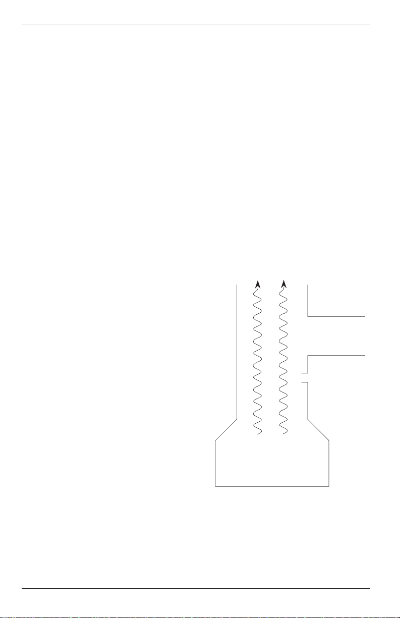
4.2 Sampling Hole Location
The analyzer requires that a 13 mm (½ in.) diameter sampling hole be
made in the furnace stack to accommodate the probe stop on the Probe
and Hose Assembly.
Locate the sampling hole downstream from the last heat exchanger,
and upstream from any source of dilution, such as a draft diverter
(Figure 4-1).
IMPORTANT! As the distance between the last heat exchanger and sampling point increases, stack loss will falsely
decrease due to heat loss by convection from the flue or stack.
For residential and light-commercial combustion-equipment applications,
the following recommendations are applicable:
• Oil Gun Burners – Locate sampling
hole at least 30 cm (12 in.) downstream from the furnace breaching,
and at least 15 cm (6 in.) upstream
from the furnace side of the draft
regulator.
• Gas Burners – Locate sampling hole
at least 15 cm (6 in.) upstream from
the furnace side of the draft diverter
on gas-converted units. For gasdesigned equipment, the probe may
be inserted down into the flue
through the draft diverter or hood.
FLUE GAS FLOW
(Downstream)
DRAFT
DIVERTER/
REGULATOR
SAMPLE
POINT
(Upstream)
FURNACE
BREECHING
Figure 4-1. Sampling Hole Location
4-2
Instruction 24-9351
Page 19

PCA
Operation
4.3 Combustion Test
IMPORTANT! Large rapid changes in the temperature of
the analyzer can affect its accuracy. This is important to
know if the analyzer is stored in a cold place (such as an
unheated vehicle in the winter) and then taken into a warm
furnace area. For the most accurate test results, allow the
analyzer to warm up to room temperature before use (about
10 minutes).
4.3.1 Analyzer Turn On and Warm Up
IMPORTANT! Be sure the probe is at room temperature
before performing the following steps.
1. Make sure that the analyzer is properly set up per Section 3.0.
2. Place probe in an area of fresh, ambient air; then press the analyzer’s
key.
3. Wait for the analyzer to countdown through its 60 second warmup
period; then perform one of the following:
• If no errors were detected during warmup, the Combustion
Test Screen will be displayed. Skip Step 4, and go to Section 4.3.2.
• If an error was detected during warmup, proceed with Step 4.
4. If one or more errors were detected by the microprocessor during
warmup, these errors will be displayed at the bottom of the Sensor
Status Screen. Address any problems now per Section 7.2; then repeat
this procedure starting with Step 1.
NOTE: If the error detected is not critical to your test, the
instrument can still perform any test not using the function
disabled by the error.
Instruction 24-9351
4-3
Page 20
Operation
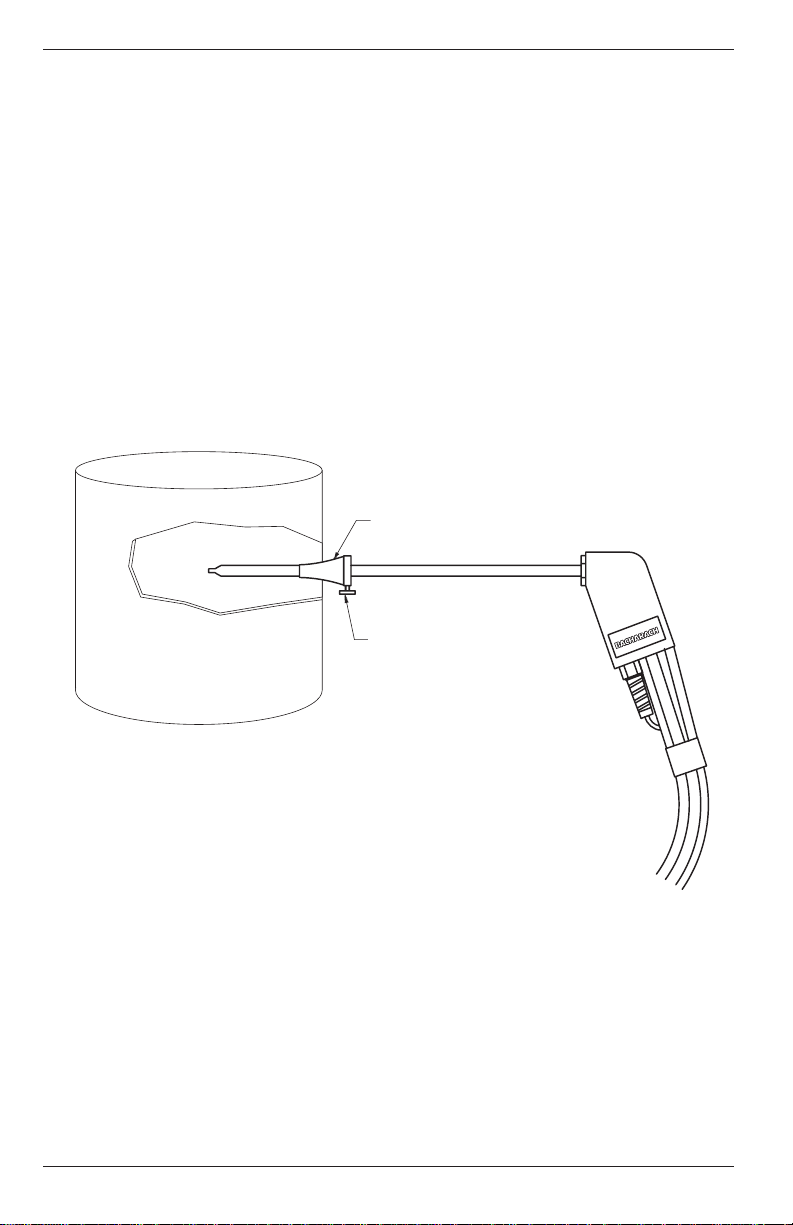
4.3.2 Installing Probe in the Stack
1. After making a sampling hole in the stack (Section 4.2), and turning
on the analyzer (Section 4.3.1), screw the probe stop supplied with the
Probe and Hose Assembly into the sampling hole (Figure 4-2).
2. Insert the probe through the hole in the probe stop, then position the
probe tip inside the stack, near its center. Tighten the thumbscrew on
the probe stop to secure the probe.
PROBE STOP
PCA
4-4
THUMBSCREW
Figure 4-2. Installing the Probe
Instruction 24-9351
Page 21

PCA
Operation
4.3.3 Performing a Combustion Test
IMPORTANT: If the burner’s primary-air temperature is
not the same as the room temperature, then be sure the
Optional Room Air / Primary Air Thermocouple is installed
per Section 3.3.
1. With the Combustion Test Screen displayed and the probe installed in
the stack, press the key to start a combustion test (refer to Section 4.7).
2. Once all sensor readings are indicated on the screen: A) Loosen the
thumbscrew on the probe stop. B) Move the probe in and out of the
stack until the stack’s core temperature (hot spot) is located.
C) Tighten the thumbscrew to prevent further movement of the probe.
Locating the highest stack temperature is very important for accurate
combustion calculations.
3. You can now begin burner-service procedures. The readings on the
analyzer change quickly to show changes in burner performance.
CAUTION
With the Water Trap / Filter Assembly stood up on its Outlet
End, do not let water condensate build up beyond the tip of
the riser tube. The sensors could be damaged if water would
enter the analyzer. Drain the water condensate after every
combustion test (refer to Section 6.4).
4. Pressing the key will save the Combustion Test Screen readings
while a test is in progress. Moving the cursor (z) in front of the print
( P) function using the s key, and then pressing will print the test
information to an optional printer.
4.3.4 Ending a Combustion Test
1. Press the key to end a combustion test.
WARNING!
Burn hazard! Allow a hot probe to cool for about 5 minutes
before handling.
Instruction 24-9351
4-5
Page 22

Operation
CAUTION:
Do not place a hot probe inside the instrument’s carrying case.
Allow the probe to cool before storage.
2. Loosen the thumbscrew on the probe stop; then remove the probe and
probe stop from the stack.
3. If data was saved during the combustion test, you can turn off the
analyzer and review or print the stored data at a later time as described in Sections 4.10 and 4.23.
4.3.5 Turning Off the Analyzer and Purging the CO Sensor
Turn off the analyzer by pressing the key.
If the key is pressed while the CO reading is 100 ppm or higher, the
pump will automatically turn on (if not already running) to purge the
analyzer of CO.
IMPORTANT! The analyzer’s probe must be removed from
the stack during the purging process to allow fresh air to be
drawn through the analyzer.
PCA
The following message is displayed while the analyzer is being purged.
PURGING CO SENSOR
As soon as the CO level falls below 100 ppm, the pump turns off and the
analyzer starts its normal 5 second turn-off sequence.
To abort the purging process and immediately start the analyzer’s turn-off
sequence, press the key.
NOTE: Turning the analyzer off initiates a 5-second delay,
during which time the unit can be turned on again without
any warmup time. You can turn the analyzer back on during
this 5-second delay by pressing the key.
4-6
Instruction 24-9351
Page 23
PCA
Operation
4.4 Differential Pressure Measurement
The difference in pressure (∆P) between two areas can be measured by
using the PCA’s two pressure ports and DRAFT Screen. By using Pressure Port 2 (–) as the reference, the pressure applied to Port 1 (+) will be
displayed on the DRAFT Screen as the differential pressure between the
two ports.
1. Turn on the analyzer by pressing the key; wait for the warmup cycle
to complete; then press the MENU key until the first DRAFT Screen is
displayed (refer to Section 4.9). If a TA-SENSOR ERROR is displayed
because the probe’s thermocouple is not plugged into the analyzer, then
press the key to acknowledge the error before pressing the MENU
key.
2. While the first DRAFT Screen is displayed, remove any hoses connected to Pressure Ports 1 and 2; then press the key to zero these
ports at atmospheric pressure.
3. Connect two sampling hoses to
Pressure Ports 1 and 2
(Figure 4-3). Then place the open
end of each hose into the areas
DRAFT
DRAFT – 2.25 MB
HOT SPOT ---- °C P
«S
being measured.
4. The differential pressure between the two areas is now displayed on
the third DRAFT Screen. If the pressure at Port 1 is higher than
Port 2, then the pressure difference will be positive. But if the pressure at Port #1 is lower, then the pressure difference will be negative.
The reading shown in this example indicates that the pressure at
Port 1 is 2.25 mb lower than the pressure at Port 2.
Sampling Hoses with quickconnect fittings are available
as an optional accessory.
Refer to Section 8.2.
Pressure Port 2(–)
Pressure Port 1(+)
Reference
Figure 4-3. Differential Pressure Hose Connections
Instruction 24-9351
4-7
Page 24
Operation
PCA
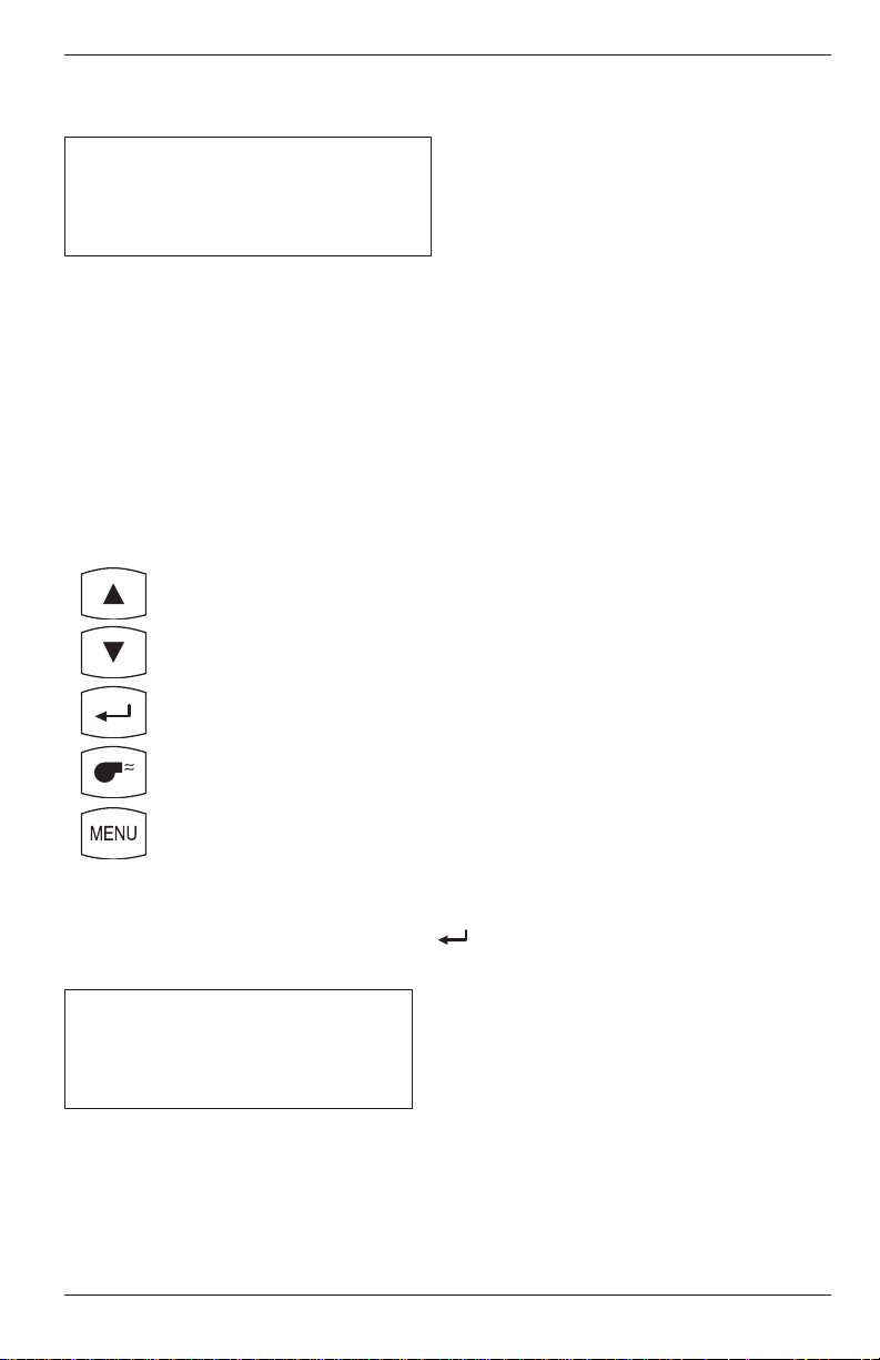
4.5 Warmup Screen
BACHARACH, INC.
PCA xx
WARMUP yy
Where: xx = Instrument Model Number
yy = Counts down from 60 seconds
As soon as the key is pressed, the instrument’s serial number and
software version number are displayed for approximately 3 seconds. To
continuously display these items, hold down the key at start-up. The
warmup cycle continues after the key is released.
The Warmup Screen is displayed during the analyzer’s 60 second warmup
cycle, during which time the “Warmup” value (yy) counts down to zero.
After the warmup cycle is complete (and if the unit is working correctly)
the instrument will flash NO ERRORS DETECTED and go directly to
the Combustion Test Screen (Section 4.7). If there is a problem, however,
with one or more of the sensors, the Sensor Status Screen (Section 4.6) is
displayed with error message(s) appearing at the bottom of the screen.
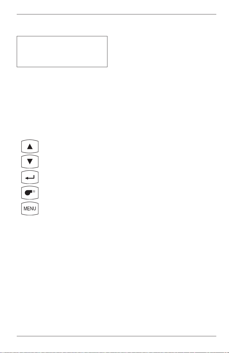
Front Panel Key Functions:
– No Action
– No Action
– No Action
– No Action
– No Action
– Toggle Backlight ON/OFF*
– Turn analyzer OFF*
* The button will always turn the backlight on and off, and the key will
always turn the analyzer on and off. These two keys will not be mentioned
in the remainder of this section.
4-8
Instruction 24-9351
Page 25
PCA
Operation
4.6 Sensor Status Screen
BACHARACH, INC.
PCA xx
WARMUP 0
z
Where: xx = Instrument Model Number
z = Sensor(s) in error
If there is problem with one or more of the sensors, the Sensor Status
Screen will be displayed after the analyzer has gone through its warmup
cycle (refer to Section 7.2 for a listing of the error codes).
Front Panel Key Functions:
– No Action
– No Action
– No Action
– Go to Combustion Test Screen
– No Action
Instruction 24-9351
4-9
Page 26

Operation
4.7 Combustion Test Screen
PCA models 10–25, 40–55 PCA models 30, 35, 60, & 65
O2 4.0 CO 12 HLD O2 4.0 CO 12 HLD
C2 9.5 CU 15 NG C2 9.5 NX 10 NG
TL 20.0 TA 190 P TL 20.0 TA 190 P
qA 8.1 LA 1.24
«S qA 8.1 LA 1.24 «S
PCA
This screen shows:
O2 ...............Oxygen content in flue gas (%)
C2 ...............Carbon Dioxide content
present in flue gas (%)
TL ...............Primary/Ambient air temp. (°F)
qA ...............Stack Loss
CO* .............Carbon Monoxide content in flue gas (ppm)
CU*............. Carbon Monoxide content referenced to 0% Oxygen (ppm)
TA ............... Stack (Flue gas) temperature (°F)
LA ............... LAMBDA
NX*.............Nitric Oxide content in flue gas (ppm)
NU* ............Nitric Oxide content referenced to 0% Oxygen (ppm)
HLD/RUN ..PCA on hold / PCA running test
NG .............. Fuel code for natural gas (see Section 4.8 for other codes)
P.................. Print Data
S..................Save Data
O2 4.0 CU 15 HLD
C2 9.5 NU 12 NG
TL 20.0 TA 190 P
qA 8.1 LA 1.24 «S
- OR -
* For PCA models 30, 35, 60 and 65, you have the option of displaying either
CO & NX, or CU & NU. Refer to Section 4.16 for setup instructions.
NOTE: Refer to Section 7.3 if stars (****) , dashes (----) , or
Xs (XXXX) appear in the display.
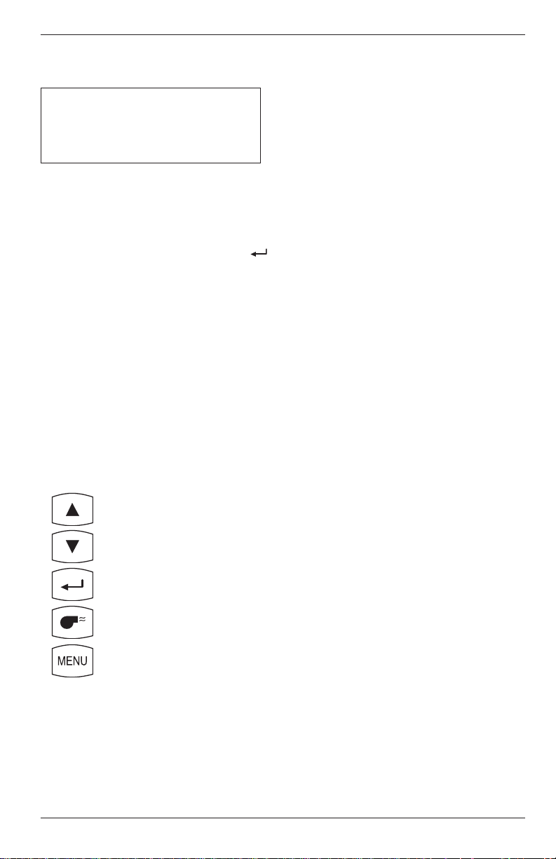
Front Panel Key Functions:
– Move cursor (z) up
4-10
– Move cursor (z) down
– Save or Print screen data
– Run test / Stop test
– Go to Fuel Selection Screen
Instruction 24-9351
Page 27
PCA
Operation
4.8 Fuel Selection Screen
«NATGAS FUEL
KOKS OIL NO.2
LEG OIL NO.6
LPG P-COAL
This screen is displayed by pressing the MENU key from the Combustion
Test Screen. This screen is used to select the fuel being burned.
To select a fuel, first use the st keys to move the cursor (z) in front of the
desired fuel, and then press the key.
NOTE: The fuel selected is saved as the default, and remains in memory after the PCA is turned off.
The fuel codes as displayed in the Combustion Test Screen:
NG = Natural Gas O#6 = Oil No. 6
KOK = Coal Gas PC = P-Coal (English, German, Dutch,
LPG = Propane French, Italian, Polish, and Spanish) or Biofuel
O#2 = Oil No. 2 (Danish, Finnish, and Swedish)
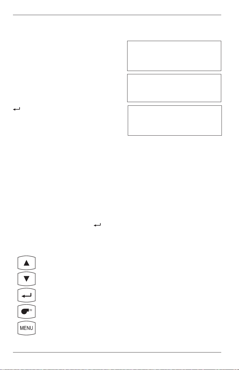
Front Panel Key Functions:
– Move cursor (z) up
– Move cursor (z) down
– Select Fuel
– Go to Combustion Test Screen
– Go to Draft Screens
Instruction 24-9351
4-11
Page 28
Operation
4.9 Draft Screens
PCA
The first Draft Screen is displayed by
repeatedly pressing the MENU key
from the Combustion Test Screen.
To measure draft, first zero the
analyzer’s pressure sensor to atmospheric pressure by disconnecting the
draft hose from the bottom of the
instrument, and then pressing the
key. Reconnect the draft hose after
the second Draft Screen appears
(shown for 3 seconds). The third
screen shows the current values of
draft and stack temperature as
measured by the analyzer.
When using the analyzer to make a
differential pressure measurement
(Section 4.4), the differential pressure
value will be displayed on the third
Draft Screen.
To save (S) or print (P) the screen
data, first use the st keys to move
the cursor (z) in front of the desired
function, and then press the key.
DRAFT
DISCONNECT DRAFT
HOSE
PRESS ±
DRAFT
RECONNECT DRAFT
HOSE
DRAFT
DRAFT – 0.25 XX
HOT SPOT 190 °C P
«S
Where: xx = Unit of measure.
Default is millibars (MB). See
Optional Draft SETUP Screen
(Section 4.14) for other choices.
Front Panel Key Functions:
– Move cursor (z) up
– Move cursor (z) down
– Save or Print screen data
– Go to Combustion Test Screen
– Go to Memory Directory Screen
4-12
Instruction 24-9351
Page 29

PCA
Operation
4.10 Memory Directory Screen
‘Standard’ PCA Screen ‘Advanced’ PCA Screen
MEMORY DIRECTORY MEMORY DIRECTORY
«M8 28.7.97 15:45 «98 28.7.97 15:45
M9 MEMORY EMPTY 99 MEMORY EMPTY
CLEAR MEMORY CLEAR MEMORY
The Memory Directory Screen is displayed by repeatedly pressing the
MENU key from the Combustion Test Screen. This screen is used to select
a memory location that contains saved data which an operator can review.
NOTE: A ‘standard’ PCA has 10 memory locations numbered M0 thru M9, while an ‘advanced’ PCA has 100 memory
locations numbered 0 thru 99.
To select a data-memory location, first use the st keys to move the
cursor (z) in front of the desired memory location; then press the key.
The saved data is now displayed in either the Combustion Test Screen or
Draft Screen, depending on whether the chosen memory location contains
combustion or draft information. To print the saved data, refer to Section 4.23.
After viewing or printing the saved data, use the st keys to move the
cursor (z) to the exit (E) function; then press . This will redisplay the
memory directory.
Selecting the CLEAR MEMORY function displays the Clear Memory
Screen from where all saved data can be erased (refer to Section 4.24).
Front Panel Key Functions:
– Move cursor (z) up
– Move cursor (z) down
– Display the data saved at the chosen memory location
– Go to Combustion Test Screen
– Go to Temperature Setup Screen, or the
Memory To PC Screen for Advanced units
Instruction 24-9351
4-13
Page 30
Operation
PCA
4.1 1 Memory to PC Screen
(For ‘Advanced’ PCA Models 40, 45, 50, 55, 60 & 65)
MEMORY TO PC
«TRANSMIT DATA
CLEAR MEMORY
The Memory To PC Screen is displayed by repeatedly pressing the MENU key
from the Combustion Test Screen. Use this screen to either transmit all
stored memory locations to a computer, or clear all memory locations.
TRANSMIT DATA
Before data can be transmitted to a personal computer, the PCA’s RS-232
output must first be connected to an unused COM port on the computer
using serial data cable Part No. 24-1073 (see Figure 4-4). Also, a communications program (i.e., ProcommPlus®, Windows 3.x Terminal, or Windows 9x Hyper Terminal) must be installed, and its communications
parameters configured for: 9600 baud, 8 data bits, 1 stop bit, no parity,
and no handshaking.
4-14
A t t a c h D B 9 C o n n e c t o r t o c o m p u t e r ' s
C O M 1 o r C O M 2 p o r t . I f n e c e s s a r y ,
u s e a 2 5 - p i n t o 9 - p i n a d a p t e r .
S e r i a l D a t a C a b l e
P a r t N o . 2 4 - 1 0 7 3
T - A I R
R E S E T
T - S T A C K
P O W E R
G A S
R S - 2 3 2 C o n n e c t o r
Figure 4-4. Connecting the Serial Data Cable
Instruction 24-9351
Page 31

PCA
Operation
Data is transmitted to a computer in ASCII comma-delimited format,
which can be captured as a text file and then opened in most commercially available spreadsheet programs. Note that each data record consists of 20 fields, some of which may be blank for different tests and PCA
models as listed in Tables 4-1 & 4-2.
Use the communication software to capture and save the received data as
an ASCII text file. Consult the software’s documentation for detailed
instructions on how to perform this procedure.
To start transmitting data, first use the st keys to position the cursor (z)
in front of TRANSMIT DATA and then press the key. Observe that
as PCA downloads its data, the word TRANSMITTING appears on the
display.
CLEAR MEMORY
To clear all memory locations, first use the st keys to position the cursor
(z) in front of CLEAR MEMORY and then press the key. The Clear
Memory Screen will then appear from where all saved data can be erased
(refer to Section 4.24).
Front Panel Key Functions:
– Toggle cursor (z) position
– Toggle cursor (z) position
– Select function next to cursor
– Go to Combustion Test Screen
– Go to ID Setup Screen
Instruction 24-9351
4-15
Page 32

Operation
TABLE 4-1. COMMA-DELIMITED FIELDS
Field Data Name or Value Label in Column
Headings
1 Instrument serial number SN
2 ID line 1 (up to 16 characters) ID1
3 ID line 2 (up to 16 characters) ID2
4 ID line 3 (up to 16 characters) ID3
5 Time of test (hh:mm:ss) TIME
6 Date of test (dd.mm.yyyy) DATE
1
7
8
9
10
11
12
13
14
15
16
17
18
1
1
1
1
1
1,2
1,2
1,3
1,3
1
1
Name of fuel (up to 16 characters) FUEL
Flue gas temperature TA
Air temperature TL
Temperature unit of measure (F or C) C/F
O
concentration in % O2
2
CO2 concentration in % C2
CO concentration in ppm CO
CO referenced to 0% O2 in ppm CU
NO concentration in ppm NX
NO referenced to 0% O2 in ppm NU
qA in % qA
Lambda LA
19 Draft measurement DR
20 Draft unit of measure MB/PA/WC
1
Empty data field for draft tests
2
Empty data field for PCA Models 40 and 45
3
Empty data field for PCA Models 40, 45, 50, and 55
PCA
TABLE 4-2. TYPICAL SPREADSHEET FOR A PCA 65
SN ID1 ID2 ID3 TIME DATE FUEL TA TL C/F O2
AX1020 ID LINE 1 ID LINE 2 ID LINE 3 9:03:27 19.01.1999 NATGAS 190 20 C 4
AX1020 ID LINE 1 ID LINE 2 ID LINE 3 9:10:35 19.01.1999
C2 CO CU NX NU qA LA DR MB/PA/WC
9.5 12 15 10 12 8.1 1.24 -0.25 MB
-0.25 MB
Line 1: Column Headings
Line 2: Typical Combustion Readings
Line 3: Typical Draft Reading
4-16
Instruction 24-9351
Page 33

PCA
Operation
4.12 ID Setup Screens
(For ‘Advanced’ PCA Models 40, 45, 50, 55, 60 & 65)
SETUP
«ID #1
ID #2
ID #3
This initial ID Setup Screen is displayed by repeatedly pressing the MENU
key from the Combustion Test Screen. Use this screen to edit three lines
of customer information (i.e., the customer’s name, location, and burner
reference number).
Each ID line can be up to 16 alphanumerical characters in length. All
three lines will appear at the top of each test record for the purpose of
identifying individual tests.
Front Panel Key Functions for the Initial ID SETUP Screen:
– Move cursor (z) upward
– Move cursor (z) downward
– Select ID Number that is next to the cursor for editing
– Go to Combustion Test Screen
– Go to Temperature Setup Screen
To enter a line of text, first use the st keys to position the cursor (z) in
front of the desired ID line; then press . The selected ID Line Number
Screen will then appear.
SETUP
ID #1
«
Now press the st keys until the desired letter or number is displayed.
Available characters include:
“(space)ABCDEFGHIJKLMNOPQRSTUVWXYZüäöß0123456789”
Instruction 24-9351
4-17
Page 34

Operation
PCA
Press to save the selected character and advance to the next position.
If you make a mistake, press until the cursor is over the incorrect
character and make your correction by again using the st keys. After all
the desired characters have been selected, press the key to save the
text line and return to the initial ID SETUP Screen.
NOTE: The entered ID information will be saved with all
future memory records until it is modified or deleted.
Front Panel Key Functions for the Individual ID SETUP Screens:
– Increment character
– Decrement character
– Select the displayed character and advance to the next
character position
– Save the text line and return to the initial ID SETUP Screen
– Abort any changes to the text line and return to the initial
ID SETUP Screen
4-18
Instruction 24-9351
Page 35

PCA
Operation
4.13 Temperature Setup Screen
SETUP
TEMPERATURE UNIT «°C
°F
The Temperature Setup Screen is displayed by repeatedly pressing the
MENU key from the Combustion Test Screen. Use this screen to setup the
analyzer to display temperature in either °C or °F.
To select the instrument’s temperature unit-of-measure, first use the st
keys to move the cursor (z) in front of °C or °F, and then press the
key.
Front Panel Key Functions:
– Move cursor (z) up
– Move cursor (z) down
– Select temperature unit of measure next to cursor
– Go to Combustion Test Screen
– Go to Draft Unit Setup Screen
Instruction 24-9351
4-19
Page 36

Operation
PCA
4.14 Draft Unit Setup Screen
SETUP
DRAFT UNIT «MB
PA
WC
The Draft Unit Setup Screen is displayed by repeatedly pressing the
MENU key from the Combustion Test Screen. Use this screen to setup the
analyzer to display draft in either millibars (MB), Pascals (PA), or inchesof-water column (WC).
To select the draft unit-of-measure, first use the st keys to move the
cursor (z) in front of MB, PA or WC, and then press the key.
Front Panel Key Functions:
– Move cursor (z) up
– Move cursor (z) down
4-20
– Select draft unit of measure
– Go to Combustion Test Screen
– Go to Language Setup Screen
Instruction 24-9351
Page 37

PCA
Operation
4.15 Language Setup Screen
SETUP SETUP
LANGUAGE DAN NED LANGUAGE DEU FRA
DEU SVE «ENG ITA
«ENG FIN ESP POL
The Language Setup Screen is displayed by repeatedly pressing the MENU
key from the Combustion Test Screen. Use this screen to select the
language displayed on the analyzer. The languages available for selection
include: Danish, German, English, Dutch, Swedish and Finnish; or
German, English, Spanish, French, Italian and Polish. The languages
displayed depend on the model of the analyzer (refer to Table 1-1).
To select a language, first use the st keys to move the cursor (z) in front
of the desired language, and then press the key.
Front Panel Key Functions:
– Move cursor (z) up
- OR -
– Move cursor (z) down
– Select Language
– Go to Combustion Test Screen
– Go to Display Mode Setup Screen
Instruction 24-9351
4-21
Page 38

Operation
PCA
4.16 Display Mode Setup Screen
(For PCA Models 30, 35, 60 & 65)
SETUP
DISPLAY «CO NX
CU NU
The Display Setup Screen is displayed by repeatedly pressing the MENU
key from the Combustion Test Screen. Use this screen to select whether
the Combustion Test Screen will display the measured values of Carbon
Monoxide and Nitric Oxide (CO and NX), or the calculated values of these
gases (CU and NU) referenced to 0% Oxygen.
To setup the display, first use the st keys to move the cursor (z) in front
of either CO NX (measured values), or CU NU (calculated values), and
then press the key.
Front Panel Key Functions:
– Move cursor (z) up
4-22
– Move cursor (z) down
– Select Display Mode
– Go to Combustion Test Screen
– Go to Time/Date Setup Screen
Instruction 24-9351
Page 39

PCA
Operation
4.17 Time/Date Setup Screen
SETUP
«TIME 15:45:06
DATE 31.10.01
The Time/Date Setup Screen is displayed by repeatedly pressing the
MENU key from the Combustion Test Screen. Use this screen to enter the
current time and date.
To enter the correct time or date, first use the st keys to move the
cursor (z) in front of the function you wish to change. Each position in the
TIME or DATE number fields can then be changed by first pressing the
key to move the cursor into the desired position, then pressing the st
keys to increase or decrease the value. Pressing moves the cursor to
the next position in the number field. Each individual position can be
edited in the same manner. Once the time or date values have been
entered, press to save the values and return the cursor to the left side
of the screen.
Front Panel Key Functions:
– Move cursor (z) up, or Increase value in number fields
– Move cursor (z) down, or Decrease value in number fields
– Select Time or Date to be changed, or move cursor (z) to next
position in the number field
– Go to the Combustion Test Screen, or save the time and date
values and return the cursor to the left side of the display
– Go to Printer Setup Screen
Instruction 24-9351
4-23
Page 40

Operation
PCA
4.18 Printer Setup Screen
SETUP
«IR - HP PRINTER
IR - IRDA
RS232
The Printer Setup Screen is displayed by repeatedly pressing the MENU
key from the Combustion Test Screen. Use this screen to choose the type
of connection and printer being used.
IR-HP: Infrared connection to a printer manufactured by Hewlett
Packard, which uses their proprietary infrared communications protocol
IR-IRDA: Infrared connection to a printer that uses a standard IrDA
protocol
RS232: Cable connection between the PCA and any serial printer
capable of 9600 baud operation
Use the st keys to move the cursor (z) in front of the desired connection
and printer, and then press the key to make the selection and return
to the Combustion Test Screen.
Front Panel Key Functions:
– Move cursor (z) up
– Move cursor (z) down
– Select connection and printer next to cursor
– Go to Combustion Test Screen
– Go to Maintenance Password Screen
4-24
Instruction 24-9351
Page 41

PCA
Operation
4.19 Maintenance Password Screen
MAINTENANCE
«PASSWORD XXX
Where: xxx = Password number
The Maintenance Password Screen is displayed by repeatedly pressing
the MENU key from the Combustion Test Screen. From here a three-digit
password must be entered to access the instrument’s Maintenance
Screens. The password number is provided on the Portable Combustion
Analyzer Calibration Password card that was supplied with the analyzer.
To enter the password, first press the key to move the cursor (z) into
the first number field, and then press the st keys until the first digit of
the password is displayed. Press to advance to the next number field
and enter the second digit. Perform the same sequence a third time to
complete the password. Press the key after the correct password is
entered to display the Maintenance Screen.
Front Panel Key Functions:
– No action, or increase value in password number field
– No action, or decrease value in password number field
– Move cursor (z) to next position in password number field
– Go to Combustion Test Screen (if cursor is on left side of
screen), or go to Maintenance Screen (if the proper password
was entered), or return cursor to left side of screen (if the
wrong password was entered)
– Go to Combustion Test Screen (if cursor is on left side of
screen), or return cursor to left side of screen (if cursor is in
the password number field)
Instruction 24-9351
4-25
Page 42
Operation
PCA
4.20 Maintenance Screen
MAINTENANCE
«CALIBRATION
USER NAME
The Maintenance Screen is displayed after entering the correct password
in the Maintenance Password Screen (Section 4.19). Use this screen to
enter either the analyzer’s Calibration Screen or User Name Screen.
To enter the Calibration Screen, first use the st keys to position the
cursor (z) in front of CALIBRATION, and then press the key.
NOTE: Section 5.0 contains detailed calibration procedures.
To enter the User Name Screen, first use the st keys to position the
cursor (z) in front of USER NAME, and then press the key.
Front Panel Key Functions:
– Toggle cursor (z) position
4-26
– Toggle cursor (z) position
– Select function next to cursor
– Go to Combustion Test Screen
– No action
Instruction 24-9351
Page 43
PCA
Operation
4.21 User Name Screens
USER NAME
«LINE 1
LINE 2
LINE 3
This initial User Name Screen is displayed after selecting USER NAME
from the Maintenance Screen (Section 4.20). Use this screen to either
enter or edit three lines of user-name information.
Each user-name line can be up to 20 alphanumerical characters in length.
All three lines will appear at the top of each printout for the purpose of
identifying the user or owner of the instrument (i.e., your company’s
name and address).
Front Panel Key Functions for Initial User Name Screen:
– Move cursor (z) upward
– Move cursor (z) downward
– Select Line Number that is next to the cursor for editing
– Go to Combustion Test Screen
– Return to Maintenance Screen
To enter text, first use the st keys to position the cursor (z) in front of
the desired line number; then press . The selected User Name Line
Number Screen will then appear.
USER NAME
LINE 1
«
Now press the st keys until the desired letter or number is displayed.
Available characters include:
“(space)ABCDEFGHIJKLMNOPQRSTUVWXYZüäöß0123456789”
Instruction 24-9351
4-27
Page 44

Operation
Press to save the selected character and advance to the next position.
If you make a mistake, press until the cursor is over the wrong character and make your correction by again using the st keys.
After all the desired characters have been selected, press to save the
text line and return to the initial User Name Screen.
Front Panel Key Functions for Individual User Name Screens:
– Increment character
– Decrement character
– Select the displayed character and advance to the next
character position
– Save the text line and return to the initial User Name Screen
– Abort any changes to the text line and return to the initial
User Name Screen
PCA
4.22 Saving Test Data
O2 4.0 CO 12 HLD DRAFT
C2 9.5 CU 15 NG DRAFT – 0.25 MB
TL 20.0 TA 190 P HOT SPOT 190 °C P
qA 8.1 LA 1.24 «S «S
To save the data displayed in either the Combustion Test or Draft
Screens, first use the st keys to move the cursor (z) in front of the save
(S) function and then press the key. The data will be saved in
memory, and can be recalled at any time from the Memory Directory
Screen (Section 4.10).
NOTE: Data will be automatically stored in the next free
memory location. After all memory locations are filled, any
additional data that is saved will start overwriting previously saved data starting at the first memory location.
4-28
Instruction 24-9351
Page 45

PCA
0
0 I
Operation
4.23 Printing Test Data
O2 4.0 CO 12 HLD DRAFT
C2 9.5 CU 15 NG DRAFT – 0.25 MB
TL 20.0 TA 190 «P HOT SPOT 190 °C «P
qA 8.1 LA 1.24 S S
Before printing, ensure that the correct
connection and printer has been selected per
Section 4.18.
The Print function is available in either the
Combustion Test Screen or the Draft Screen*.
NOTE: The data which is stored in
memory can also be printed. First go to
the Memory Directory Screen (Section
4.10) and display the data to be printed;
then print the data as described below.
When using an infrared printer:
1. Place analyzer in-line with the printer’s
IR input (see Figure 4-5).
6 0 °
m a x .
4 5 c m
( 1 8 i n . )
m a x .
2. Use the st keys to move the cursor (z) in
front of the print (P) function.
3. Press the key to start printing.
* The HOT SPOT line shown in the Draft
Screen does not appear on the printout.
Instruction 24-9351
M E N U
P C A
Figure 4-5. Aligning the Printer
4-29
Page 46

Operation
When using a serial printer:
1. First connect the analyzer to the printer using the optional RS-232
cable (see Figure 4-6).
2. Set the printer’s communication parameters to 9600 baud, 8 data bits,
1 stop bit, no parity, and no handshaking.
3. Use the st keys to move the cursor (z) in front of the print (P)
function.
4. Press the key to start printing.
A t t a c h D B 9 C o n n e c t o r t o p r i n t e r ' s
s e r i a l i n p u t p o r t . I f n e c e s s a r y ,
u s e a 2 5 - p i n t o 9 - p i n a d a p t e r .
PCA
4-30
S e r i a l D a t a C a b l e
P a r t N o . 2 4 - 1 0 7 3
T - A I R
R E S E T
T - S T A C K
P O W E R
G A S
R S - 2 3 2 C o n n e c t o r
Figure 4-6. Connecting a Serial Printer to the Analyzer
Instruction 24-9351
Page 47
PCA
Operation
4.24 Clear Memory Screen
CLEAR MEMORY
C
«E
The Clear Memory Screen is accessed from either the Memory Directory
Screen (Section 4.10) or the Memory to PC Screen (Section 4.11).
To clear all memory locations, use the st keys to place the cursor (z) in
front of the clear (C) function, and then press the key.
To return to the previous screen without clearing any memory locations, use
the st keys to place the cursor (z) in front of the exit (E) function; then
press .
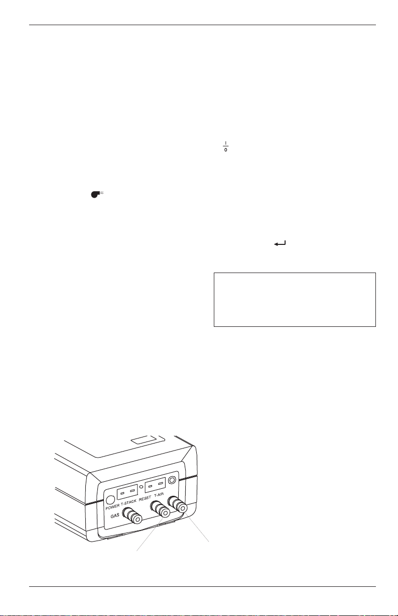
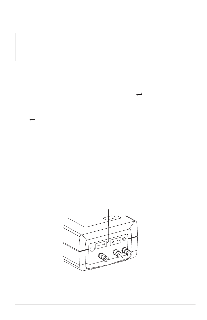
4.25 Resetting the Microprocessor
If the analyzer “locks-up” and cannot be turned OFF, reset the microprocessor by pressing the RESET button (Figure 4-7). The button can be
activated using the end of a paper clip.
Instruction 24-9351
RESET
BUTTON
T - A I R
R E S E T
T - S T A C K
P O W E R
G A S
Figure 4-7. Reset Button
4-31
Page 48

Operation
PCA
NOTES:
4-32
Instruction 24-9351
Page 49

PCA
Calibration
5.0 CALIBRATION
NOTE: Bacharach recommends that the PCA be calibrated
by your nearest Bacharach Service Center. Calibration,
however, can be performed in the field if your facility has the
necessary equipment and qualified personnel to perform the
procedures described in the sections that follow.
IMPORTANT! To prevent the loss of data during calibration, perform the following procedures with fresh batteries, or
using an optional Power Supply (see Section 3.2).
5.1 Sensor Check
IMPORTANT! Before turning on the analyzer or performing any of the calibration procedures, ensure that the analyzer will be sampling fresh air, and that the probe is at
room temperature.
When the analyzer is first turned on and allowed to cycle through its
60 second warmup period, and while sampling fresh air, the sensors are
checked (read) and calibrated (set) to the following ambient conditions:
• Oxygen sensor is spanned to 20.9%
• Carbon Monoxide sensor (if installed) is zeroed
• Nitric Oxide sensor (if installed) is zeroed
• Pressure sensor (if installed) is zeroed
Instruction 24-9351
5-1
Page 50

Calibration
PCA
5.2 Calibration Fixtures
A gas and a draft fixture will be required to perform the various calibration procedures described in this manual.
Material Required:
• Calibration Kit (Refer to Section 8.2)
• Calibration Gas Cylinder (Refer to Section 8.2)
• Bellows
• Micromanometer
Procedure:
Assemble the appropriate fixture, shown in Figure 5-1, as required by the
calibration procedure being performed.
GAS
FIXTURE
DRAFT
FIXTURE
Leave Top
Port Open
23 4 5
1
3
Parts Shown:
1. Gas Cylinder
2. Regulator*
3. Tubing*
4. Tee*
5. Flowmeter*
6. Fitting, Gas*
7. Fitting, Draft*
* Contained in Calibration Kit
M E N U
P C A
7
Micromanometer
3
3
M E N U
P C A
6
4
3
Bellows
5-2
Figure 5-1. Calibration Fixtures
Instruction 24-9351
Page 51

PCA
Calibration
5.3 Calibrate Menu Screen
«TA-ZERO CALIBRATE
TA-SPAN NX
TL-ZERO CO
TL-SPAN DRAFT
The Calibrate Menu Screen is displayed after entering the correct password in the Maintenance Password Screen (Section 4.19) and selecting
CALIBRATION from the Maintenance Screen (Section 4.20). Use this
screen to select the sensor to be calibrated.
Press the st keys until the cursor (z) is in front of the desired function,
and then press the key.
NOTE: TA is the stack temperature sensor, while TL is the
optional Room Air/Primary Air temperature sensor.
NOTE: If a sensor is not installed (i.e., the instrument does
not have a Nitric Oxide sensor or thermocouple simulator
installed), the corresponding calibration screen will not be
displayed.
Front Panel Key Functions:
– Move cursor (z) up
– Move cursor (z) down
– Select sensor to be calibrated
– Go to Combustion Test Screen
– Return to Maintenance Screen
Instruction 24-9351
5-3
Page 52

Calibration
5.4 Calibrate TA-Zero
Material Required:
• Thermocouple Simulator (K-type) Range: 0 to 300°C
Accuracy: ±0.3°C
Procedure:
1. With the analyzer turned off, first plug the simulator's K-type connector into the T-STACK jack (Figure 3-2); then turn on the analyzer and
wait for its warmup cycle to complete.
2. Enter the Calibration Menu Screen per Section 5.3; then choose
TA-ZERO to zero the analyzer’s stack temperature channel.
3. Adjust the simulator to 0° C (32° F).*
4. Wait until the MEASURED reading on the screen stabilizes. Then use
the st and keys to enter an APPLIED value that equals 0 °C
(32 °F).
PCA
Typical Calibrate TA-Zero Screen During Calibration Procedure:
CALIBRATE TA-ZERO
MEASURED 3.0°C
APPLIED 0000.0°C
4. Press the key to calibrate the analyzer’s MEASURED value to
that of the APPLIED value. At this time the Calibrate Menu Screen is
redisplayed.
* The calibration range for this screen is 0 – 5 °C (32 – 41°F). Any
attempt to calibrate outside this range will cause the analyzer to
display an error message.
5-4
Instruction 24-9351
Page 53

PCA
Calibration
5.5 Calibrate TA-Span
Material Required:
• Thermocouple Simulator (K-type) Range: 0 to 300°C
Accuracy: ±0.3°C
Procedure:
1. With the analyzer turned off, first plug the simulator's K-type connector into the T-STACK jack (Figure 3-2); then turn on the analyzer and
wait for its warmup cycle to complete.
2. Enter the Calibration Menu Screen per Section 5.3; then choose
TA-SPAN to span the analyzer’s stack temperature channel.
3. Set the simulator to 300° C (572° F).*
4. Wait until the MEASURED reading on the screen stabilizes. Then use
the st and keys to enter an APPLIED value that equals 300 °C
(572 °F).
Typical Calibrate TA-Span Screen During Calibration Procedure:
CALIBRATE TA-SPAN
MEASURED 295.0°C
APPLIED 0300.0°C
4. Press the key to calibrate the analyzer’s MEASURED value to
that of the APPLIED value. At this time the Calibrate Menu Screen is
redisplayed.
* The calibration range for this screen is 270 – 330 °C (518 – 626 °F).
Any attempt to calibrate outside this range will cause the analyzer to
display an error message.
Instruction 24-9351
5-5
Page 54

Calibration
5.6 Calibrate TL-Zero
Material Required:
• Thermocouple Simulator (K-type) Range: 0 to 300°C
Accuracy: ±0.3°C
Procedure:
1. With the analyzer turned off, first plug the simulator’s K-type connector into the T-AIR jack (Figure 3-2); then turn on the analyzer and
wait for its warmup cycle to complete.
2. Enter the Calibration Menu Screen per Section 5.3; then choose
TL-ZERO to zero the analyzer’s room-air/primary-air temperature
channel.
3. Set the simulator to 0 °C (32 °F).*
4. Wait until the MEASURED reading on the screen stabilizes. Then use
the st and keys to enter an APPLIED value that equals 0 °C
(32 °F).
PCA
Typical Calibrate TL-Zero Screen During Calibration Procedure:
CALIBRATE TL-ZERO
MEASURED 3.0°C
APPLIED 0000.0°C
4. Press the key to calibrate the analyzer’s MEASURED value to
that of the APPLIED value. At this time the Calibrate Menu Screen is
redisplayed.
* The calibration range for this screen is 0 – 5 °C (32 – 41 °F). Any
attempt to calibrate outside this range will cause the analyzer to
display an error message.
5-6
Instruction 24-9351
Page 55

PCA
Calibration
5.7 Calibrate TL-Span
Material Required:
• Thermocouple Simulator (K-type) Range: 0 to 300°C
Accuracy: ±0.3°C
Procedure:
1. With the analyzer turned off, first plug the simulator’s K-type connector into the T-AIR jack (Figure 3-2); then turn on the analyzer and
wait for its warmup cycle to complete.
2. Enter the Calibration Menu Screen per Section 5.3; then choose
TL-SPAN to span the analyzer’s room-air/primary-air temperature
channel.
3. Set the simulator to 100 °C (212 °F).*
4. Wait until the MEASURED reading on the screen stabilizes. Then use
the st and keys to enter an APPLIED value that equals 100 °C
(212 °F).
Typical Calibrate TL-Span Screen During Calibration Procedure:
CALIBRATE TL-SPAN
MEASURED 102.0°C
APPLIED 0100.0°C
4. Press the key to calibrate the analyzer’s MEASURED value to
that of the APPLIED value. At this time the Calibrate Menu Screen is
redisplayed.
* The calibration range for this screen is 90 – 110 °C (194 – 230 °F).
Any attempt to calibrate outside this range will cause the analyzer to
display an error message.
Instruction 24-9351
5-7
Page 56

Calibration
PCA
5.8 Calibrate NX
(For PCA Models 30, 35, 60 & 65)
The Nitric Oxide sensor needs to be spanned at regular intervals to
determine that it still meets its accuracy specification. Because of the
toxicity of Nitric Oxide gas, however, unless your facility has the necessary gas cylinders and personnel trained in the handling of toxic gases,
we recommend that the Nitric Oxide sensor be spanned by an authorized
Bacharach Service Center.
Material Required:
• Calibration Gas Fixture (Section 5.2)
• Gas Cylinder, 50 to 150 ppm Nitric Oxide with an analytical accuracy of
±1% (customer supplied)
Procedure:
1. Enter the Calibrate Menu Screen per Section 5.3. Then choose to
calibrate the NX sensor.
2. At the conclusion of Step 1 the pump should start running.
3. Using the Gas Fixture shown in Figure 5-1, attach the Nitric Oxide
calibration-gas cylinder to the analyzer’s GAS inlet.
4. Adjust the regulator of the calibration fixture for a flowmeter indication of approximately 2 SCFH.
5. Wait until the MEASURED reading on the screen stabilizes (approximately 3 minutes). Then use the st and keys to enter an
APPLIED value* that equals the concentration that is stamped on the
NX calibration-gas cylinder.
Typical Calibrate NX Screen During Calibration,
Using 100 ppm Nitric Oxide Calibration Gas:
CALIBRATE NX
MEASURED 092 PPM
APPLIED 0100 PPM
6. Press the key to calibrate the analyzer’s MEASURED value to
that of the APPLIED value. At this time the Calibrate Menu Screen is
redisplayed.
* The calibration range for this screen is 50 – 150 ppm. Any attempt to
calibrate outside range will cause the analyzer to display an error
message.
5-8
Instruction 24-9351
Page 57

PCA
Calibration
5.9 Calibrate CO
(For PCA Models 20, 25, 30, 35, 50, 55, 60 & 65)
Material Required:
• Calibration Gas Fixture (Section 5.2)
• Gas Cylinder, 500 ppm CO in air (Refer to Section 8.2)
• Gas Cylinder, CO (1000 ppm) and H2 (1000 ppm) in Nitrogen
(Refer to Section 8.2)
Procedure:
1. Enter the Calibrate Menu Screen per Section 5.3. Then choose to
calibrate the CO sensor.
2. At the conclusion of Step 1 the pump should start running.
3. Using the Gas Fixture shown in Figure 5-1, attach the CO calibrationgas cylinder to the analyzer’s GAS inlet.
4. Adjust the regulator of the calibration fixture for a flowmeter indication of approximately 2 SCFH.
5. Wait until the MEASURED reading on the screen stabilizes (approximately 3 minutes). Then use the st and keys to enter an
APPLIED value* that equals the concentration which is stamped on
the CO calibration-gas cylinder.
Typical CALIBRATE CO Screen During Calibration Procedure,
Using 500 ppm CO Calibration Gas:
CALIBRATE CO
MEASURED 492 PPM
APPLIED 0500 PPM
6. Press the key to calibrate the analyzer’s MEASURED value to
that of the APPLIED value. At this time the Test Gas CO/H2 Screen
is displayed.
* The calibration range for this screen is 250 – 1500 ppm. Any attempt
to calibrate outside this range will cause the analyzer to display an
error message.
Instruction 24-9351
5-9
Page 58

Calibration
PCA
7. Turn off the flow of CO calibration-gas; then remove the calibrationgas cylinder from the calibration fixture.
8. Attach a CO/H2 calibration-gas cylinder to the calibration fixture;
then adjust the regulator of the calibration fixture for a flowmeter
reading of approximately 2 SCFH.
9. Use the st and keys to enter a CO-VALUE that is the same as
the CO concentration which is stamped on the CO/H2 calibration-gas
cylinder.
Typical Test Gas CO/H2 Screen During Calibration Procedure:
TEST GAS CO/H2
-------------------
CO-VALUE XXXX
ENTER CO-VALUE
10. Press the key to save the CO-VALUE and display the Calibrate H2
Screen.
11. After calibration gas has been applied for approximately 3 minutes (to
allow for stabilization), use the st and keys to enter an APPLIED
value* that equals the H2 concentration stamped on the CO/H
2
calibration-gas cylinder.
Typical CALIBRATE H2 Screen During Calibration Procedure:
CALIBRATE H2
MEASURED 1050 PPM
APPLIED 1000 PPM
12. Press the key to calibrate the analyzer’s MEASURED value to
that of the APPLIED value. At this time the Calibrate Menu Screen is
redisplayed.
* The calibration range for this screen is 500–1500 ppm, any attempt to
calibrate outside this range will cause the unit to display an error
message.
5-10
Instruction 24-9351
Page 59

PCA
Calibration
5.10 Calibrate Draft
(For PCA Models 15, 25, 35, 45, 55 & 65)
Material Required:
• Calibration Fixture (Section 5-2)
• Bellows (adjustable)
• Micromanometer Range: ±20 mb (±8 in. H2O column)
Accuracy: ±0.025 mb (±0.01 in. H2O column)
Procedure:
IMPORTANT! In Step 1, do not connect the draft calibra-
tion fixture to the analyzer until the Calibrate Draft Screen
has been selected and displayed.
1. Enter the Calibrate Menu Screen per Section 5.3. Then choose to
calibrate the draft sensor.
2. With the Calibrate Draft Screen displayed, connect the hose from the
calibration fixture to the analyzer’s DRAFT port; then adjust the
bellows for a micromanometer reading of –10 mb (–4" H2O column).
3. Wait until the MEASURED reading on the screen stabilizes. Then use
the st and keys to enter an APPLIED reading* which equals the
Micromanometer reading.
Typical CALIBRATE DRAFT Screen During Calibration Procedure:
CALIBRATE DRAFT
MEASURED - 9.00 MB
APPLIED -10.00 MB
4. Press the key to calibrate the analyzer’s MEASURED value to
that of the APPLIED value. At this time the Calibrate Menu Screen is
redisplayed.
5. When all desired calibrations have been completed, press to exit to
the Combustion Test Screen.
* The calibration range for this screen is –5 to –15 mb, any attempt to
calibrate outside this range will cause the unit to display an error
message.
Instruction 24-9351
5-11
Page 60

Calibration
PCA
NOTES:
5-12
Instruction 24-9351
Page 61

PCA
Maintenance
6.0 MAINTENANCE
6.1 Routine Maintenance
Routine maintenance of the analyzer consists of: replacing the batteries,
cleaning the probe, draining the water trap, replacing the water trap
filter, and performing periodic calibration checks to ensure that the
analyzer is providing accurate readings.
• Replace the Batteries per Section 3.2.
• Clean the Probe per Section 6.3.
• Maintain the Water Trap/Filter Assembly per Section 6.4.
• Replace the Particulate Filter per Section 6.5
• Calibrate the analyzer per Section 5.0.
Instruction 24-9351
6-1
Page 62

Maintenance
PCA
6.2 Disassembly
Perform the following when a maintenance procedure calls for removing
the case, printed circuit board, pump, or sensors:
1. Remove the batteries (Section 3.2.1)
2. Place the analyzer face down on a work surface, then remove the
unit’s four rear-case screws.
3. Carefully lift the rear case from the analyzer, unplug the battery
compartment wires, then place the rear housing on a work surface
(see Figures 6-1 & 6-2).
B A T T E R Y
W I R E S
6-2
Figure 6-1. Disassembling the Analyzer
Instruction 24-9351
Page 63
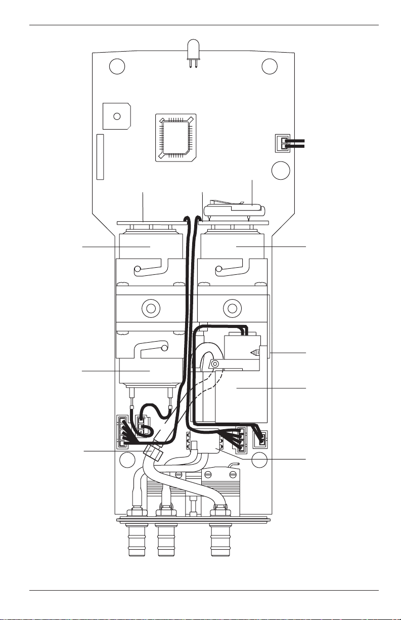
PCA
4
CO PCB
NX PCB
BIAS
BATTERY
Maintenance
TO
BATTERY
COMPARTMENT
FUSE
OPTIONAL
CARBON
MONOXIDE
SENSOR
OXYGEN
SENSOR
PARTICULATE
FILTER
RED
+–
BLACK
OPTIONAL
NITRIC
OXIDE
SENSOR
PUMP
MTG.
SCREWS
PUMP
DRAFT
SENSOR
Figure 6-2. Rear View of the PCB and Sensors
Instruction 24-9351
6-3
Page 64

Maintenance
PCA
6.3 Cleaning the Probe
The Probe Tube and the Probe Body will become dirty under normal use
(the water trap’s filter element should prevent soot from reaching the
analyzer’s internal components). If the probe assembly is not kept clean,
it could become clogged and restrict the flow of gas to the analyzer,
resulting in incorrect readings and calculations.
NOTE: An analyzer that is used to sample natural-gas
furnaces normally requires less frequent cleaning than an
analyzer used to sample oil or coal fired furnaces.
Equipment Required:
• Alcohol
• Aerosol can of Automotive Carburetor Cleaner
• Clean Rag
• Source of Compressed Air (optional)
Procedure:
1. Remove the rubber tubing from the barbed fitting(s) on the probe
handle (Figure 3-2).
CAUTION:
Carburetor cleaner attacks plastic components. Take precautions not to spray cleaner onto the probe handle or analyzer.
2. Insert the plastic-spray tube of the carburetor cleaner into the barbed
fitting(s) of the probe handle; then liberally spray carburetor cleaner
through the probe.
3. After spraying, remove all the residual cleaner by repeatedly flushing
the probe with alcohol.
4. Wipe off the surfaces of the probe and tubing with a clean rag.
5. Allow the parts to dry completely. If available, blow compressed air
through the probe to expedite the drying process.
6. Reassemble the parts of the probe assembly.
6-4
Instruction 24-9351
Page 65

PCA
Maintenance
6.4 Water Trap/Filter Assembly Maintenance
The Water Trap / Filter Assembly removes water condensate from the gas
sample, and also prevents soot from contaminating the internal components of the analyzer.
Drain the water condensate after every use.
Procedure:
1. Pull off the end-cap from the Inlet End of the Water Trap / Filter
Assembly (Figure 6-3).
2. Pour out all of the water condensate, and replace the end-cap.
Replace the filter element when it becomes
excessively dirty.
Equipment Required:
• Filter Element (Refer to Section 8.0)
Procedure:
1. Pull off the end-cap from the Outlet End of the Water Trap / Filter
Assembly (Figure 6-3).
2. Remove and discard the old filter element.
3. Install a new filter element and replace the end-cap.
F i l t e r E l e m e n t
O u t l e t
E n d
Figure 6-3. Water Trap/Filter Assembly
Instruction 24-9351
R i s e r T u b e
I n l e t
E n d
6-5
Page 66

Maintenance
PCA
6.5 Replacing the Particulate Filter
The internal particulate filter (Figure 6-2) prevents small dust and dirt
particles from entering and damaging the pump. Depending on your
environmental conditions, it is recommended to change the particulate
filter and fitting approximately every six months, or sooner if it becomes
blocked.
Equipment Required:
• Particulate Filter and Fitting (Refer to Section 8.0)
Procedure:
1. Remove the analyzer’s rear case and lay it aside (refer to Section 6.2).
2. Carefully pull off the tubing from the filter and fitting. Note the
orientation of tubing and fitting before removing.
3. Remove and discard the old filter and fitting and replace with new
ones. Be careful not to not pinch the tubing during reassembly.
4. Reassemble the analyzer in the reverse order of disassembly.
Instruction 24-93516-6
Page 67

PCA
Maintenance
6.6 Replacing the Oxygen Sensor
Replace the Oxygen Sensor when it has expired (when the analyzer’s
automatic O2 calibration fails and the unit displays the message “O2Sensor Error”).
NOTE: A "O2-SENSOR ERROR" displayed in the Sensor
Status Screen does not necessarily mean that the sensor has
expired. Before replacing the sensor, refer to Section 7.2 for
other possible causes of the error.
Equipment Required:
• Small Flat Blade Screw Driver
• Oxygen Sensor (Refer to Section 8.0)
Procedure:
1. Remove the analyzer’s rear case and lay it aside (refer to Section 6.2).
2. Remove the Oxygen Sensor connector from the printed circuit board;
then carefully pull off the two wires connected to the pins of the
sensor (see Figure 6-2).
3. Push in and turn the sensor counterclockwise (watching the notch on
top) until it stops; then pull the sensor out of its housing.
4. To install a new sensor, push the sensor into the housing and turn it
clockwise until it locks in place.
5. Connect the black (–) and red (+) wires, which were removed from the
old sensor in Step 2, to the pins of the new sensor. Be sure to observe
polarity as marked on the sensor.
6. Reinstall the sensor connector onto the printed circuit board.
7. Reassemble the analyzer. Then allow the sensor to be connected in
the circuit for at least 1 hour before continuing.
8. Place the analyzer in an area of fresh air and turn it ON. After the
warmup cycle, observe that the Sensor Status Screen should not show
an O2 sensor error.
Instruction 24-9351
6-7
Page 68

Maintenance
6.7 Replacing the Nitric Oxide Sensor
(For PCA Models 30, 35, 60 & 65)
Replace the Nitric Oxide sensor when it has expired (can no longer be
calibrated).
NOTE: A "NX-SENSOR ERROR" displayed in the Sensor
Status Screen does not necessarily mean that the sensor has
expired. Before replacing the sensor, refer to Section 7.2 for
other possible causes of the error.
Equipment Required:
• Small Flat Blade Screw Driver
• Nitric Oxide Sensor (Refer to Section 8.0)
• Nitric Oxide Sensor Filter (Refer to Section 8.0)
Procedure:
1. Remove the analyzer’s rear case and lay it aside (refer to Section 6.2).
2. Carefully pull the printed circuit board off the rear of the Nitric Oxide
sensor (see Figure 6-2).
3. Push in and turn the sensor counterclockwise (watching the notch on
top) until it stops; then pull the sensor out of its housing.
4. Install a new sensor by first pushing it into its housing, and then
turning it clockwise until it locks in place.
PCA
5. Install the circuit board, which was removed in Step 2, onto the rear
of the sensor.
6. Reassemble the analyzer and allow the sensor to be connected in the
circuit for at least 4 hours before continuing.
7. Place the analyzer in an area of fresh air and turn it ON.
8. Calibrate the analyzer per Section 5.0.
6.7.1 Replacing the Nitric Oxide Sensor Filter
Replacing the orange filter on the Nitric Oxide sensor once a year could
increase the life of the sensor.
Procedure:
1. Remove the Nitric Oxide sensor per Section 6.7.
2. Pry the orange filter from the Nitric Oxide sensor and replace it with
a new one.
3. Reinstall the sensor.
6-8
Instruction 24-9351
Page 69

PCA
Maintenance
6.7.2 Replacing the Nitric Oxide Sensor Bias Battery
A single lithium battery, located on the Nitric Oxide printed circuit board
(see Figure 6-2), applies a constant bias voltage to the Nitric Oxide sensor
even while the instrument is turned off. This battery has a life expectancy
of at least 2 years.
Replace the Nitric Oxide bias battery toward the end of its expected life.
Equipment Required:
• Bias Battery (See Section 8.0)
Procedure:
1. Remove the analyzer’s rear case and lay it aside (refer to Section 6.2).
2. Remove old battery from its holder (see Figure 6-2).
3. Insert the new battery (positive side facing upwards) into its holder.
4. Reassemble the analyzer.
5. Before powering up and using the instrument, allow the Nitric Oxide
sensor to stabilize as described below. Recalibration of the Nitric
Oxide sensor is usually not required.
Depending on how long the Nitric Oxide sensor was without bias
voltage, the time required for the sensor to completely stabilize varies
from less than a minute to several days. Typical stabilization times
are shown below. Generally, however, the sensor is sufficiently stable
after 4 hours for measurement purposes.
Bias removed for. . Stabilization time
Less than 15 min. Less than 1 min.
Less than 1 hr. Less than 5 min.
Less than 2 days Less than 4 hr.
Greater than 2 days Up to 2 days
Instruction 24-9351
6-9
Page 70

Maintenance
PCA
6.8 Replacing the Carbon Monoxide Sensor
(For PCA Models 20, 25, 30, 35, 50, 55, 60 & 65)
Replace the Carbon Monoxide sensor when it has expired (can no longer
be calibrated).
NOTE: A "CO-SENSOR ERROR" displayed in the Sensor
Status Screen does not necessarily mean that the sensor has
expired. Before replacing the sensor, refer to Section 7.2 for
other possible causes of the error.
Equipment Required:
• Small Flat Blade Screw Driver
• Carbon Monoxide Sensor (Refer to Section 8.0
• Carbon Monoxide Sensor Filter (Refer to Section 8.0)
Procedure:
1. Remove the analyzer’s rear case and lay it aside (refer to Section 6.2).
2. Carefully pull the printed circuit board off the rear of the Carbon
Monoxide sensor (see Figure 6-2).
3. Push in and turn the sensor counterclockwise (watching the notch on
top) until it stops; then pull the sensor out of its housing.
4. Remove the wire jumper from the pins of the new sensor.
5. Install the new sensor by first pushing the sensor into its housing,
and then turning clockwise until it locks in place.
6. Install the circuit board, which was removed in Step 2, onto the rear
of the sensor.
7. Reassemble the analyzer; then allow the sensor to be connected in the
circuit for at least 1 hour before continuing.
8. Place the analyzer in an area of fresh air and turn it ON.
9. Calibrate the analyzer per Section 5.0.
6-10
Instruction 24-9351
Page 71

PCA
Maintenance
6.8.1 Replacing the Carbon Monoxide Sensor Filter
Replacing the red filter on the Carbon Monoxide sensor once a year could
increase the life of the sensor.
Procedure:
1. Remove the Carbon Monoxide sensor per Section 6.8.
2. Pry the red filter from the Carbon Monoxide sensor and replace it with a
new one.
3. Reinstall the sensor.
Instruction 24-9351
6-11
Page 72

Maintenance
PCA
6.9 Replacing the Pump Assembly
Replace the Pump Assembly if it is found to be defective.
Equipment Required:
• Small Flat Blade Screw Driver
• No. 1 Phillips Screw Driver
• Pump Assembly (Refer to Section 8.0)
Procedure:
1. Remove the analyzer’s rear case and lay it aside (refer to Section 6.2).
2. Remove the two self tapping Phillips screws holding the Pump Assembly (See Figure 6-1).
3. Unplug the pump connector from the printed circuit board; slide off
the two hoses from the pump noting their orientation; then remove
the entire assembly.
4. Install the new assembly and reassemble the analyzer in the reverse
order of disassembly.
6-12
Instruction 24-9351
Page 73

PCA
Troubleshooting
7.0 TROUBLESHOOTING
7.1 Analyzer Repair
It is recommended that field repair of the PCA be limited to:
• Simple checks of the printed circuit boards
• Replacing the Probe Assembly
• Replacing the filter element in the Water Trap / Filter Assembly
• Replacing the Particulate Filter
• Replacing the Pump Assembly
• Replacing Sensors and Sensor Filters
• Replacing Batteries
All other repairs should be performed by an authorized Bacharach Service Center. Any repairs performed by an unauthorized service organization will void the analyzer’s warranty and release Bacharach, Inc. of any
implied or written product liability.
Before returning your analyzer for repair, you may be able to determine
and resolve a problem using the Troubleshooting Guide in Section 7.3.
Instruction 24-9351
7-1
Page 74

Troubleshooting
PCA
7.2 Error Codes
If one of the following messages appear at the bottom of the Sensor Status
Screen, refer to Section 7.3 Troubleshooting Guide for information on how
to correct the error.
O2 - SENSOR ERROR O2 Sensor not connected, or is expired, or
was exposed to combustion gases during
warmup.
CO - SENSOR ERROR Carbon Monoxide sensor is expired, or was
exposed to Carbon Monoxide during
warmup.
NX - SENSOR ERROR Nitric Oxide sensor is expired, or was
exposed to Nitric Oxide during warm up,
or the bias battery is dead.
TL-SENSOR ERROR Room air thermocouple is outside the
range of –20 to 100 °C (–4 to 212 °F)
TA-SENSOR ERROR Flue Gas thermocouple is not connected
or is outside the range of –20 to 1200 °C
(–4 to 2192 °F)
DRAFT-SENSOR ERROR Outside the range of –7.5 to +7.5 mb
(–3 to + 3inches of water column)
LOW BATTERY Battery voltage has dropped below 3.9 volts.
The instrument will shut off when battery
voltage drops below 3.5 volts.
“– – – –” Not calculated (O2 above 18.8%,
or the temperature is above 1200 °C
(2192 °F), or sensor error
“* * * *” Sensor not installed
“XXXX” Overrange (numeric)
7-2
Instruction 24-9351
Page 75

PCA
Troubleshooting
7.3 Troubleshooting Guide
The following table lists the causes and remedies for most of the problems
that may arise with the analyzer. For help with any problem not discussed here, contact your nearest Bacharach Service Center.
TABLE 7-1. TROUBLESHOOTING GUIDE
Fault Probable Cause & Remedy
Analyzer completely nonfunctional;
won’t turn on when the key is
pressed.
Display Screen is blank when analyzer is turned on, but pump runs
during warmup cycle.
LOW BATTERY message appears
at bottom of display.
a. Batteries dead. Replace batteries
per Section 3.2.
b. Loose battery connector. Disas-
semble analyzer and ensure that
the battery connector is attached
to the printed circuit board.
c. Microprocessor needs to be reset.
Press RESET button (Fig. 4-7).
d. Optional Power Supply defective.
Replace Power Supply.
e. Analyzer defective. Return to
Bacharach for repair.
a. Microprocessor needs to be reset.
Press RESET button (Fig. 4-7).
b. Analyzer defective. Return to
Bacharach for repair.
Batteries close to being discharged.
Analyzer will run for several minutes before the instrument shuts off.
Replace batteries per Section 3.2.1.
O2-SENSOR ERROR code appears in the Sensor Status Screen.
Instruction 24-9351
a. Calibration was attempted while
sampling combustion gases.
b. O2 sensor is either expired, not
wired correctly, or not connected to
the circuit board. Replace or check
wiring of sensor per Section 6.6.
7-3
Page 76

Troubleshooting
TABLE 7-1. TROUBLESHOOTING GUIDE (Cont.)
PCA
Fault Probable Cause & Remedy
NX-SENSOR ERROR code ap-
pears in the Sensor Status Screen.
CO-SENSOR ERROR code appears in the Sensor Status Screen.
DRAFT-SENSOR ERROR code appears in the Sensor Status Screen.
TA-SENSOR OR TL-SENSOR
ERROR code appears in the Sen-
sor Status Screen.
a. Calibration was attempted while
sampling combustion gases.
b. Nitric Oxide sensor is expired.
Replace sensor per Section 6.7.
c. Bias battery on the Nitric Oxide
circuit board is dead. Replace battery per Section 6.7.2.
a. Calibration was attempted while
sampling combustion gases.
b. Carbon Monoxide sensor is ex-
pired. Replace sensor per Section 6.8.
a. Sensor is exposed to pressure out-
side of its detectable range.
b. Sensor defective. Return analyzer
to Bacharach for repair.
a. Calibration was attempted while
sampling combustion gases.
b. Thermocouple defective. Re-
place probe assembly.
“****” appears in one or more value
fields.
7-4
c. Thermocouple not connected.
Connect thermocouple to analyzer per Section 3.3.
d. Instrument exposed to temp-
erature outside it’s allowable
operating temperature.
The field’s associated sensor is not
installed.
Instruction 24-9351
Page 77

PCA
Troubleshooting
TABLE 7-1. TROUBLESHOOTING GUIDE (Cont.)
Fault Probable Cause & Remedy
“- - - -” appears in one or more value
fields of the Combustion Test Screen.
“XXXX” appears in one or more value
fields.
Analyzer won’t respond when a
panel key is pressed.
Pump motor sounds sluggish, stalls,
or won’t start.
a. The analyzer is not able to calcu-
late a numerical value based on
measured combustion data. The
“- - - -” is replaced with numerical
values when the analyzer begins
to detect valid combustion data.
b. Sensor in error during warm-up.
The field’s associated sensor is de-
tecting a value that is outside the
analyzer’s detection range. “XXXX”
is replaced with numerical data
when the analyzer detects values
that fall within its range.
Microprocessor needs to be reset.
Press RESET button (Fig. 4-7).
a. Flow restricted. Check that the
filter element in the Water Trap/
Filter Assembly is clean and not
saturated with water. Also, verify
that the probe hose tubing is not
pinched (Fig. 6-3).
Instruction 24-9351
b. Flow restricted. Check the Par-
ticulate Filter is clean and not
blocked (Fig. 6-2).
c. Loose pump connection. Disas-
semble analyzer and ensure that
the pump connector is securely
attached to the circuit board
d. Pump defective. Replace pump
assembly.
7-5
Page 78

Troubleshooting
TABLE 7-1. TROUBLESHOOTING GUIDE (Cont.)
PCA
Fault Probable Cause & Remedy
Backlight won’t turn on.
Batteries do not last 10 hours.
Erratic Combustion Test Screen
values.
Backlight LED burned out. Return
to Bacharach for repair.
Cold temperature is reducing battery capacity. To obtain longer operating time, keep analyzer warm.
a. Faulty sensor(s):
- Check that the sensors are properly installed per Sections 6.6
through 6.8.
- Check sensor calibration per
Section 5.0.
- Replace sensor(s) and recalibrate per Sections 5.0 and 6.0.
b. Probe assembly leaking. Check
tightness of all hose connections
and integrity of tubing.
c. Pump defective. Replace pump &
motor assembly.
d. Analyzer defective. Return to
Bacharach for repair.
Analyzer will not calibrate properly.
a. Wrong calibration gas or insuffi-
cient flow being applied to sensor.
Ensure your calibration setup is
correct.
b. Faulty sensor. Replace sensor and
recalibrate per Sections 5.0 and
6.0.
c. Analyzer defective. Return to
Bacharach for repair.
Instruction 24-93517-6
Page 79

PCA
8.0 PARTS & SERVICE
8.1 Replacement Parts
Item Description Part No.
Figures
8-1, 2 & 3
1 Battery Cover 24-0784
2 Screw, Case Housing 501-3824
3 Screw, Pump Mounting 501-3822
8 Oxygen Sensor 24-0788
9 Carbon Monoxide Sensor 24-0789
10 Nitric Oxide Sensor 24-0881
11 Carbon Monoxide Sensor Filter 24-0863
12 Nitric Oxide Sensor Filter 24-0862
13 Pump Assembly 24-3009
14 Fuse 604-2605
15 Battery, Nitric Oxide Sensor Bias 204-0020
18 Filter Element (white) 07-1644
19 Draft Connector, Probe 24-0878
20 Gas Connector, Probe 24-0877
21 O-Ring, 7mm OD x 1mm wall 105-5103
22 O-Ring, 8mm OD x 1mm wall 105-5102
23 Particulate Filter 07-1600
24 Fitting, for Particulate Filter 103-5267
25 Filter Assembly (complete) 24-1107
Parts & Service
Instruction 24-9351
8-1
Page 80

Parts & Service
8.2 Accessories
Description Part No.
STANDARD ACCESSORIES:
Battery, “AA” Alkaline 204-0004
Complete Probe and Hose Assembly (Gas & Draft) 24-3004
Instruction Manual 24-9351
Plastic Carrying Case 24-1078
OPTIONAL ACCESSORIES:
Ambient Thermocouple, 10 ft. K-type 104-1797
Ambient Thermocouple, 1 in. K-type 104-1798
Bent Probe Tip 24-8039
Calibration Kit 24-7059
Differential Pressure Hose Assembly 24-1103
Gas Cylinder, 1000 ppm CO, 1000 ppm H2, in Nitrogen 24-0794
Gas Cylinder, 500 ppm CO 24-0492
Printer, IrDA (with battery charger):
120 VAC 24-1229
230 VAC 24-1230
Printer Paper, Thermal (1 roll) 06-8733
Power Supply Adapter, 110 VAC 24-0885
Regulated Power Supply Adapter, 230 VAC 24-1209
Serial Cable 24-1073
PCA
Instruction 24-93518-2
Page 81

PCA
Parts & Service
2
1
3
Instruction 24-9351
Figure 8-1. Replacement Parts
8-3
Page 82

Parts & Service
4
PCA
11
23
24
FUSE
14
15
9
10
12
8
RED
+–
BLACK
13
8-4
21
22
Figure 8-2. Replacement Parts
Instruction 24-9351
Page 83

PCA
Parts & Service
1 9
2 0
1 8
2 5
Instruction 24-9351
Figure 8-3. Replacement Parts
8-5
Page 84

Parts & Service
8.3 Sales/Service Centers
Replacement parts and service can be obtained by contacting one of
the following Bacharach Sales/Service Centers:
PCA
United StatesUnited States
United States
United StatesUnited States
CaliforniaCalifornia
California
CaliforniaCalifornia
7281 Garden Grove Blvd.,
Suite H
Garden Grove, CA 92841
Phone: 714-895-0050
Fax: 714-895-7950
Email: calservice@bacharach-inc.com
IndianaIndiana
Indiana
IndianaIndiana
8618 Louisiana Place
Merrillville, IN 46410
Phone: 219-736-6178
Fax: 219-736-6269
Email: indservice@bacharach-inc.com
New JerseyNew Jersey
New Jersey
New JerseyNew Jersey
7300 Industrial Park
Rte. 130, Bldg. 22
Pennsauken, NJ 08110
Phone: 856-665-6176
Fax: 856-665-6661
Email: njservice@bacharach-inc.com
PennsylvaniaPennsylvania
Pennsylvania
PennsylvaniaPennsylvania
621 Hunt Valley Circle
New Kensington, PA 15068
Phone: 724-334-5051
Fax: 724-334-5723
Email: help@bacharach-inc.com
TexasTexas
Texas
TexasTexas
5151 Mitchelldale, B-4
Houston, TX 77092
Phone: 713-683-8141
Fax: 713-683-9437
Email: txservice@bacharach-inc.com
CanadaCanada
Canada
CanadaCanada
Bacharach of Canada, Inc.
250 Shields Court Unit #3
Markham, Ontario L3R 9W7 Canada
Phone: 905-470-8985
Fax: 905-470-8963
Email: bachcan@idirect.com
MéxicoMéxico
México
MéxicoMéxico
Bacharach de México
Playa Regatas No. 473 Tercer Piso
Col. Militar Marte
Delegación Iztacalco, 08830
México D.F. México
Phones: +52-555-634-7740
+52-555-634-7741
FAX: +52-555-634-7738
Email: bacharach@prodigy.net.mx
EuropeEurope
Europe
EuropeEurope
European HeadquartersEuropean Headquarters
European Headquarters
European HeadquartersEuropean Headquarters
Bacharach Instruments
Sovereign House, Queensway
Royal Leamington Spa
Warwickshire CV31 3JR
United Kingdom
Phone: +44-1926-338111
Fax: +44-1926-338110
Email: sales@bacharach-europe.com
Sales / Service Center - DenmarkSales / Service Center - Denmark
Sales / Service Center - Denmark
Sales / Service Center - DenmarkSales / Service Center - Denmark
Bacharach Instruments Int’l
P.O. Box 44
39 Lindegade
DK 6070 Christiansfeld Denmark
Phone: +45-74-563171
Fax: +45-74-563178
Email: mail@bacharach.dk
8-6
Instruction 24-9351
Page 85

PCA
Appendix A
APPENDIX A
Display Screen Translations
This appendix shows the contents of the various screen displays that are
seen while operating the PCA in all ten languages that the analyzer is
capable of displaying. The language that is displayed on the analyzer is
dependent on the analyzer’s model (refer to Table 1-1), and the language
selected per Section 4.15.
The languages are arranged in columns side-by-side for comparison and
translation purposes.
Instruction 24-9351
A-1
Page 86

Appendix A
PCA
English German Danish French Spanish
(ENG) (DEU) (DAN) (FRA) (ESP)
Warm Up Screen
BACHARACH, INC. BACHARACH, INC. BACHARACH, INC. BACHARACH, INC. BACHARACH, INC.
PCA nn PCA nn PCA nn PCA nn PCA nn
Warmup nn KALIBRIEREN nn OPVARMNING nn CYCLE D AUTOCALIB nn CALENTAMIENTO nn
Sensor Status Screen (Errors)
NO ERRORS DETECTED KALIBRIERUNG OK INGEN FEJL PAS D ERREUR DETECTE NO HAY ERRORES
LOW BATTERY Batterie leer LAV BATTERIKAPACITET BATTERIE FAIBLE BATTERIA BAJA
O2-SENSOR ERROR O2-Sensor O2-SENSOR FEJL 02-ERREUR DE CAPTEUR ERROR SENSOR-O2
CO-SENSOR ERROR CO-Sensor CO-SENSOR FEJL ERREUR DE CAPTEUR-CO ERROR SENSOR-CO
DRAFT-SENSOR ERROR Feinzug-Sensor TRAEK-SENSOR FEJL ERR D CPTR TIRAGE ERROR SENSOR-TIRO
TA-STACK-SENSOR ERROR Gas-F¸hler ROEGGASTEMP FEJL ERREUR D CPTR T-CHMN ERR SENSOR T-CHIMENE
TA-AIR-SENSOR ERROR Luft-F¸hler LUFTTEMP FEJL ERREUR D CPTR T-AIR ERROR SENSOR T-AIRE
NX-SENSOR ERROR NX-Sensor NX-SENSOR FEJL ERREUR DE CAPTEUR ERROR SENSOR-NX
Sign Off Screen
OFF IN n SEC Aus in n sec STOP OM n SEK TERMNR DANS n SEC APAG EN n SEGS
RUN/HLD Screen (Abbreviations)
NG EG NG GN GN
KOK KG KOK GM GC
LEG SG BG GV GCD
LPG FG FG LPG LPG
O#2 H ˆl O#2 H#2 P#2
O#6 S ˆl O#6 H#6 P#6
PC KOL BF CHR CAR
Fuel Selection Screen
FUEL BRENNSTOFF FUEL COMBSTBL COMBUSTB
NATGAS Erdgas N-GAS GAZ NATU GNATURAL
KOKS Kok.-Gas KOKS GAZ MANU GCARBON
LEG Stadtgas B-GAS GAZ VIL GCIUDAD
LPG Fl.-Gas F-GAS PROPANE LPG
OIL NO.2 Heizoel LET OLIE FUEL DOM PETRO #2
OIL NO.6 Schweroel TUN OLIE FUEL LOU PETRO #6
P-COAL Kohle BIOFUEL CHARBON CARBON
Draft Screens
DRAFT FEINZUG TRAEK TIRAGE TIRO
DISCONNECT DRAFT Saugschlauch AFMONTER DEBRANCHER LE TUYAU DESCONECTE MANGUERA
HOSE trennen TRAEKSLANGE DE TIRAGE DE ASPIRACION
PRESS dr¸cken TRYK APPUYER SUR OPRIMA
RECONNECT DRAFT Schlauch MONTER REBRANCHER LE TUYAU RECONECTE MANGUERA
HOSE anschliefl en TRAEKSLANGE DE TIRAGE DE ASPIRACION
DRAFT Feinzug TRAEK TIRAGE TIRO
HOT SPOT Gas-Temp KERNESTR PNT CHAUD PTO CLNTE
Instruction 24-9351A-2
Page 87

PCA
Appendix A
Polish Italian Dutch Swedish Finnish
(POL) (ITA) (NED) (SVE) (FIN)
BACHARACH, INC. BACHARACH, INC. BACHARACH, INC. BACHARACH, INC. BACHARACH, INC.
PCA nn PCA nn PCA nn PCA nn PCA nn
NAGRZEWANIE nn RISCALDAMENTO nn INITIALISATIE nn UPPVARMNING nn MITTARI L‰MPI‰‰
NIE WYKRYTO BLEDOW NO RIVELAZIONE ERROR GEEN FOUTMELDINGEN Inget fel EI HAVAITTU VIRHEIT‰
SLABY AKUMULATOR BATTERIA BASSA VOEDINGSSPANNING Lag batterikapacitet PARISTO LOPPUU
BLAD CZUJNIKA-O2 ERRORE SENSORE-O2 ERR: O2-SENSOR O2-SENSOR FEL VIKA O2-ANTURISSA
BLAD CZUJNIKA-CO ERRORE SENSORE-CO ERR: CO-SENSOR CO-SENSOR FEL VIKA CO-ANTURISSA
BLAD CZUJNIKA-CIAGU ERRORE SENSORE-TIRAG ERR: TREK-SENSOR Drag-SENSOR FEL VIKA PAINEANTURISSA
BLAD CZUJNIKA KOMINT ERRORE SENS-T-CAMINO ERR:T-ROOKGAS SENSOR Rokgastemp FEL SAVUK LT-ANTURIVIKA
BLAD CZUJNIKA POW-T ERRORE SENSOR-T-ARIA ERR: T-OMG. SENSOR Lufttemp FEL ILMAN LT-ANTURIVIKA
BLAD CZUJNIKA-NX ERRORE SENSORE-NX ERR: NX-SENSOR NOX-SENSOR FEL VIKA NX-ANTURISSA
WYTACZ W n SEK OFF IN n SEC UIT NA n SEC Stangs av om n sek KIINNI n SEK:SSA
GZ MET NG NG MKA
GWL COK KOK KOK KOK
GNG CIT LEG SG KKA
LPG GPL LPG PG PRO
O#2 O#2 O#2 O#2 K ˆL
O#6 O#6 O#6 O#6 R ˆL
PC CAR PC BF BP
PALIWO COMBUSTI BRANDST. BRANSLE POLTTOAI
GAZ ZIEN METANO AARDGAS N-GAS MAAKAASU
GAZWEGL GAS COKE KOKS KOKS HIILIKAA
GAZNENG GASCITTA LEG Stadsgas KAUPKAAS
PROP PLN GPL LPG P-GAS PROPAANI
OLEJ LEK GASOLIO OIL NO.2 Tunn olja KEVYTˆLJ
OLEJ CIE NAFTA OIL NO.6 Tjock olja RASKˆLJY
P-COAL CARBON P-COAL Biofuel BIOPOAINE
CIAG TIRAGGIO TREK-METING DRAG VETO
ODLACZ WAZ DO DISINSERIRE ONTKOPPEL LEIDING Tabort drag slang IRROITA PAINELETKUN
POMIARU CIAGU ASPIRATORE DRAFT HOSE LIITIN
NACISNIJ PREMERE DRUK Tryck PAINA
PODLACZ PONOWNIE WAZ REINSERIRE VERBIND OPNIEUW DE Anlsut drag slang LIIT‰ PAINELETKUN
DO POMIARU CIAGU ASPIRATORE LEIDING (DRAFT HOSE) LIITIN
CIAG TIRAGGIO TREK Drag PAINE
OGNISKO PTO CALDO HOT SPOT Rokgas KUUMA KOH
Instruction 24-9351
A-3
Page 88

Appendix A
PCA
English German Danish French Spanish
(ENG) (DEU) (DAN) (FRA) (ESP)
Saving Memory Screen
SAVING MEMORY Speichere Daten in LAGRING MEMORY SAUVEGARDE D MEMOIRE GUARDANDO UBIBACION
LOCATION nn Block nn BLOK nn ZONE nn DE MEMORIA nn
Memory Directory Screen
MEMORY DIRECTORY SPEICHER LISTE MEMORY BIBLIOTEK REPERTOIRE MEMRE DIRECTORIO MEMORI
MEMORY EMPTY Speicher leer MEMORY TOM MEMOIRE VIDE MEMORIA VACIA
CLEAR MEMORY Speicher Lˆschen SLET MEMORY EFFACER MEMOIRE BORRAR MEMORIA
Draft Memory Screen
DRAFT MEM FEINZUG MEM TRAEK MEMORY TIRAGE MEM TIRO MEM
DRAFT Feinzug TRAEK TIRAGE TIRO
Clear Memory Screen
CLEAR MEMORY SPEICHER LˆSCHEN SLET MEMORY EFFACER MEMOIRE BORRAR MEMORIA
Memory to PC Screen
MEMORY TO PC ABSPEICHERN AUF PC PC HUKOMMELSE MEMOROIRE A PC MEMORIA AL PC
TRANSMIT DATA Daten ¸bertragen OVERFOER DATA TRANSM. DONNEES TRANSMITIR DATOS
CLEAR MEMORY Speicher lˆschen SLET MEMORY EFFACER MEMOIRE BORRAR MEMORIA
TRANSMITTING... ¸bertragung... OVERFOERELSE... EN TRANSMISSION... TRANSMITIENDO...
ID Setup Screen
SETUP KONFIGURIEREN OPSAETNING PROGRAMMER ESTABLECER
ID #n ID #n ID #n ID #n ID #n
Temperature Setup Screen
SETUP KONFIGURIEREN OPSAETNING PROGRAMMER ESTABLECER
TEMPERATURE UNIT Temp.-Einheit TEMPERATURENHED UNITE DE UNIDAD DE
TEMPERATURE TEMPERATURA
Draft Setup Screen
SETUP KONFIGURIEREN OPSAETNING PROGRAMMER ESTABLECER
DRAFT UNIT Feinzug-Einheit TRAEKENHED UNITE DE TIRAGE UNIDAD DE TIRO
mB/PA/WC mB/PA/WC mB/PA/WC mB/PA/WC mB/PA/WC
Language Setup Screen
SETUP KONFIGURIEREN OPSAETNING PROGRAMMER ESTABLECER
LANGUAGE Sprache w‰hlen SPROGKODE LANGUE IDIOMA
Display Mode Setup Screen
SETUP KONFIGURIEREN OPSAETNING PROGRAMMER ESTABLECER
DISPLAY Anzeigen DISPLAY AFFICHER VISUALIZAR
A-4
Instruction 24-9351
Page 89

PCA
Appendix A
Polish Italian Dutch Swedish Finnish
(POL) (ITA) (NED) (SVE) (FIN)
ZACHOWYWANIE MIEJSCE SALVARE MEMORIA OPSLAAN IN GEHEUGEN Sparar minne TALLENTAA MUISTI
W PAMIECI nn UBICAZIONE nn LOCATIE nn i block nn PAIKKAAN nn
KATALOG PAMIECI INDIRIZZ MEMORIA INHOUD GEHEUGEN MINNES BIBLIOTEK MUISTITIEDOSTO
PAMIEC PUSTA MEMORIA VUOTA GEHEUGEN LEEG Minnet tomt MUISTI TYHJfl
WYCZYSC PAMIEC ANNULARE MEMORIA GEHEUGEN WISSEN Rensa minnet TYHJENNfl MUISTI
CIAG MEM TIRAGGIO MEM TREK-METING MEM DRAG MINNET V ETO MEM
CIAG TIRAGGIO TREK Drag PAINE
WYCZYSC PAMIEC ANNULARE MEMORIA GEHEUGEN WISSEN Rensa minnet TYHJENNfl MUISTI
PAMIEC DO PC DA MEMORIA A PC GEHEUGEN NAAR PC MINNE TILL PC MUISTI PC:LLE
PRZESLAC DANE TRASMETTERE DATI VERZEND GEGEVENS Overfor data SIIRRƒ TIEDOT
WYCZYSC PAMIEC ANNULARE MEMORIA GEHEUGEN WISSEN Rensa minnet TYHJENNƒ MUISTI
TRANSMISJA... TRANSMISSIONE... VERZENDING... Overforing... SIIRT‰‰...
USTAW PREPARAZIONE INSTELLINGEN KONFIG ASETUKSET
ID #n ID #n ID #n ID #n TUNNISTE #n
USTAW PREPARAZIONE INSTELLINGEN KONFIG ASETUKSET
JEDNOSTKE UNITA DI TEMPER EENHEID VAN Temperaturenhet L‰MPˆTILAN
TEMPERATURY TEMPERATUUR YKSIKKˆ
USTAW PREPARAZIONE INSTELLINGEN KONFIG ASETUKSET
JEDNOSTKE CIAGU UNITA DI TIRAGGIO EENHEID VAN TREK Drag enhet PAINEEN YKSIKKˆ
mB/PA/WC mB/PA/WC mB/PA/WC mB/PA/WC mB/PA/WC
USTAW PREPARAZIONE INSTELLINGEN KONFIG ASETUKSET
JEZYK LINGUA TAAL Sprak KIELI
USTAW PREPARAZIONE INSTELLINGEN KONFIG ASETUKSET
WYSWIETLIC VISUALIZZARE SCHERM DISPLAY N‰YTTˆ
Instruction 24-9351
A-5
Page 90

Appendix A
English German Danish French Spanish
(ENG) (DEU) (DAN) (FRA) (ESP)
Time/Date Setup Screen
SETUP KONFIGURIEREN OPSAETNING PROGRAMMER ESTABLECER
TIME Zeit TID HEURE HORA
DATE Datum DATO DATE FECHA
Maintenance Password Screen
MAINTENANCE INSTANDHALTUNG VEDLIGEHOLDELSE MAINTENANCE MANTENIMIENTO
PASSWORD Kennwort KODEORD MOT DE PASSE CONTRASENA
Printer Setup Screen
SETUP PRINTER KONFIGURIEREN PRINTER OPSAETNING PRINTER PROGRAMMER PRINTER ESTABLECER PRINTER
IR-HP/IR-IRDA/RS232 IR-HP/IR-IRDA/RS232 IR-HP/IR-IRDA/RS232 IR-HP/IR-IRDA/RS232 IR-HP/IR-IRDA/RS232
Maintenance Menu Screen
MAINTENANCE INDSTANDHALTUNG VEDLIGEHOLDELSE MAINTENANCE MANTENIMIENTO
CALIBRATION ABGLEICH CALIBRATION CALIBRAGE CALIBRACION
USER NAME BENUTZERNAME BRUGER NAVN USER NAME NOMBRE DEL USUARIO
Calibrate Menu Screen
CALIBRATE ABGLEICHEN KALIBRER CALIBRER CALIBRAR
TA-ZERO TA-Offst TA-NUL TA-ZERO TA-CERO
TA-SPAN TA-Gain TA-SPAN TA-FRCH TA-TRAM
TL-ZERO TL-Offst TL-NUL TL-ZERO TL-CERO
TL-SPAN TL-Gain TL-SPAN TL-FRCH TL-TRAM
NX NX NX NX NX
CO CO CO CO CO
DRAFT ZUG TRAEK TIRAGE TIRO
PCA
Calibrate TA-Zero Screen
CALIBRATE ABGLEICHEN KALIBRER CALIBRER CALIBRAR
TA-ZERO TA-OFFSET TA-NUL TA-ZERO TA-CERO
MEASURED Ist-Wert MAALT MESURE MEDIDA
APPLIED Soll-Wert SAND VAERDI APPLIQUE APLICADA
Calibrate TA-Span Screen
CALIBRATE ABGLEICHEN KALIBRER CALIBRER CALIBRAR
TA-SPAN TA-GAIN TA-SPAN FRCHETTE-TA TA-TRAM
MEASURED Ist-Wert MAALT MESURE MEDIDA
APPLIED Soll-Wert SAND VAERDI APPLIQUE APLICADA
Calibrate TL-Zero Screen
CALIBRATE ABGLEICHEN KALIBRER CALIBRER CALIBRAR
TL-ZERO TL-OFFSET TL-NUL TL-ZERO TL-CERO
MEASURED Ist-Wert MAALT MESURE MEDIDA
APPLIED Soll-Wert SAND VAERDI APPLIQUE APLICADA
A-6
Instruction 24-9351
Page 91

PCA
Appendix A
Polish Italian Dutch Swedish Finnish
(POL) (ITA) (NED) (SVE) (FIN)
USTAW PREPARAZIONE INSTELLINGEN KONFIG ASETUKSET
CZAS ORA TIJD Tid AIKA
DATE DATA DATUM Datum PƒIVƒ
UTRZYMANIE MANTENIMENTO ONDERHOUD UNDERHALL YLLƒPITO
HASTO PAROLA DORDINE PASWOORD PASSWORD SALASANA
USTAW PRINTER PREPARAZIONE PRINTER INSTELLINGEN PRINTER KONFIG PRINTER ASETUKSET PRINTER
IR-HP/IR-IRDA/RS232 IR-HP/IR-IRDA/RS232 IR-HP/IR-IRDA/RS232 IR-HP/IR-IRDA/RS232 IR-HP/IR-IRDA/RS232
UTRZYMANIE MANTENIMENTO ONDERHOUD UNDERHALL YLLƒPITO
WZORCOWANIE CALIBRAZIONE IJKINGSPROCEDURE Kalibrering KALIBROINTI
UZYWACZA IMIE NOME DELLíUTENTE GEBRUIKERS ID Anvandar namn KƒYTTƒJƒNIMI
WZORCUJ CALIBRARE CALIBREER CALIBRATE KALIBROI
TA-ZERO TA-ZERO T-RKG-0 TA-ZERO TS-NOLL
TA-ROZP TA-DIFF T-RKG-1 TA-SPAN TS-YLƒR
TL-ZERO TL-ZERO T-OMG-0 TL-ZERO TI-NOLL
TL-ROZP TL-DIFF T-OMG-1 TL-SPAN TI-YLƒR
NX NX NX NX NX
CO CO CO CO CO
CIAG TIRAGG TREK DRAFT VETO
WZORCUJ CALIBRARE IJKING CALIBRATE KALIBROI
TA-ZERO TA-ZERO T-RKG-0 TA-ZERO TS-NOLLA
MIERZONA MISURATO GEMETEN MEASURED MITATTU
STOSOWANA APPLICATO AANGELEGD APPLIED SY÷TETTY
WZORCU CALIBRARE IJKING CALIBRATE KALIBROI
TA-ROZPIETOS TA-DIFF T-RKG-1 TA-SPAN TS-YLflRAJA
MIERZONA MISURATO GEMETEN MEASURED MITATTU
STOSOWANA APPLICATO AANGELEGD APPLIED SY÷TETTY
WZORCUJ CALIBRARE IJKING CALIBRATE KALIBROI
TL-ZERO TL-ZERO T-OMG-0 TL-ZERO TI-NOLLA
MIERZONA MISURATO GEMETEN MEASURED MITATTU
STOSOWANA APPLICATO AANGELEGD APPLIED SY÷TETTY
Instruction 24-9351
A-7
Page 92

Appendix A
English German Danish French Spanish
(ENG) (DEU) (DAN) (FRA) (ESP)
Calibrate TL-Span Screen
CALIBRATE ABGLEICHEN KALIBRER CALIBRER CALIBRAR
TL-SPAN TL-GAIN TL-SPAN FRCHETTE-TL TL-TRAM
MEASURED Ist-Wert MAALT MESURE MEDIDA
APPLIED Soll-Wert SAND VAERDI APPLIQUE APLICADA
Calibrate NX Screen
CALIBRATE NX ABGLEICHEN NX-GAIN KALIBRER NX CALIBRER NX CALIBRAR NX
MEASURED Ist-Wert MAALT MESURE MEDIDO
APPLIED Soll-Wert SAND VAERDI APPLIQUE APLICADO
Calibrate CO Screen
CALIBRATE CO ABGLEICHEN CO-GAIN KALIBRER CO CALIBRER CO CALIBRAR CO
MEASURED Ist-Wert MAALT MESURE MEDIDO
APPLIED Soll-Wert SAND VAERDI APPLIQUE APLICADO
Calibrate CO/H2 Screen
TESTGAS CO/H2 Pr¸fgas CO/H2 PROEVEGAS CO/H2 TESTERGAZ CO/H2 GAS DE PRUEBA CO/H2
CO VALUE CO-Anteil CO VAERDI VALEUR CO VALOR DE CO
ENTER CO VALUE CO-Anteil eingeben CO VAERDI ENTER ENTRER VALEUR CO ENTRAR VALOR DE CO
Calibrate H2 Screen
CALIBRATE H2 ABGLEICHEN H2-GAIN KALIBRER H2 CALIBRER H2 CALIBRAR H2
MEASURED Ist-Wert MAALT MESURE MEDIDO
APPLIED Soll-Wert SAND VAERDI APPLIQUE APLICADO
PCA
Calibrate Draft Screen
CALIBRATE DRAFT ABGLEICHEN FEINZUG KALIBRER TRAEK CALIBRER TIRAGE CALIBRAR TIRO
MEASURED Ist-Wert MAALT MESURE MEDIDO
APPLIED Soll-Wert SAND VAERD APPLIQUE APLICADO
User Name Screen
USER NAME BENUTZERNAME BRUGER NAVN USER NAME NOMBRE DEL USUARIO
LINE n Zeile n LINIE n LIGNE n LINEA n
Miscellaneous
BAD CALIBRATION ENTRY Kalibrierung nich mˆglich KALIBRERING IKEE MULIGT ERREUR D'ETALONNAGE CALIBRACION-INCORRECTA
PURGING CO SENSOR CO Sp¸lfunktion SKYLLER CO SENSOR PURGE CELLULE CO PURGANDO SENSOR CO
A-8
Instruction 24-9351
Page 93

PCA
Appendix A
Polish Italian Dutch Swedish Finnish
(POL) (ITA) (NED) (SVE) (FIN)
WZORCUJ CALIBRARE IJKING CALIBRATE KALIBROI
TL-ROZPIETOS TL-DIFF T-OMG-1 TL-SPAN TI-YLfl RAJA
MIERZONA MISURATO GEMETEN MEASURED MITATTU
STOSOWANA APPLICATO AANGELEGD APPLIED SY÷TETTY
WZORCUJ NX CALIBRARE NX IJKING NX-METING CALIBRATE NX KALIBROI NX
MIERZONE MISURATO GEMETEN MEASURED MITATTU
STOSOWANE APPLICATO AANGELEGD APPLIED SY÷TETTY
WZORCUJ CO CALIBRARE CO IJKING CO-METING CALIBRATE CO KALIBROI CO
MIERZONE MISURATO GEMETEN MEASURED MITATTU
STOSOWANE APPLICATO AANGELEGD APPLIED SY÷TETTY
TESTUJ GAZ CO/H2 PROVA GAS CO/H2 CO/H2-METING TESTGAS CO/H2 TESTIKAASU CO/H2
WARTOSC CO VALORE CO CO-GEHALTE CO-VALUE CO ARVO
WPROWADZ WARTOSC CO IMMETTERE VALORE CO GEEF DE WAARDE IN ENTER CO-VALUE SYˆ T‰ CO ARVO
WZORCUJ H2 CALIBRARE H2 IJKING H2-METING CALIBRATE H2 KALIBROI H2
MIERZONE MISURATO GEMETEN MEASURED MITATTU
STOSOWANE APPLICATO AANGELEGD APPLIED SY÷TETTY
WZORCUJ CIAG CALIBRARE TIRAGGIO IJKING TREK-METING CALIBRATE DRAFT KALIBROI PAINE
MIERZONY MISURATO GEMETEN MEASURED MITATTU
STOSOWANY APPLICATO AANGELEGD APPLIED SYˆTETTY
UZYWACZA IMIE NOME DELLíUTENTE GEBRUIKERS ID ANVANDAR NAMN K‰YTT‰J‰NIMI
LINIA n LINEA n REGEL n LINE n RIVI n
ZLA KAL KALIBRACJA ERRORE CALIBRAZIONE VALSE INGAVE BAD CALIBRATION ENTRY VAARA KALIBROINTIARVO
PRZEDMUCH SENSORA CO PURGA SENSORE CO REINIGING CO SENSOR RENSAR CO SENSOR PUHDISTETAAN CO-ANTURI
Instruction 24-9351
A-9
Page 94

Appendix A
PCA
NOTES:
Instruction 24-9351A-10
Page 95

PCA
APPENDIX B – Printout Translations
English German Danish
(ENG) (DEU) (DAN)
Combustion Test Data
[Line 1: user name]
[Line 2: user name]
[Line 3: user name]
BACHARACH, INC.
PCA 65
====================
ID1: [optional data]
ID2: [optional data]
ID3: [optional data]
TIME 09:03:27
DATE 28.08.1998
FUEL
NATGAS
STACK-TEMP 190 °C
AMB.-TMP 20.0 °C
O2 4.0 %
CO2 9.5 %
CO 12 ppm
0% COR CO 15 ppm
NX 10 ppm
0% COR NX 12 ppm
qA 8.1 %
LAMBDA 1.24
DRAFT -0.12 MB
--------------------COMMENTS:
SN: xxxxxx
[Line 1: user name]
[Line 2: user name]
[Line 3: user name]
BACHARACH, INC.
PCA 65
====================
ID1: [optional data]
ID2: [optional data]
ID3: [optional data]
Zeit 09:03:27
Datum 28.08.1998
BRENNSTOFF
Erdgas
Abgas-Temp 190 °C
Raum-Temp 20.0 °C
O2 4.0 %
CO2 9.5 %
CO 12 ppm
COunverd. 15 ppm
NX 10 ppm
NXunverd. 12 ppm
qA 8.1 %
Lambda 1.24
Feinzug -0.12 MB
--------------------Kommentar:
SN: xxxxxx
[Line 1: user name]
[Line 2: user name]
[Line 3: user name]
BACHARACH, INC.
PCA 65
SN: xxxxxx
====================
ID1: [optional data]
ID2: [optional data]
ID3: [optional data]
TID 09:03:27
DATO 28.08.1998
FUEL
N-GAS
ROEGTEMP 190 °C
LUFTTMP 20.0 °C
O2 4.0 %
CO2 9.5 %
CO 12 ppm
CO UFORT 15 ppm
NX 10 ppm
NX UFORT 12 ppm
qA 8.1 %
LAMBDA 1.24
TRAEK -0.12 MB
--------------------KOMMENTAR:
Appendix B
[Line 1: user name]
[Line 2: user name]
[Line 3: user name]
BACHARACH, INC.
PCA 65
====================
ID1: [optional data]
ID2: [optional data]
ID3: [optional data]
TIME 13:03:45
DATE 28.08.1998
DRAFT -0.37 MB
--------------------COMMENTS:
SN: xxxxxx
DRAFT
Instruction 24-9351
Draft Only
[Line 1: user name]
[Line 2: user name]
[Line 3: user name]
BACHARACH, INC.
PCA 65
====================
ID1: [optional data]
ID2: [optional data]
ID3: [optional data]
Zeit 13:03:45
Datum 28.08.1998
FEINZUGMESSUNG
Feinzug -0.37 MB
--------------------Kommentar:
SN: xxxxxx
[Line 1: user name]
[Line 2: user name]
[Line 3: user name]
BACHARACH, INC.
PCA 65
SN: xxxxxx
====================
ID1: [optional data]
ID2: [optional data]
ID3: [optional data]
TID 13:03:45
DATO 28.08.1998
TRAEK
TRAEK -0.37 MB
--------------------KOMMENTAR:
B-1
Page 96

Appendix B
French Spanish Polish
(FRA) (ESP) (POL)
Combustion Test Data
PCA
[Line 1: user name]
[Line 2: user name]
[Line 3: user name]
BACHARACH, INC.
PCA 65
SN: xxxxxx
====================
ID1: [optional data]
ID2: [optional data]
ID3: [optional data]
HEURE 09:03:27
DATE 28.08.1998
COMBUSTBL
GAZ NATU
TEMP-CHMNE 190 °C
TEMP-AMBTE 20.0 °C
O2 .0 %
CO2 9.5 %
CO 12 ppm
0% CO COR 15 ppm
NX 10 ppm
0% NX COR 12 ppm
qA 8.1 %
LAMBDA 1.24
TIRAGE -0.12 MB
--------------------COMMENTRES:
[Line 1: user name]
[Line 2: user name]
[Line 3: user name]
BACHARACH, INC.
PCA 65
SN: xxxxxx
====================
ID1: [optional data]
ID2: [optional data]
ID3: [optional data]
HORA 09:03:27
FECHA 28.08.1998
COMBUSTB
GNATURAL
TEMP-CHIME 190 °C
TEMP-AMBTE 20.0 °C
O2 4.0 %
CO2 9.5 %
CO 12 ppm
0% CORR CO 15 ppm
NX 10 ppm
0% CORR NX 12 ppm
qA 8.1 %
LAMBDA 1.24
TIRO -0.12 MB
--------------------COMENTARIO:
Draft Only
[Line 1: user name]
[Line 2: user name]
[Line 3: user name]
BACHARACH, INC.
PCA 65
SN: xxxxxx
====================
ID1: [optional data]
ID2: [optional data]
ID3: [optional data]
CZAS 09:03:27
DATE 28.08.1998
PALIWO
GAZ ZIEN
TEMP-KOMIN 190 °C
TEMP-OTOCZ 20.0 °C
O2 4.0 %
CO2 9.5 %
CO 12 ppm
0% KOR CO 15 ppm
NX 10 ppm
0% KOR NX 12 ppm
qA 8.1 %
LAMBDA 1.24
CAIG -0.12 MB
--------------------UWAGI:
[Line 1: user name]
[Line 2: user name]
[Line 3: user name]
BACHARACH, INC.
PCA 65
SN: xxxxxx
====================
ID1: [optional data]
ID2: [optional data]
ID3: [optional data]
HEURE 13:03:45
DATE 25.08.96
TIRAGE
TIRAGE -0.37 MB
--------------------COMMENTRES:
B-2
[Line 1: user name]
[Line 2: user name]
[Line 3: user name]
BACHARACH, INC.
PCA 65
SN: xxxxxx
====================
ID1: [optional data]
ID2: [optional data]
ID3: [optional data]
HORA 13:03:45
FECHA 28.08.1998
TIRO
TIRO -0.37 MB
--------------------COMENTARIO:
[Line 1: user name]
[Line 2: user name]
[Line 3: user name]
BACHARACH, INC.
PCA 65
SN: xxxxxx
====================
ID1: [optional data]
ID2: [optional data]
ID3: [optional data]
CZAS 13:03:45
DATE 28.08.1998
DRAFT
CIAG -0.37 MB
--------------------UWAGI:
Instruction 24-9351
Page 97

PCA
Appendix B
Italian Dutch Swedish
(ITA) (NED) (SVE)
Combustion Test Data
[Line 1: user name]
[Line 2: user name]
[Line 3: user name]
BACHARACH, INC.
PCA 65
====================
[ID1: optional data]
[ID2: optional data]
[ID3: optional data]
ORA 09:03:27
DATA 28.08.1998
COMBUSTI
METANO
CAMINO-TEM 190 °C
AMB-TEMP 20.0 °C
O2 4.0 %
CO2 9.5 %
CO 12 ppm
0% COR CO 15 ppm
NX 10 ppm
0% COR NX 12 ppm
qA 8.1 %
LAMBDA 1.24
TIRAGGIO -0.12 MB
--------------------COMMENTI:
SN: xxxxxx
[Line 1: user name]
[Line 2: user name]
[Line 3: user name]
BACHARACH, INC.
PCA 65
SN: xxxxxx
====================
[ID1: optional data]
[ID2: optional data]
[ID3: optional data]
TIJD 09:03:27
DATUM 28.08.1998
BRANDST.
AARDGAS
ROOKGAS-T° 190 °C
OMG.-T° 20.0 °C
O2 4.0 %
CO2 9.5 %
CO 12 ppm
0% CO COR 15 ppm
NX 10 ppm
0% COR NX 12 ppm
qA 8.1 %
LAMBDA 1.24
TREK -0.12 MB
--------------------OPM.:
Draft Only
[Line 1: user name]
[Line 2: user name]
[Line 3: user name]
BACHARACH, INC.
PCA 65
SN: xxxxxx
====================
[ID1: optional data]
[ID2: optional data]
[ID3: optional data]
Tid 09:03:27
Datum 28.08.1998
BRANSLE
N_GAS
Rokgastemp 190 °C
Luft temp 20.0 °C
O2 4.0 %
CO2 9.5 %
CO 12 ppm
CO outsp. 15 ppm
NX 10 ppm
NX outsp. 12 ppm
qA 8.1 %
LAMBDA 1.24
Drag -0.12 MB
--------------------Kommentar:
[Line 1: user name]
[Line 2: user name]
[Line 3: user name]
BACHARACH, INC.
PCA 65
SN: xxxxxx
====================
ID1: [optional data]
ID2: [optional data]
ID3: [optional data]
ORA 13:03:45
DATA 28.08.1998
TIRAGGIO
TRIAGGIO -0.37 MB
--------------------COMMENTI:
Instruction 24-9351
[Line 1: user name]
[Line 2: user name]
[Line 3: user name]
BACHARACH, INC.
PCA 65
SN: xxxxxx
====================
ID1: [optional data]
ID2: [optional data]
ID3: [optional data]
TIJD 13:03:45
DATUM 28.08.1998
TREK-METING
TREK -0.37 MB
--------------------OPM.:
[Line 1: user name]
[Line 2: user name]
[Line 3: user name]
BACHARACH, INC.
PCA 65
SN: xxxxxx
====================
ID1: [optional data]
ID2: [optional data]
ID3: [optional data]
Tid 13:03:45
Datum 28.08.1998
DRAG
Drag -0.37 MB
--------------------Kommentar:
B-3
Page 98

Appendix B
Finnish
(FIN)
Combustion Test Data
[Line 1: user name]
[Line 2: user name]
[Line 3: user name]
BACHARACH, INC.
PCA 65
SN: xxxxxx
====================
[ID1: optional data]
[ID2: optional data]
[ID3: optional data]
AIKA 09:03:27
PÄIVÄ 28.08.1998
POLTTOAI
MAAKAASU
SKA LäMPöT 190 °C
YMP LäMPöT 20.0 °C
O2 4.0 %
CO2 9.5 %
CO 12 ppm
CO HAPETON 15 ppm
NX 10 ppm
NX HAPETON 12 ppm
SAVUPIIPHä 8.1 %
ILMäYLIMää 1.24
PAINE -0.12 MB
--------------------KOMMENTIT:
PCA
B-4
Draft Only
[Line 1: user name]
[Line 2: user name]
[Line 3: user name]
BACHARACH, INC.
PCA 65
SN: xxxxxx
====================
ID1: [optional data]
ID2: [optional data]
ID3: [optional data]
AIKA 13:03:45
PäIVä 28.08.1998
VETO
PAINE -0.37 MB
--------------------KOMMENTIT:
Instruction 24-9351
Page 99

PCA
Instruction 24-9351
Page 100

Printed in U.S.A.
621 Hunt Valley Circle, New Kensington, PA 15068
World Headquarters
Ph: 724-334-5000 • Fax: 724-334-5001 • T oll Free: 1-800-736-4666
Website: www.bacharach-inc.com • E-mail: help@bacharach-inc.com
 Loading...