

Page 1
External Filter Retrofit
Instruction 3015-9004
Revision 0
September 2014
Product Leadership • Training • Service • Reliability
Page 2
H25-IR PRO External Filter Retrofit
1
Cross-type screwdriver (#2 size)
Chassis access and audio PCB removal
2
Flat blade screwdriver
Power entry module removal
4
1/16” (1.5 mm) hex key (provided)
RS-232 connector removal
5
8 mm open-end wrench
Speaker removal
SECTION 1: INTRODUCTION
1.1. Purpose
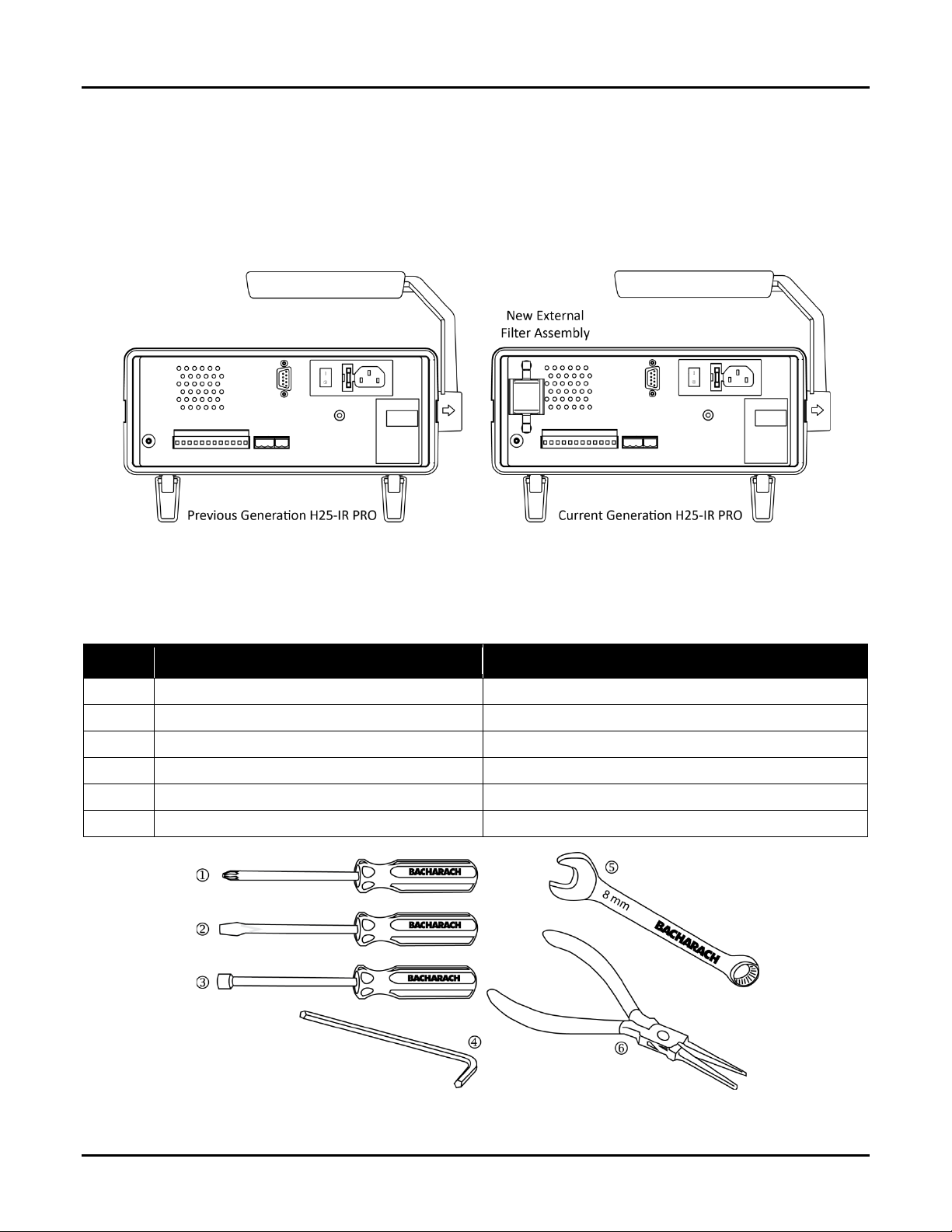
The previous generation of the H25-IR Pro leak detector had an internal filter that required disassembly for replacement.
This was changed in the newer model of the H25-IR Pro to an external filter found at the rear of the instrument. The
purpose of this document is to explain the procedure for upgrading an older-style H25-IR Pro leak detector to include the
newer external filter.
Figure 1-1. Back Panel Comparison of Previous and Current Generations of the H25-IR Pro
1.2. Required Tools
The following items are required to complete the retrofit.
Item Description Function
3 ¼” wrench or nut driver RS-232 connector removal
6 Needle nose pliers Aid in connecting the sample entry tubing
Figure 1-2. Tools Required to Complete the H25-IR Pro External Filter Retrofit
2 P/N: 3015-9004 Rev 0
Page 3
H25-IR PRO External Filter Retrofit
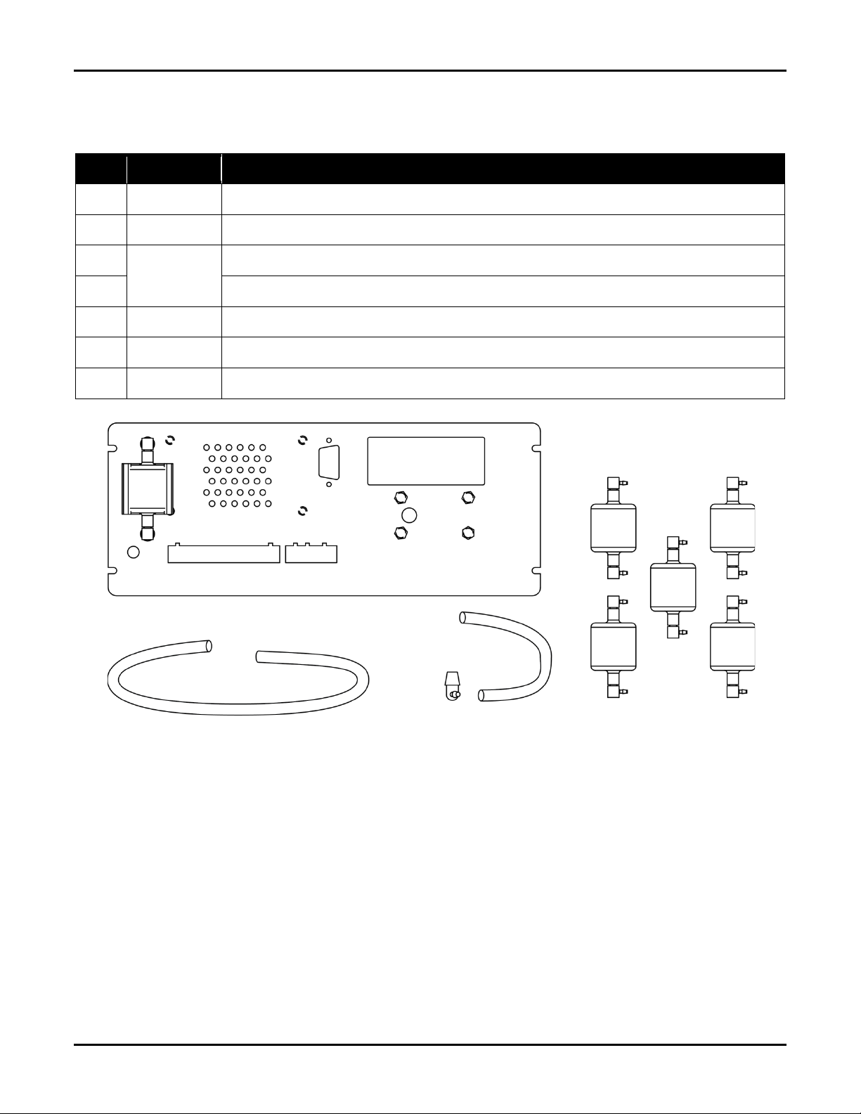
1.3. Retrofit Kit Contents
The H25-IR PRO External Filter Retrofit Kit (P/N 3015-5817) comes with all required new components to adapt the H25-IR
Pro to use the new external filter.
Qty Part Number Description
1 3015-5815 New rear panel; includes 1 new filter (P/N 3015-5816)
1 3015-5818 5-pack of additional new filters (pack of 5 of 3015-5816)
17 in
0003-6372
7 in Silicon tubing (1/16” ID x 1/8” OD) for return line to internal reducer elbow
1 0103-5288 Barbed reducer elbow (1/8” to 1/16” ID tube) to adapt H25-IR Pro to use the external filter
1 0006-9358 1/16” (1.5 mm) hex key
1 3015-9004 Instructions
Silicon tubing (1/16” ID x 1/8” OD) for inlet line
Figure 1-3. Components of the 3015-5817 Retrofit Kit (Instruction Manual Not Shown)
∇ ∇ ∇
P/N: 3015-9004 Rev 0 3
Page 4

H25-IR PRO External Filter Retrofit
SECTION 2: REPLACEMENT PROCESS
2.1. Rear Plate Removal
Step Description
1 Unplug the AC power cord.
2 Unplug the probe assembly.
Remove the front and rear
3
bezel by gently pulling at the
left or right center point.
Remove the top chassis
screws at the front and back.
4
Pry up on the chassis lid and
remove.
With the rear of the chassis
facing you, remove all three
5
terminal blocks by pulling
straight out.
Disconnect the RS232 and
6
audio PCB ribbon connectors.
4 P/N: 3015-9004 Rev 0
Page 5

H25-IR PRO External Filter Retrofit
chassis.
Step Description
Disconnect the AC power
7
entry module wires, noting
the wire color and position.
Remove the two lower chassis
8
screws.
Carefully pull the rear plate
9
away from the back of the
Locate the exhaust tube port
inside the instrument, where
it exits. Pull the tubing off the
10
barbed fitting. The rear plate
will now be free from the
instrument.
2.2. Part Transfer to New Plate
Step Description
Using the tools described earlier, remove and reinstall the speaker, RS-232, exhaust port barbed fitting, and
1
audio PCB onto the new rear plate. Connect the speaker as required.
The AC power entry module is removed by pressing the springs on each side inward until they are flat. Do this
while pressing down on the module to aid release. The terminal blocks removed earlier may be used as a
2
support for the plate while the power entry module is removed. As soon as one side is released the other side
will release easily.
Insert the power entry module in the new rear plate, noting that the power switch is to the right, and the
3
ground pin is up.
2.3. Installation of New Plate
Step Description
1 Installation is generally the reverse of the removal steps.
2 It is recommended that the exhaust tube be connected first.
Align the new rear plate to the instrument PCB terminal strip. Insert the terminal blocks to aid holding the plate
in place.
3
NOTE: Ensure the new filter tubing is not pinched, kinked, or trapped between any components.
4 Reconnect the audio PCB, RS232, and power entry module wires.
2.4. Tubing Changes
Step Description
1 Locate the 25 mm diameter filter and sample inlet tubing. The tubing is 1/8” (3 mm) silicone.
2 Disconnect the filter from the larger tubing nearest the main PCB.
P/N: 3015-9004 Rev 0 5
Page 6

H25-IR PRO External Filter Retrofit
Figure 2-1. Internal Tubing Comparison of Previous and Current Generations of the H25-IR Pro
6 P/N: 3015-9004 Rev 0
Page 7

H25-IR PRO External Filter Retrofit
Step Description
3 Disconnect the sample inlet tubing from the inlet fitting by pulling gently.
Locate the 17” (432 mm) long piece of tubing preinstalled on the new rear plate / external filter. The tubing is
entering near the top of the ear plate, and has no other fitting attached. Thread this toward the front of the
4
instrument and connect to the sample entry fitting. Needle nose pliers may help with this step. Ensure the
tubing and electrical connections are not damaged.
Twist the tubing on the tee next to where the internal filter was connected, so that the tubing stub is pointing
5
upward. See the photos below.
Locate the 7” (178 mm) long piece of tubing with attached elbow fitting, preinstalled on the new rear plate /
6
external filter. The tubing is entering near the bottom of the ear plate. Thread the tubing and mate the elbow
fitting to the tubing stub from the last step.
When finished there should be 1” to 2” (25 mm to 50 mm) of extra tubing to the external filter. Adjust the
7
tubing route if needed to ensure some slack tubing is present.
8 Confirm all electrical and tubing connections are made.
9 Replace the chassis lid and bezels.
∇ ∇ ∇
P/N: 3015-9004 Rev 0 7
Page 8

H25-IR PRO External Filter Retrofit
SECTION 3: MAINTENANCE
3.1. Replacing the External Filter
Step Description
1 Turn off power.
Grasp the filter housing and rotate the top back and down, twisting the filter out of the mounting clip. Use
2
caution as the clip has high force. Do not pull the filter away further than 2” (50 mm) from the back of the
instrument. If the tubing becomes taut, move the filter closer to the instrument.
With the filter free of the clip, disconnect the top tubing from the fitting. Install the new filter, noting the proper
3
orientation (shown below).
4 Repeat for the lower tubing. Dispose of the used filter.
Install the filter in the opposite manner to removal. Start with the filter at an angle, with the lower part pressed
5
into the clip. Guide the tubing through the rear plate as needed to ensure the tubing isn’t kinked. Rotate the
filter inward and upward into the clip. As the top of the filter enters the clip it will be strongly pulled in.
6 Double check the tubing, ensuring it is fully seated on the elbow fittings and is not kinked or pinched.
Figure 3-1. Back Panel of the H25-IR Pro Showing the External Filter
8 P/N: 3015-9004 Rev 0
Page 9

H25-IR PRO External Filter Retrofit
E-mail: support@BachCan.ca
3.2. Service Centers
Service and replacement parts can be obtained by contacting one of the following Bacharach Service Centers.
United States
Bacharach, Inc.
621 Hunt Valley Circle
New Kensington, PA 15068
Phone: 724-334-5051
Fax: 724-334-5723
Email: help@mybacharach.com
Canada
Bacharach of Canada, Inc.
20 Amber St. Unit #7
Markham, Ontario L3R SP4
Canada
Phone: 905-470-8985
FAX: 905-470-8963
∇ ∇ ∇
P/N: 3015-9004 Rev 0 9
Page 10

H25-IR PRO External Filter Retrofit
621 Hunt Valley Circle, New Kensington, PA 15068
Printed in U.S.A. ® Registered Trademark of Bacharach Inc.
Website: www.mybacharach.com • E-mail: help@mybacharach.com
Headquarters:
10 P/N: 3015-9004 Rev 0
 Loading...