

Bacharach GDX-350 Owner's Manual

GDX-350 Sensor Transmitter
Instruction 5600-9001
Installation • Operation • Maintenance
Rev. 2 – October 2012
Product Leadership • Training • Service • Reliability

GDX-350 Sensor Transmitter
WARRANTY
Bacharach, Inc. warrants to Buyer that at the time of delivery this Product will be free from defects in material and
manufacture and will conform substantially to Bacharach Inc.'s applicable specifications. Bacharach's liability and
Buyer's remedy under this warranty are limited to the repair or replacement, at Bacharach's option, of this Product or
parts thereof returned to Seller at the factory of manufacture and shown to Bacharach Inc.'s reasonable satisfaction
to have been defective; provided that written notice of the defect shall have been given by Buyer to Bacharach Inc.
within two (2) years after the date of delivery of this Product by Bacharach, Inc.
Bacharach, Inc. warrants to Buyer that it will convey good title to this Product. Bacharach's liability and Buyer's
remedy under this warranty of title are limited to the removal of any title defects or, at the election of Bacharach, to
the replacement of this Product or parts thereof that are defective in title.
The warranty set forth in paragraph 1 does not apply to parts the Operating Instructions designate as having a limited
shelf-life or as being expended in normal use (e.g., filters).
THE FOREGOING WARRANTIES ARE EXCLUSIVE AND ARE GIVEN AND ACCEPTED IN LIEU OF (I) ANY AND
ALL OTHER WARRANTIES, EXPRESS OR IMPLIED, INCLUDING WITHOUT LIMITATION THE IMPLIED
WARRANTIES OF MERCHANTABILITY AND FITNESS FOR A PARTICULAR PURPOSE: AND (II) ANY
OBLIGATION, LIABILITY, RIGHT, CLAIM OR REMEDY IN CONTRACT OR TORT, WHETHER OR NOT ARISING
FROM BACHARACH'S NEGLIGENCE, ACTUAL OR IMPLIED. The remedies of the Buyer shall be limited to those
provided herein to the exclusion of any and all other remedies including, without limitation incidental or consequential
damages. No agreement varying or extending the foregoing warranties, remedies or this limitation will be binding
upon Bacharach, Inc. unless in writing, signed by a duly authorized officer of Bacharach.
Register your warranty by visiting
www.MyBacharach.com
NOTICE
Product improvements and enhancements are continuous; therefore the specifications and information
contained in this document may change without notice.
Bacharach, Inc. shall not be liable for errors contained herein or for incidental or consequential damages
in connection with the furnishing, performance, or use of this material.
No part of this document may be photocopied, reproduced, or translated to another language without the
prior written consent of Bacharach, Inc.
Copyright © 2012, Bacharach, Inc., All Rights Reserved
®
BACHARACH
service marks and logos referenced herein belong to their respective owners.
2 P/N: 5600-9001 Rev 2
is a registered trademark of Bacharach, Inc. All other trademarks, trade names,

GDX-350 Sensor Transmitter
TABLE OF CONTENTS
1.
OVERVIEW ........................................................................................................................................... 5
1.1. Stand-alone and Wired Networks ............................................................................................ 5
1.2. RF Wireless Networks ............................................................................................................. 6
1.3. The RF Transmitter and Client/Server Wireless Networks ...................................................... 7
1.3.1 Radio Status Icons ( ) .................................................................. 7
1.3.2 RF Comm Cycle and Conserving Battery Life.............................................................. 8
1.3.3 RF BATTERY I/O PCB WITH POWER SWITCH ......................................................... 8
1.3.4 900 MHz RF Module ..................................................................................................... 9
1.4. Safety Information – Read Before Installation and Applying Power ...................................... 10
1.5. Ordering Information .............................................................................................................. 11
1.6. Replacement Parts and Accessories ..................................................................................... 13
1.7. Calibration Gas ...................................................................................................................... 14
1.8. System Design Specifications ............................................................................................... 14
1.9. General Specifications ........................................................................................................... 15
1.10. Sensor Specifications ............................................................................................................ 16
2. INSTALLATION INSTRUCTIONS ...................................................................................................... 17
2.1. Sensor Location ..................................................................................................................... 17
2.2. Mounting the Enclosure ......................................................................................................... 17
2.2.1 Stand-alone and Wired Networks ............................................................................... 17
2.2.2 RF Wireless Networks ................................................................................................ 18
Transmission Range: 4-20mA Signals ................................................................................. 20
2.3.
2.4. Transmission Range: RF Antenna Signals ........................................................................... 20
2.5. Antenna Selection and Location ............................................................................................ 21
2.6. Water Proofing Antenna Connection ..................................................................................... 22
2.7. System Grounding ................................................................................................................. 22
2.8. 3-Wire 4-20 mA Mode Installation ......................................................................................... 22
2.9. Alarms/RS-485 Modbus Option Installation ........................................................................... 23
2.10. Isolated 4-20 mA Output Option ............................................................................................ 26
2.11. Sensor Installation ................................................................................................................. 26
3. INITIAL START-UP ............................................................................................................................. 28
3.1. Model Name ........................................................................................................................... 28
3.2. Initial Toxic/Oxygen Sensor Monitor Start-Up ........................................................................ 28
3.3. Initial Toxic/Oxygen Sensor Monitor “Span” Check ............................................................... 28
4. OPERATING INSTRUCTIONS ........................................................................................................... 29
4.1. Routine Sensor Calibrations .................................................................................................. 29
4.2. Alarm Operation ..................................................................................................................... 31
4.3. Alarm 3 – Understanding Fault/Level Operation ................................................................... 31
5. SETUP MENU CONFIGURATION ..................................................................................................... 33
5.1. Menus Database Configuration ............................................................................................. 33
5.2. Configuration Using the Magnetic Wand ............................................................................... 35
5.3. System Configuration Menus ................................................................................................. 35
5.4. Alarm Settings ........................................................................................................................ 37
5.5. Relay Configuration (If Equipped) .......................................................................................... 39
5.6. Sensor Information ................................................................................................................. 39
5.7. Clock/Delay Setup ................................................................................................................. 40
5.8. Communications Setup (RF Communications)...................................................................... 40
5.9. Base Stations ......................................................................................................................... 42
5.10. System Security ..................................................................................................................... 43
5.11. LCD Contrast Adjustment ...................................................................................................... 43
5.12. HELP Screen ......................................................................................................................... 44
P/N: 5600-9001 Rev 2 3

GDX-350 Sensor Transmitter
5.13. Diagnostics ............................................................................................................................ 44
5.14. RS-485/Modbus Setup ........................................................................................................... 44
5.15. Modbus Register and Function Code Summary .................................................................... 45
5.16. System Security ..................................................................................................................... 49
6. SERVICE CENTER ............................................................................................................................. 49
∇ ∇ ∇
4 P/N: 5600-9001 Rev 2
GDX-350 Sensor Transmitter
1. OVERVIEW
1.1. Stand-alone and Wired Networks
The GDX-350 is a fixed-point monitor designed to provide continuous monitoring of hazardous gases in
the workplace. Monitored values are displayed in their engineering units as well as graphically such as
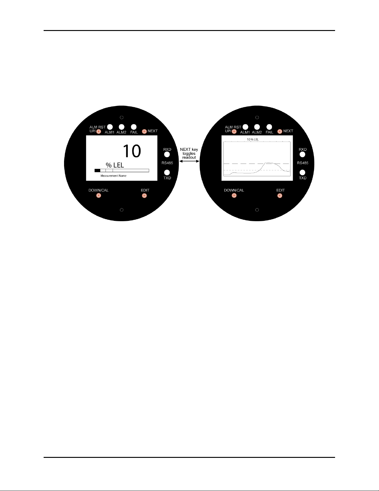
bar graphs or 30-minute trends (see Figure 1-1).
Figure 1-1: Engineering Units Data Displays: Bar Graph (Left), 30-Minute Trend (Right)
Input types include electrochemical toxic and oxygen sensors, catalytic bead combustible sensors, MOS
solid-state sensors, as well as various millivolt, volt and 4-20 mA inputs. Sensors supplied by the factory
include an 8-wire Smart Sensor interface capable of configuring data uploads to the GDX-350.
Traditional 3-wire Simple sensors, without the smart interface, are also supported by the GDX-350. Its
advanced microcontroller electronics and superior graphic LCD operator interface offer enhanced
diagnostics and fault analysis not possible in competing products. The GDX-350 provides a standard
4-20 mA output signal for connection to control systems or other alarm instrumentation. Available options
include an Alarm Relay/RS-485-Modbus board or an isolated 4-20 mA output. Non-volatile memory
retains all configuration data during power interruptions. The magnetic, non-intrusive calibration can be
easily performed by a single person without opening the enclosure. A standard Real Time Clock and
Calendar feature allows data logging of calibrations and alarm events for recall to the LCD readout or
over the serial port.
Only periodic calibration checks are needed to assure dependable performance. The operator interface
is very intuitive with the LCD displaying data both graphically as bar-graphs/trends as well as in
engineering units (Figure 1-1). Additional features include:
• No potentiometer or jumper settings required. All setup is completed through display menus
accessed via the LCD/magnetic keypad operator interface without opening the enclosure.
• Field adjustable alarm levels may be high, low, fault, fail-safe, latching and acknowledgeable.
• New alarms cause front LEDs to flash and become steady after acknowledgement.
• CAL MODE advises when to apply gas during calibrations.
• One half-hour trend screen shows rate of change of gas exposures.
• Sensor life bar-graph automatically updates after each SPAN calibration.
• Modular design allows for efficient installation as well as plug in sensors that allow a change in target
gas after installation
• New smart sensors are recognized by the GDX-350 and prompt users to either upload new
configuration data or continue with data from the previous smart sensor.
• Sensors are industry proven for fast response and long life.
P/N: 5600-9001 Rev 2 5

GDX-350 Sensor Transmitter
1.2. RF Wireless Networks
IMPORTANT: This section describes GDX-350 RF toxic / oxygen monitors equipped with
the RF Wireless Interface and RF firmware. This battery powered device has no external
power or signal wiring and is limited to self powered electrochemical sensors for toxic and
oxygen measurements. Gas values are displayed in their engineering units as well as
graphically as bar graphs or 30-minute trends. Flashing front panel LEDs notify personnel
when alarm levels have been reached. Periodic calibration checks are needed to assure
The RF version of the GDX-350 functions on a license free 900MHz or 2.4GHz wireless Client / Server
networks and transmits monitored data to GDA-400 and GDA-1600 controllers. Controllers must be
equipped with the matching RF wireless modem and appropriate antenna to receive the transmissions.
Up to sixteen GDX-350 wireless monitors may communicate to one GDA-1600 and up to four to a GDA-
400. Wireless networks requiring more than 16 points may consist of multiple controllers.
Advanced microcontroller electronics and superior graphic LCD operator interface offers enhanced
diagnostics and fault analysis not possible in competing products. Non-volatile memory retains all
configuration data during power interruptions. The magnetic keypad allows non-intrusive calibrations be
performed by one person without opening the enclosure. A “real time clock & calendar” feature allows
logging of calibrations, alarm trips, communication faults and other events for review on the LCD readout.
Compatible sensors include an 8-wire Smart Sensor interface capable of configuration data uploads to
the monitor. Traditional Simple sensors without the smart interface are also supported. A separate PC
compatible USB Interface device allows Smart sensors to be loaded with configuration variables via a PC
and upload this data to the GDX-350. This configuration data includes alarm set points, range, target gas,
calibration constants and other variables required to match a specific application. For Simple sensors
without the smart interface, the USB device allows direct GDX-350 configuration from a PC.
dependable performance.
Additional features include:
• On screen radio status icons indicate “Server In Range”, “Server Out of Range”, “Server
Previously Out of Range” and “Low Battery” conditions.
• No potentiometer or jumper settings required. All setup is with menus accessed via the LCD /
magnetic keypad operator interface without opening the enclosure.
• Field adjustable alarm levels flash front panel LED indicators for HIGH, WARN, FAIL conditions.
Alarm relays are not available with this low power model.
• CAL MODE provides on-screen prompts when to apply cal gas during calibrations.
• “Sensor life” bar-graph updates after each SPAN calibration indicating when to replace old
sensors.
• Half hour trend screen shows rate of change of gas exposures.
• Modular design affords efficient installation and plug in sensors allow changing target gases even
after installation.
• New smart sensors are recognized by the GDX-350 which prompts users to either upload new
configuration data or continue with data from the previous smart sensor.
• Missing sensors trip the FAIL alarm.
• Compatible sensors are industry proven for fast response and long life.
6 P/N: 5600-9001 Rev 2

GDX-350 Sensor Transmitter
Figure 1-2: Data Displays (RF Version) SHOWING Radio Status
1.3. The RF Transmitter and Client/Server Wireless Networks
Wireless transceivers utilize a FHSS (Frequency Hopping Spread Spectrum) Server-Client network where
multiple
the beginning of every frequency hop (50 times per second). Client transceivers listen for this beacon and
upon receiving it synchronize their hopping with the Server. Since RF GDX-350s are powered by a small
battery, much care is taken to reduce power consuming RF transmissions to a minimum. For this reason
RF-configured GDX-350s are unsuitable for Server operation and are always Clients.
Each GDX-350 wireless “broadcast” includes 10-bit monitored gas value, battery voltage and a status
byte. This proprietary wireless protocol interfaces only to GDA-400 and GDA-1600 controllers.
Controllers are capable of functioning as Clients
network. Multiple controllers may receive the same transmissions from RF-configured GDX-350s, but only
one controller per wireless network may be configured as the Server.
Each transceiver on a wireless network must have its RADIO SETUP menus configured to share the
same Hop Channel (0-32) and System ID (0-255) in order to communicate. There should never be two
servers with the same Hop Channel / System ID settings in the same coverage area as the interference
between the two servers will severely hinder RF communications. The Server must be in a powered
location and should be centrally located since all Clients must receive the server’s beacon in order to
communicate.
Correct planning and design of wireless systems are imperative for ensuring a successful installation. It is
highly recommended that a site drawing indicating location of monitors and base station, line of site
obstructions, and sources of RF interference be submitted when requesting a quotation.
clients synchronize their frequency hopping to a single server
or
Servers, but only one Server is allowed per wireless
. The Server transmits a beacon at
1.3.1 Radio Status Icons ( )
Figure 2-1 shows the data displays and identifies “radio status” (RS) icons which appear on the LCD of
RF-configured GDX-350s. RS icons, along with the TXD led (see Figure 1-2), are useful diagnostic tools
for evaluating RF communication. Status conditions indicated by the RS icon are Sleep Mode - Zzz’s,
Server In Range -
(server’s beacon not received at most recent attempt), Server Previously Out of Range - and Low
Battery -
. The Server “Previously Out of Range” icon is useful in determining if intermittent
communication failures are a result of this monitor having problems receiving the Server’s beacon. The
duration and frequency of “out of range” conditions are stored in the Event Log table. Low Battery
conditions also flash the FAIL LED.
It is important to understand RS icons only update as the TXD LED flashes indicating an RF transmission
has occurred. The adjustable (see Wakeup Time menu) RF transmission rates are typically each 5minutes, but increase to each 6-seconds during alarm conditions.
P/N: 5600-9001 Rev 2 7
(server’s beacon received at most recent attempt), Server Out of Range -
GDX-350 Sensor Transmitter
30s. Battery life is
1.3.2 RF Comm Cycle and Conserving Battery Life
Most of the GDX-350’s battery power is consumed as the radio communicates to the wireless network.
Each Comm cycle consists of the following operations: Awake the radio in receive mode; listen for the
Server’s beacon; synchronize to the Server’s hopping frequency to become “In Range
packet out the antenna and return to sleep mode. This sequence takes from 0.25 to 1 second to
complete. If the radio fails to synchronize hopping upon the initial attempt, it waits 6 seconds and tries
again, then waits 6 seconds and tries once more. If the third attempt fails, the “Out of Range
appears and the GDX-350 returns to its Comm cycle. Out of Range will also be logged into the Event
Log. Transmit power levels are adjustable (900MHx models only) and the lower the power setting the
longer the battery will last.
Every 6-seconds, the monitor performs a “sniff test” to detect level of target gas present at the sensor. At
each “sniff test”, the Zzz’s “Sleep Mode” icon is briefly replaced by an RS icon. At this time the readout
radio
updates to indicate gas value measured at the “sniff test.” The
stays OFF if the gas value does not
trip A1 or A2 alarms. Except when the Wakeup Time menu expires (maximum of 5-minutes) the radio
turns on, receives the Server’s beacon, and transmits its data. These routine transmissions allow the
controllers to confirm a good wireless comm link even when no alarms exist. If A1 or A2 alarms do exist
during the “sniff test”, the radio wakes, receives the Server’s beacon, and transmits its data immediately.
The following list identifies each of the conditions that cause the radio to transmit:
• Every 5-minutes (or faster depending upon Wakeup Time menu) when there is no A1 or A2
alarm.
IMPORTANT: The receiving controller reports “Comm Error” if the monitor does not
reply for periods of greater than 18-minutes. A3 and FAIL alarms do not increase radio
transmission rates.
• Every 6-seconds if there is an A1 or A2 level alarm.
• Upon entry into CAL MODE a 75 counts value (-15.6% FS) is transmitted. Receivers indicate “IN
CAL” when 75 counts is the input for a channel (200 to 1000 counts represents 0 to 100% of full
scale).
• Upon ENTRY into CAL PURGE a 200 counts value (0% FS) is transmitted.
NOTE: To prevent A1 & A2
low trip alarms, oxygen
ranges transmit 20.9% readings upon entry
into CAL PURGE.
• Holding the magnet to the UP key for >8 seconds forces a transmission of the current reading
value.
”; transmit data
” icon
1.3.3 RF BATTERY I/O PCB WITH POWER SWITCH
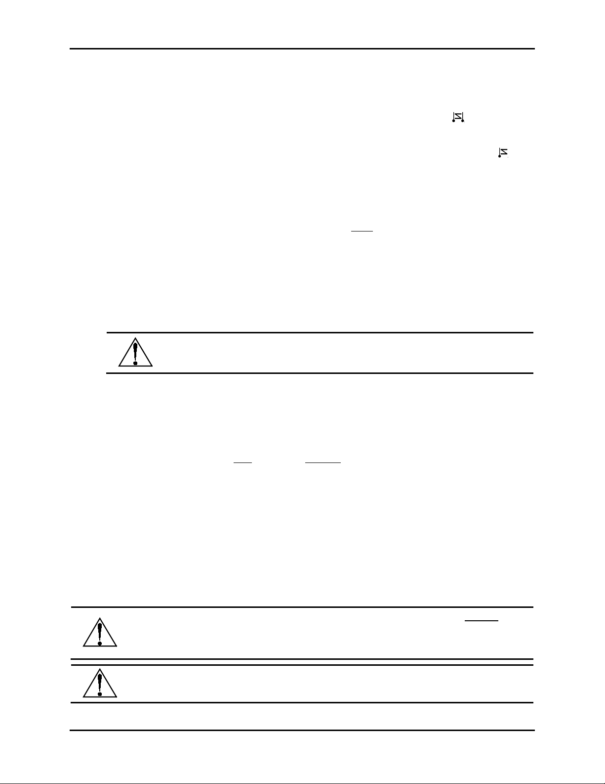
The RF electronics consists of the lower Battery I/O PCB (Figure 1-3) connected by a cable to the upper
Display assembly with RF Module PCB (Figure 1-4). The 3.6 volt lithium ‘D’ cell battery will continuously
power the unit for up to one year and may be replaced by following the procedure in Figure 1-3.
Power switch (SW1), on the Battery PCB, applies battery power to the RF monitor. SW1 should be OFF if
the monitor is to be out of service for long periods.
IMPORTANT: Do not turn SW1 ON until the controller designated as
operational and ready to communicate to the RF-equipped GDXreduced if the RF-equipped GDX-30 is on for long periods while unable to communicate to
the Server controller.
IMPORTANT: DO NOT ATTEMPT TO CHARGE THIS BATTERY OR REPLACE WITH
ANY OTHER THAN THE APPROPRIATE PART FROM BACHARACH.
8 P/N: 5600-9001 Rev 2
Server is fully
GDX-350 Sensor Transmitter
Figure 1-3: Battery I/O PCB
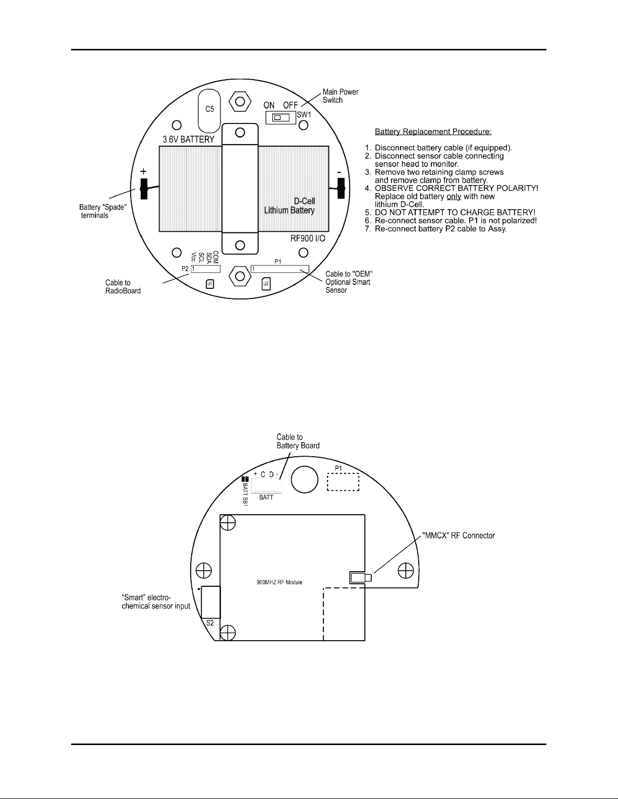
1.3.4 900 MHz RF Module
The RF-equipped GDX-350’s RF module mounts “piggy back” to the back of the Display assembly as
shown in Figure 1-4. The MMCX RF connector connects to the antenna fitting’s pigtail coax cable. There
is also a slender 4 conductor cable between the RF Module PCB and the battery I/O PCB bolted to the
bottom of the enclosure.
Figure 1-4: RF Module PCB
P/N: 5600-9001 Rev 2 9
GDX-350 Sensor Transmitter
1.4. Safety Information – Read Before Installation and Applying Power
IMPORTANT: Users should have a detailed understanding of GDX-350 operating and
maintenance instructions. Use the GDX-350 only as specified in this manual otherwise
the detection of gases and resulting protection provided may be impaired. Read the
following WARNINGS prior to use.
WARNING: Calibrate with known target gas at start-up and check on a regular schedule,
at least every 90 days. More frequent inspections are encouraged to spot problems such
as dirt, oil, paint, grease or other foreign materials on the sensor head.
WARNING: Do not use the GDX-350 if its enclosure is damaged or cracked or has
missing components.
WARNING: Make sure the cover, internal PCBs, antenna, and field wiring connections
are securely in place before operation.
WARNING: Use only a sensor assembly compatible with the GDX-350 and approved by
Bacharach, Inc.
WARNING: Periodically test for correct operation of the system’s alarm events by
exposing the monitor to a targeted gas concentration above the High Alarm set point.
WARNING: Do not expose the GDX-350 to electrical shock or continuous severe
mechanical shock.
WARNING: Protect the GDX-350 from dripping liquids and high power sprays.
WARNING: Use only for applications described within this manual.
CAUTION: Do not paint the sensor assembly or the transmitter.
CAUTION: For safety reasons this equipment must be operated and serviced by qualified
personnel only. Read and understand instruction manual completely before operating or
servicing.
10 P/N: 5600-9001 Rev 2

1.5. Ordering Information
Transmitter
Description
GDX-350 CO
GDX-350 H2S
GDX-350 O2
GDX-350 NO2
GDX-350 NH3
GDX-350 SO2
Part
Number
5600-301x
5601-301x
5600-302x
5601-302x
5600-303x
5601-303x
5600-304x
5601-304x
5600-305x
5601-305x
5600-306x
5601-306x
GDX-350 Sensor Transmitter
Options
x=1 3-wire base w/ 4-20 mA output
x=2 3-wire base w/ 4-20 mA output and Modbus
x=1 2-wire base
x=8 2-wire base w/ 900 MHz wireless
x=9 2-wire base w/ 2.4 GHz wireless
x=1 3-wire base w/ 4-20 mA output
x=2 3-wire base w/ 4-20 mA output and Modbus
x=1 2-wire base
x=8 2-wire base w/ 900 MHz wireless
x=9 2-wire base w/ 2.4 GHz wireless
x=1 3-wire base w/ 4-20 mA output
x=2 3-wire base w/ 4-20 mA output and Modbus
x=1 2-wire base
x=8 2-wire base w/ 900 MHz wireless
x=9 2-wire base w/ 2.4 GHz wireless
x=1 3-wire base w/ 4-20 mA output
x=2 3-wire base w/ 4-20 mA output and Modbus
x=1 2-wire base
x=8 2-wire base w/ 900 MHz wireless
x=9 2-wire base w/ 2.4 GHz wireless
x=1 3-wire base w/ 4-20 mA output
x=2 3-wire base w/ 4-20 mA output and Modbus
x=1 2-wire base
x=8 2-wire base w/ 900 MHz wireless
x=9 2-wire base w/ 2.4 GHz wireless
x=1 3-wire base w/ 4-20 mA output
x=2 3-wire base w/ 4-20 mA output and Modbus
x=1 2-wire base
x=8 2-wire base w/ 900 MHz wireless
x=9 2-wire base w/ 2.4 GHz wireless
P/N: 5600-9001 Rev 2 11

GDX-350 Sensor Transmitter
Transmitter
Description
Part
Number
5600-307x
GDX-350 PH3
5601-307x
5600-311x
GDX-350 H2
5601-311x
GDX-350 CH4
(Catalytic)
GDX-350 CH4
(IR)
5600-320x
5600-321x
GDX-350 CO2 5600-322x
GDX-350 C3H3
(IR)
5600-323x
Options
x=1 3-wire base w/ 4-20 mA output
x=2 3-wire base w/ 4-20 mA output and Modbus
x=1 2-wire base
x=8 2-wire base w/ 900 MHz wireless
x=9 2-wire base w/ 2.4 GHz wireless
x=1 3-wire base w/ 4-20 mA output
x=2 3-wire base w/ 4-20 mA output and Modbus
x=1 2-wire base
x=8 2-wire base w/ 900 MHz wireless
x=9 2-wire base w/ 2.4 GHz wireless
x=1 3-wire base w/ 4-20 mA output
x=2 3-wire base w/ 4-20 mA output and Modbus
x=1 3-wire base w/ 4-20 mA output
x=2 3-wire base w/ 4-20 mA output and Modbus
x=1 3-wire base w/ 4-20 mA output
x=2 3-wire base w/ 4-20 mA output and Modbus
x=1 3-wire base w/ 4-20 mA output
x=2 3-wire base w/ 4-20 mA output and Modbus
12 P/N: 5600-9001 Rev 2

GDX-350 Sensor Transmitter
1.6. Replacement Parts and Accessories
Part Number Description
5600-0004 GDX Calibration Cup/Sample Draw Adaptor
5600-0003 GDX Splash Guard/Remote Cal-Cup
0024-7059 Calibration Kit – Regulator, Tubing, and Carrying Case (no gas included)
5600-5010 CO Uncalibrated Sensor Module
5600-6010 CO Pre-Calibrated Smart Sensor Module
5600-5020 H2S Uncalibrated Sensor Module
5600-6020 H2S Pre-Calibrated Smart Sensor Module
5600-5030 O2 Uncalibrated Sensor Module
5600-6030 O2 Pre-Calibrated Smart Sensor Module
5600-5040 NO2 Uncalibrated Sensor Module
5600-6040 NO2 Pre-Calibrated Smart Sensor Module
5600-5050 NH3 Uncalibrated Sensor Module
5600-6050 NH3 Pre-Calibrated Smart Sensor Module
5600-5060 SO2 Uncalibrated Sensor Module
5600-6060 SO2 Pre-Calibrated Smart Sensor Module
5600-5070 PH3 Uncalibrated Sensor Module
5600-6070 PH3 Pre-Calibrated Smart Sensor Module
5600-5200 CH4 (CAT) Uncalibrated Sensor Module
5600-6200 CH4 (CAT) Pre-Calibrated Smart Sensor Module
5600-5210 CH4 (IR) Uncalibrated Sensor Module
5600-6210 CH4 (IR) Pre-Calibrated Smart Sensor Module
5600-5220 CO2 Uncalibrated Sensor Module
5600-6220 CO2 Pre-Calibrated Smart Sensor Module
5600-5110 H2 Uncalibrated Sensor Module
5600-6110 H2 Pre-Calibrated Smart Sensor Module
5600-5330 C3H8 Uncalibrated Sensor Module
5600-6330 C3H8 Pre-Calibrated Smart Sensor Module
P/N: 5600-9001 Rev 2 13
GDX-350 Sensor Transmitter
1.7. Calibration Gas
Part Number Gas Name Chemical Formula Concentration
0051-4000 Ammonia NH3 25 PPM
0051-4028 Propane C3H8 25% LEL
0051-4031 Methane CH4 25% LEL
0051-4010 Carbon Dioxide CO2 2.50%
0051-4052 Phosphine PH3 1 PPM
0051-4040 Hydrogen H2 100 PPM
0051-4048 Nitrogen Dioxide NO2 5 PPM
0051-4075 Sulfur Dioxide SO2 5 PPM
0051-4044 Hydrogen Sulfide H2S 25 PPM
0051-4049 Oxygen O2 20.9%
0051-4025 Carbon Monoxide CO 100 PPM
1.8. System Design Specifications
Category System Design Specification
Supply Voltage
10 to 30 volts
Power
Consumption
Memory
Loop
Resistance
Relays
(Optional)
• With a typical 0.5 watt Bridge Sensor: 100 mA @ nominal 24 VDC
• Relays/RS-485 Modbus Option Board: 40 mA per relay (120 mA total with all 3
energized); RS-485 use adds 20 mA
Non-volatile E2 memory retains configuration values on power outages.
750 ohms maximum (at nominal 24 VDC power)
Three configurable form C (SPDT) relays rated for 5 amp at 30 VDC or 240 VAC
RESISTIVE
.
Relay 1 and Relay 2 level alarms may be configured for HIGH or LOW trip, for
normally energized (Failsafe) or normally de-energized and for latching or nonlatching.
Relay 3 is always normally energized for failsafe operation; therefore, loss of
power to the GDX-350 will be indicated as a “FAULT” condition.
CAUTION: Relays are rated for RESISTIVE loads. Inductive loads, such as contactor coils
or motors may cause contact arcing, which emits RFI into the sensor signals. Use
appropriate snubbers and MOVs across inductive loads and keep wiring away from signal
wires.
14 P/N: 5600-9001 Rev 2

1.9. General Specifications
Category General Specifications
Product Type
Coverage
Front Panel
Housing
Security mode
Calibration
4-20 output Signal
Alarm relays
Communications
Power Safety Mode
Operating Temp
Ambient Humidity
Power
Certification
Warranty
RF Specifications
GDX-350 transmitter/monitor for various gases.
Single sensor, 40 foot diameter
5 Indicator lights; AL1, AL2, Fail, In Cal, and RS-485 TXD and RXD
64 x 128 Pixel LCD graphic display for gas readings, 30 minute trend, bar
graphing, engineering units, and backlight
Instrument enclosure suitable for Class 1, Div 1 and 2, Gr. B, C, and D
Locks out critical parameters
Non-intrusive calibration
3-wire, 4-20 mA. Max loop resistance is 750 ohms (@24 VDC)
Three configurable form C (SPDT) relays rated for 5 amp at 30 VDC or
240 ~VAC RESISTIVE.
Relay 1 and Relay 2 level alarms are configurable for HIGH or LOW trip, for
normally energized (Failsafe) or normally de-energized and for latching or nonlatching.
Relay 3 is always normally energized for failsafe operation so loss of power to
the unit will be indicated as a “FAULT” condition.
RS-485, Modbus optional, 4-20 mA standard
Fully automatic system reset. All programmed parameters retained
-55 to 60 °C (-67 to 140 °F)
5% to 90% RH (non-condensing)
10 – 30 VDC, 250 mA (@ 24 VDC)
CSA certified for Division 1 and 2 hazardous area installations for explosion
proof Class 1 Groups B, C, and D, and intrinsically safe (GDX-350/EC 2-wire
loops only) Class 1 Groups A, B, C, and D.
Designed to meet CSA C22.2 No.152 for Combustibles Monitors and ISA
92.0.01 Part 1 for Toxic Monitors (excludes ammonia). Ammonia is for use in
non-classified areas only. ATEX: CE, EExd IIB + H2, T5
2 years from date of shipment, consumables not included
Power Supply: Integral non-rechargeable 3.6 volt 19AH lithium D
Power Consumption: <2mA during “sleep” mode, 40mA during “receive
Transmit (TX) Power: 30dBm at highest 1W power setting. Transmit power
Receive (RX) Sensitivity: -100 dBm
Radio Frequency: Hopping occurs between 902 MHz and 928 MHz.
Memory: Non-volatile E
GDX-350 Sensor Transmitter
cell battery.
beacon” mode, up to 1 amp during 1 watt “transmit”
mode. Transmit power may be set from 10mW to 1
watt.
may be set from 10mW to 1 watt
2
memory retains configuration values
in the event of power outages.
P/N: 5600-9001 Rev 2 15
 Loading...