

Page 1
Instruction 5209-9000
Operation Manual
Rev. 0 - May 2011
Product Leadership • Training • Service • Reliability
Page 2

GDC-150 Operation Manual
IMPORTANT NOTE
READ AND UNDERSTAND THIS MANUAL PRIOR TO USING THIS INSTRUMENT.
THIS INSTRUMENT SHOULD BE INSPECTED AND PROGRAMMED BY
QUALIFIED AND TRAINED PERSONNEL.
THIS INSTRUMENT HAS NOT BEEN DESIGNED TO BE INTRINSICALLY S AFE IN
HAZARDOUS OR EXPLOSION-RATED ENVIRONMENTS. FOR YOUR SAFETY,
DO NOT
USE OR I NSTALL IT IN AREAS CLASSIFIED AS HAZARDO US AREAS
(E.G., EXPLOSION-RATED ENVI RO NM ENTS).
ii 5209-9000 Rev 0
Page 3

DISCLAIMER
UNDER NO CIRCUMSTANCES WILL BACHARACH, INC. BE LIABLE FOR ANY
CLAIMS, LOSSES OR DAMAGES RESU LTING FROM OR ARISING OUT OF THE
REPAIR OR MODIFICATION OF THIS EQUIPMENT BY A PARTY OTHER THAN
BACHARACH, INC. OR ITS AUTHORI ZED SERVIC E REPRE SENTATIVES, OR BY
OPERATION OR USE OF THE EQUIPMENT OTHER THAN IN ACCORDANCE
WITH THE PRINTED INSTRUCTIONS CONTAINED W ITHIN THIS MANUAL OR IF
THE EQUIPMENT HAS BEEN IMPROPERLY MAINTAINED OR SUBJECTED TO
NEGLECT OR ABUSE. ANY OF THE FORGOING WILL VOID THE WARRANTY.
GDC-150 Operation Manual
WARRANTY POLICY
BACHARACH, INC. WARRANTS THIS INSTRUMENT TO BE FREE FROM
DEFECTS IN MATERIALS AND WORKMANSHIP FOR A PERIOD OF TWO (2)
YEARS FROM THE DATE OF PURCHASE. THIS INCLUD ES ALL ELECTRONICS,
SOLID-STATE SENSORS, CATALYTIC SENSORS, AND ELECTROCHEMICAL
CARBON MONOXIDE (CO) SENSORS. OTHER ELECTROCHEMICAL S ENSORS
ARE WARRANTED FOR ONE YEAR.
THE WARRANTY STATU S WILL BE AFFECTED (VOIDED) I F THE INSTRUMENT
HAS NOT BEEN INSTALLED AND MAINTAINED ACCORDING TO THE
INSTRUCTIONS INDICATED IN THIS MANUAL OR HAS BEEN ABUSED,
DAMAGED (ROUGH HANDLING, MECHANICAL DAMAGE, ELECTRICAL SHOCK
DAMAGE, ETC.) OR MODIFIED IN ANY WAY. THIS INSTRUMENT IS ONLY TO BE
USED FOR THE PURPOSES STATED HEREIN. THIS WARRANTY INDICATES
THE FULL EXTENT OF OUR LI ABILITY AND WE ARE NOT RESPONSI BLE FOR
REMOVAL OR REPLACEMENT COSTS, LOCAL REPAIR COSTS,
TRANSPORTATION COSTS OR CONTINGENT EXPENSE S INCURRED W ITHOUT
PRIOR APPROVAL.
BACHARACH, INC. WILL N O T BE HELD LIABLE FOR INDIRECT, INCIDENTAL OR
CONSEQUENTIAL LOSS OR DAMAGE OF ANY KIND TO EQUIPMENT
CONNECTED, IN ANY WAY, TO THE EQUIPMENT MANUFACTURED BY US.
THIS WARRANTY COVERS EQUIPMENT AND PARTS SOLD TO USERS ONLY BY
AUTHORIZED DISTRIBUTORS, D EALERS, AGENTS OR REPRESENTATIVES, AS
AUTHORIZED AND APPOINTED BY BACHARACH.
DUE TO ONGOING RESEARCH, DEVELOPMENT AND PRODUCT TESTING, THE
MANUFACTURER RESERVES THE RIGHT TO CHANGE SPECIFICATIONS
WITHOUT NOTICE. THE INFORMATION CONTAINED HEREIN IS BASED ON
DATA CONSIDERED ACCURATE. HOW EVER, NO WARRANTY IS EXPRESSED
OR IMPLIED REGARDING THE ACCURACY OF THIS DATA.
ALL GOODS MUST BE SHIPPED TO THE MANUFACTURER BY PREPAID
FREIGHT. ALL RETURNED GOODS MUST BE ACCOMPANIED BY AN RMA
NUMBER.
5209-9000 Rev 0 iii
Page 4

GDC-150 Operation Manual
BACHARACH, INC. MAINTAINS AN INSTRUMENT SERVICE FACILITY AT THE
FACTORY. SOME BACHARACH DISTRIBUTORS / AGENTS MAY ALSO HAVE
REPAIR FACILITIES, HOWEVER, BACHARACH ASSUMES NO LIABILITY FOR
SERVICE PERFORMED BY A NYONE OTHER THAN BACHARACH PERSONNEL.
REPAIRS ARE WARRANTED FOR 90 DAYS AFTER DATE OF SHIPMENT
(SENSORS, PUMPS, FILTERS AND BATTERIES HAVE INDIVIDUAL
WARRANTIES). SHOULD YOUR INSTRUMENT REQUIRE NON-WARRANTY
REPAIR, YOU MAY CONTACT THE DISTRIBUTOR FROM WHOM IT WAS
PURCHASED OR YOU MAY CONTACT BACHARACH DIRECTLY.
IF BACHARACH IS TO DO THE REPAIR WORK, SEND THE INSTRUMENT,
PREPAID, TO BACHARACH, INC. AT THE FOLLOWING ADDRESS.
BACHARACH, INC.
621 HUNT VALLEY CIRCLE
NEW KENSINGTON, PA 15068
ATTENTION: SERVICE DEPARTMENT
ALWAYS INCLUDE YOUR RMA #, ADDRESS, TELE PHONE NUMBER, CONTACT
NAME, SHIPPING/BILLING INFORMATION AND A DESCRIPTION OF THE
DEFECT AS YOU PERCEIVE IT. YOU WILL BE CONTACTED WITH A COST
ESTIMATE FOR EXPECTED REPAI RS PRIOR TO THE PERFORMANCE O F ANY
SERVICE WORK. FOR LI ABILITY REASONS, BACHARACH HAS A POLICY OF
PERFORMING ALL NEEDED REPAIRS TO RESTORE THE INSTRUMENT TO
FULL OPERATING CONDITION.
PRIOR TO SHIPPING EQUIPMENT TO BACHARACH, CONTACT OUR OFFICE
FOR AN RMA # (RETURNED MERCHANDISE AUTHORIZATION). ALL
RETURNED GOODS MUST BE ACCOMPANIED WITH AN RMA NUMBER.
PACK THE EQUIPMENT WELL (IN ITS ORIGINAL PACKING IF POSSIBLE), AS
BACHARACH CANNOT BE HELD RESPONSIBLE FOR ANY DAM AGE INCURRED
DURING SHIPPING TO OUR FACILITY.
COPYRIGHTS: THIS MANUAL IS SUBJ ECT TO COPYRIGHT PROTECTION; ALL
RIGHTS ARE RESERVED UNDER INTERNATIONAL AND DOMESTIC
COPYRIGHT LAWS. THIS MANUAL M AY NOT BE COPIED OR TRANSLATED, IN
WHOLE OR IN PART, IN ANY MANNER OR F ORMAT, WITHOUT THE WRITTEN
PERMISSION OF BACHARACH, INC.
SERVICE POLICY
NOTICES
iv 5209-9000 Rev 0
Page 5

REVISIONS
BACHARACH, INC. MAKES NO WARRANTY OR REPRESENTATION,
EXPRESSED OR IMPLIED INCLUDING ANY W ARRANTY OF MERCHANTABI LITY
OR FITNESS FOR PURPOSE, WITH RESPECT TO THIS MANUAL. ALL
INFORMATION CONTAINED IN THIS MANUAL IS BELIEVED TO BE TRUE AND
ACCURATE AT THE TIME OF PRI NTING. HOWEVER, BACHARACH RESERVES
THE RIGHT TO MAKE CHANGES AT ANY TIME WITHOUT NOTICE. REVISED
COPIES OF THIS MANUAL CAN BE O BTAINED BY CONTACTING BACH ARACH,
INC.
SHOULD YOU DETECT ANY ERRORS OR OMISSIONS IN THIS MANUAL,
PLEASE CONTACT THE COMPANY AT THE FOLLOWING ADDRESS.
GDC-150 Operation Manual
TOLL FREE: 1-800-736-4666
FAX: 724-334-5001
E-MAIL: help@MyBacharach.com
WEBSITE: www.MyBacharach.com
IN NO EVENT WILL BACHARACH, INC., OR ITS OFFICERS OR EMPLOYEES BE
LIABLE FOR ANY DIRECT, SPECIAL, INCIDENTAL, OR CONSEQUENTIAL
DAMAGES RESULTING FROM ANY DEFECT IN ANY MANU AL, EVEN IF ADVISED
OF THE POSSIBILITY OF SUCH DAMAGES.
BACHARACH, INC.
621 HUNT VALLEY CIRCLE
NEW KENSINGTON, PA 15068-7074
USA
5209-9000 Rev 0 v
Page 6

GDC-150 Operation Manual
1. OVERVIEW ................................................................................................................ 1
1.1. General Description ............................................................................................ 1
1.2. Enclosures .......................................................................................................... 1
1.3. Key Components ................................................................................................ 3
2. SPECIFICATIONS ..................................................................................................... 4
2.1. General ............................................................................................................... 4
2.2. Standard Enclosures .......................................................................................... 4
2.3. Optional Enclosures ............................................................................................ 4
2.4. Sensors (Solid-State and Catalytic) .................................................................... 5
2.5. Sensors (Electrochemical) .................................................................................. 6
2.6. Sensor Cross Sensitivity (Electrochemical) ......................................................... 7
3. INSTALLATION ......................................................................................................... 8
3.1. Mounting Holes and Conduit Ports ...................................................................... 8
3.2. Enclosure Door ................................................................................................... 9
3.3. Sensor Mounting Height Recommendations ......................................................10
3.4. Wiring the GDC-150 for Power ..........................................................................10
4. OPERATION ............................................................................................................ 13
4.1. General ..............................................................................................................13
4.2. Detecting Gas ....................................................................................................14
4.3. System Failure ...................................................................................................14
4.4. Sensor Notes .....................................................................................................14
4.5. Open Loop Diagnostic .......................................................................................15
4.6. Jumper Functions ...............................................................................................15
4.7. Adjusting the Alarm Set Point (For Relay Option Only) ......................................15
4.7.1. Calculating the Alarm Set Point Value .................................................... 15
4.7.2. Adjusting the Alarm Set Point ................................................................. 16
5. CALIBRATION ......................................................................................................... 16
5.1. Frequency Recommendations ...........................................................................16
5.2. Calibration Specifications – Gases .....................................................................17
5.3. Regulators and Flow – Solid-State and Catalytic Sensors ..................................17
5.4. Regulators and Flow – Electrochemical Sensors ...............................................17
5.5. Calculating the Span Gas Value ........................................................................18
5.6. Setting the Span Gas Value ...............................................................................19
5.7. Calibrating the Null (Zero) Value ........................................................................19
5.8. Calibrating the Span Value ................................................................................20
6. ACCESSORIES AND REPLACEMENT PARTS ...................................................... 21
6.1. Metal Protective Guards ....................................................................................21
6.2. Accessory and Replacement Part Numbers .......................................................21
TABLE OF CONTENTS
vi 5209-9000 Rev 0
Page 7
GDC-150 Operation Manual
1. OVERVIEW
1.1. General Description
GDC-150 trans mitters are rugged, user -friendly, configurable anal og transmitter gas
detectors for use in non-hazardous (non-explosion rated) environments for
commercial HVAC and light industrial use. It can be configured for either
electrochemical toxic gas sensors, solid-state sensors, or catalytic sensors.
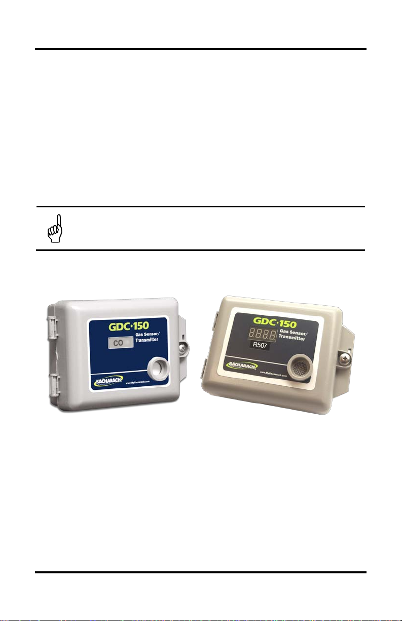
A standard transmitter provides a bi-color LED indicating light for power, fault
condition, and alarm (option with one dry contact relay). An optional LED digital
display is available as well as other enclosure options.
The electrochemical sensor s utilized in this device are acc urate enough to measure to
Occupational Health and Safety hazardous levels for t oxic gases and oxygen levels.
NOTE: The GDC-150 analog transmitters operate by diffusion. If a
sample draw system is desired, consult a Bacharach authorized
distributor or the factory for details.
1.2. Enclosures
Figure 1-1. Standard (NEMA 1X) Enclosures
5209-9000 Rev 0 1
Page 8
GDC-150 Operation Manual
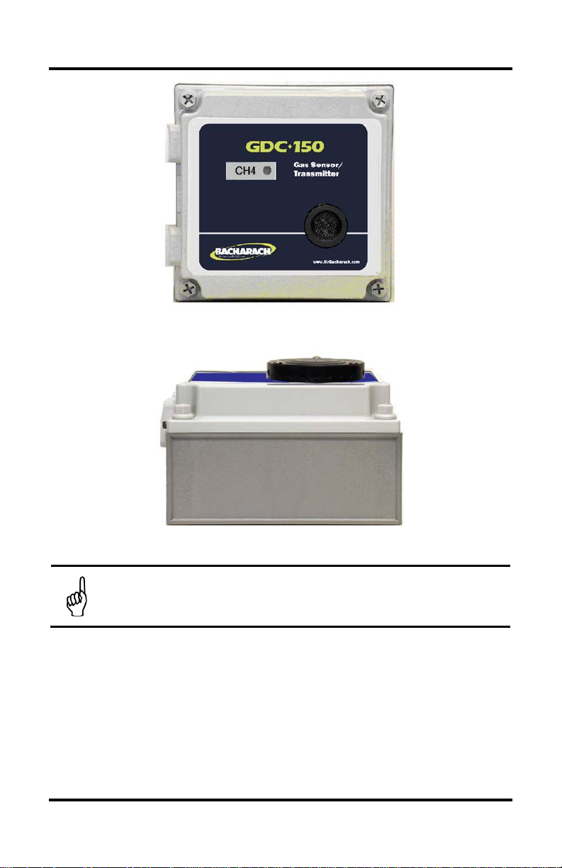
150 transmitters utilizing catalytic combustible or
Figure 1-2. Optional Water-Tight (NEMA 4X) Enclosure
Figure 1-3. Water-Tight Enclosure (Side View) Showing Optional Splash Guard
NOTE: GDC-
electrochemic al H2S/SO2 s ensors are suppli ed with the water - and dusttight NEMA 4X enclosure standard.
2 5209-9000 Rev 0
Page 9
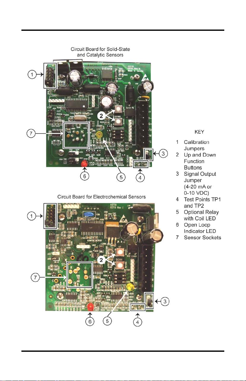
1.3. Key Components
GDC-150 Operation Manual
Figure 1-4. Key Components on GDC-150 Ci rcuit Board
5209-9000 Rev 0 3
Page 10

GDC-150 Operation Manual
Flash Green = Warm-up
Flash Red = Fail
2. SPECIFICATIONS
2.1. General
All Sensor Types
Power 12 VAC to 30 VAC or 16 VDC to 30 VDC
Current
80 to 120 mA
2
1
One bi-color LED:
• Green = Power • Red = Alarm
Indicators
•
One amber LED (int ernal relay coil status indicator)
•
3
One red LED (4-20 mA open-loop indic ator for remote transmitter)
• LED digital display (3.5 digits)
Options
• Relay (one SPDT dry contact relay rated 2A @ 30 VAC)
• Water/dust tight enclosure
• Splash guard (water-tight enc losure only)
2.2. Standard Enclosures
Solid-State Catalytic Electrochemical
Type PVC Polycarbonate PVC
Dims
(HxWxD)
6.5 x 4.4 x 2.5 in
165 x 113 x 65 mm
4.9 x 4.9 x 2.9 in
125 x 125 x 75 mm
6.5 x 4.4 x 2.5 in
165 x 113 x 65 mm
Weight 20 ounces 16 ounces 20 ounces
Construction
2.3. Optional Enclosures
Drip-proof overlap
with hinged door
Solid-State Catalytic Electrochemical
Type Polycarbonate
Dims
(HxWxD)
4.9 x 4.9 x 2.9 in
125 x125 x 75 mm
Weight 16 ounces
Construction
Water- & dust-tight
with hinged door
Water- & dust-tight
with hinged door
Drip proof overlap
with hinged door
Polycarbonate
4.9 x 4.9 x 2.9 in
125 x125 x 75 mm
16 ounces
Water- & dust-tight
with hinged door
1
Non ground referenced supply only
2
For electro-chemical sensors, this depends on the options that are selected.
3
Only supplied if relay option has been selected
4 5209-9000 Rev 0
Page 11

2.4. Sensors (Solid-State and Catalytic)
Type Solid-state MOS
Range
Combustible: 0-50% LEL
Refrigerant: 0-2000 ppm
Solid-State Catalytic
4
Catalytic pellistor
0-100% LEL of target
combustible gas or vapor
Combustible: Approximately 5
to 8 years in clean, ambient
Life Span
conditions
Refrigerant: Approximately 5+
Approximately 5 years in clean,
ambient conditions
years in clean, ambient
1% LEL
-20°C to +40°C
(-4°F to +104°F)
Resolution
Temperature
conditions
Combustible: 1% LEL
Refrigerant: 2 ppm
-20°C to +40°C
(-4°F to +104°F)
Humidity 0-90% non-condensing 0-90% non-condensing
Response
Warm-up
Combustible: T90 = <60 seconds
Refrigerant: T
for most refrigerants
= <120 seconds
90
2 minute delay
24 hours for best performance
(maximum accuracy)
T90 from air to 50% LEL = <12
seconds
2 minute delay
1 hour for best performance
(maximum accuracy)
4
MOS: Metal Oxide Semiconductor
GDC-150 Operation Manual
5209-9000 Rev 0 5
Page 12

GDC-150 Operation Manual
Life
Span
Resolution
Response
Time (T90)
Warm
Up
-40 TO
1
ppm
Hydrogen Sulfide
(H2S)
0-50
ppm
0.5
ppm
-30 to
+50°C
<35 sec
(0-20 ppm)
Nitrogen Dioxide
0-5.0
0.1
-30 to
<60 sec
1-2
ppm
+50°C
(0-50 ppm)
hrs
0-25.0
% vol
0.1%
vol
-30 to
+50°C
<15 sec
(20.9%-0%)
Sulfur Dioxide
(SO2)
0-20
ppm
-30 to
+50°C
<30 sec
(0-20 ppm)
Formaldehyde
0-10
0.2
-20 to
2.5. Sensors (Electrochemical)
Sensor Range
5
Temp RH
6
Ammonia (NH3)
Carbon Monoxide
(CO)
0-500
ppm
0-200
ppm
2
5-8
3
3
3 1 ppm
2
(NO2)
Nitric Oxide (NO)
Oxygen (O2)
ppm
0-100
2 1 ppm
(HCHO)
ppm
2
5
Approximate, in years
6
Non-condensing
7
Temperature drift occurs
8
Without regular calibration
9
Minimum warm-up time
1-2
+50°C715-90% <90 sec
ppm
ppm,
3
8
-20 to
+50°C
10-95% <2 min 1 hr
15-90%
ppm
+50°C
-30 to
15-90%
15-90%
5-95%
15-90%
ppm
+50°C
15-90% <80 sec 1 hr
(0-10 ppm)
<20 sec
2-6
hrs
1 hr
hrs
1-2
1 hr
2 hrs
9
9
9
6 5209-9000 Rev 0
Page 13

GDC-150 Operation Manual
2.6. Sensor Cross Sensitivity (Electrochemical)
Sensor Cross Sensit ivity – Electrochem ical Sensors Only
Ammonia
0-500 ppm
300 ppm CO = 8 10% vol CO2 = -15 35 ppm NO = 6
15 ppm H2S = 30 1 ppm Cl2 = -1 5 ppm HCl = -3
5 ppm SO2 = -0.5 200 ppm H2 = 4 5 ppm NO2 = -1
Carbon
Monoxide
Hydrogen
Sulfide
Conforms to UL 2034 performance specification.
20 ppm SO2 ≤18 50 ppm NO ≤ 6 10 ppm NO2 ≤ -30
10 ppm Cl2 ≤ -25 400 ppm H2 ≤ 1 400 ppm C2H4 ≤ 0.8
400 ppm CO ≤ 4 400 ppm NH3 ≤ 0.1
Nitrogen
Dioxide
50 ppm NO ≤ 0.5 20 ppm SO2 ≤ -2 10 PPM Cl2 = 100
400 ppm H2 ≤ 0.1 20 ppm H2S = -100 400 ppm CO ≤ 0.1
400 ppm C2H4 ≤ 0.1 20 ppm NH3 ≤ 0.1
Nitric Oxide 10 ppm NO2 ≤ 5 20 ppm SO2 ≤ 4 10 ppm Cl2 ≤ 5
400 ppm H2 ≤ 0.1 20 ppm H2S ≤ 60 400 ppm CO ≤ 0.1
20 ppm NH3 ≤ 0.1
Oxygen 5% volume CO2 = 0.1 0% to 95% RH @ 40°C ≤ 0.7
Sulfur Dioxide 50 ppm N O ≤ -3 10 ppm NO2 ≤ -100 10 ppm Cl2 ≤ -70
400 ppm H2 ≤ 0.1 400 ppm CO ≤ 1 400 ppm C2H4 ≤ 40
20 ppm NH3 ≤ 0.1
Formaldehyde
(HCHO)
100 ppm CO <18 100 ppm H2 ≤ 3
Other reducing gases such as alcohol (N ote: Formalin –
commercial gr ade formaldehyde – contains alcohol.)
5209-9000 Rev 0 7
Page 14

GDC-150 Operation Manual
3. INSTALLATION
3.1. Mounting Holes and Conduit Ports
The GDC-150 should be inst alled on a flat vertical s urface with the sensor pointi ng
outwards in a clean, dry environment. If the GDC-150 is to be ins talled in a potentially
wet environment, t he optional water-tight enclosure shoul d have been sel ected. This
reference refers to the standard, general purpose PVC enclosure. Four mounting
holes are provided i n the enclosure bas e for securing the GDC-150 to the wall. Do
not block the front of the encl osure as this is where the sensor is situated and where it
monitors the air for the target gas.
NOTE: Four mounting holes are provided in the enclosure base for
securing the GDC-150 to the w all. The mounting holes ar e 3/16″ (4.8
mm) in diameter.
Conduit entry points are provided for the PVC enclosure.
Figure 3-1. Standard Enclosure Showi ng Mounting Holes
The water-tight enclosure mus t be ins t all ed wi th t he mount ing s c r ews pass i ng thr ough
the same openings t hat accommodate the four door securing screws . This ensures
the mounting screws are outside of the door gasket and confirms a water-tight
installation.
NOTE: No conduit entry points are provided for the water-tight
enclosure. The reason is the installer may not want one where we
would place it and this would result in unnecessary openin gs into this
enclosure.
8 5209-9000 Rev 0
Page 15

GDC-150 Operation Manual
Figure 3-2. Water-Tight Enclosure Showing Mounting Holes
WARNING: Do not dril l holes in the back of the bas e of the enclosure
for the purpose of mounting the sensor/transmitter. Leak paths can
occur. Corr osion damage will not be covered under warrant y.
NOTE: Use caution when drilli ng holes in the water-tight enclos ure for
conduit entry so as not to damage the circuit board inside. Use liquid
tight conduit hubs wherever conduit enters the water-tight enclosure.
Failure to do so cr eates a leak path. Water r unning down the conduit
enters the inter ior of the enclosure and c ould corrode the c ircuit board.
This is not covered under warranty.
NOTE: When mounting either enclosure, allow enough room to enable
the end user to open the door fully to acc ess the internal adjustments.
3.2. Enclosure Door
The standard enclosure has one s crew securing the door to the base for electr ical
safety and provid es an opening to al low the user to ap ply a zip ti e if they desire t he
transmitter to be locked more securely. Refer to Figure 1-1 on page 1.
The door of the standard enclosure c an be easily removed to fac ilitate instal lation of
the base. Simply grasp t he lid with one hand, being careful not to make cont act with
any of the intern al components (circuit board) , and grasp the bas e with your other
hand. Tug on the base, pulling i t towards you. The section of the hinges located on
the base should “snap” apart from the part of the hinges locat ed on the door.
5209-9000 Rev 0 9
Page 16

GDC-150 Operation Manual
After instal lation, simply l ocate the lid hinges over the inst alled base hinges and pull
toward you. The hinges should easily “snap” back into place.
By design, the overlapping d oor of the PVC enclosure makes i t inherently drip proof,
although it is not water ti ght or dust t ight. The opti onal water-t ight encl osure has four
screws for sealing the door to the base. Refer to Figure 1-2 on page 2.
3.3. Sensor Mounting Height Recommendations
Some toxic gases such as ammoni a (NH
) are light er than air, therefore the sensor/ transmitter should be installed on or
(CH
4
near the ceiling.
Some toxic gases s uc h as carbon monoxide are o nly s l ight ly l i ghter than ai r , t her efor e
the sensor/transmitter should be i nstalled at approximately 4’ to 6’ from t he floor.
Oxygen sensors should be installed at approximately 4’ to 6’ from the floor.
For toxic gases, combustible gases, and vapors that are heavier than air, the
sensor/transmitter should be inst alled with the sensor opening at 6” from the f loor.
Although most r efrigerant s (e. g., Freons) are hea vier than ai r, some applicat ions may
be better suited t o a slightly higher mount ing height for ref rigerant sensors.
NOTE: If the area to be monitored is a wet environment, water-tight
enclosures shoul d be used. Th e water -ti ght encl osure m ust be ins tall ed
using the indic ated holes or it may leak. Damage c aused by leaking
because of improperly installed enclosures is not covered under
warranty. If the area to be monitored has the potential for water spray, a
splash guard should be used to protect the sensor.
3.4. Wiring the GDC-150 for Power
If powering the GDC-150 with 24 VAC, use terminals 1 and 2. If powering the
GDC-150 wit h 24 VDC, the posi tive (r ed) wire should be c onnected to ter minal 2 and
the negative (bl ack) wire shoul d be connected to term inal 3. The signal wire is always
connected to termi nal 4. See Figure 3-4 for proper wiring examples and Figure 3-5
for improper wi ring examples.
Terminals 5, 6, and 7 are used only if the relay option has been supplied. Double
check the relay r atings in the s pecifications section of this m anual before oper ation.
For normal operatio n, the relay contr ol wiring should be connec ted to N/C and COM
(fail-safe operation is used).
) an d combusti ble gases suc h as methane
3
10 5209-9000 Rev 0
Page 17

GDC-150 Operation Manual
Figure 3-3. Power and Optional Rela y Wiring
NOTE: The m ain wiri ng terminal strip on t he GDC-150 circ uit board can
be unplugged for eas ier wiring inst allation. Grasp the two s ides of the
terminal stri p and lift upward with a sl ight side to side rock ing motion.
NOTE: DO NOT use solid-core wire for connection to wiring terminal
strip. Any damag e caused by using sol id-core wire will voi d warranty.
Use stranded wire ONLY.
IMPORTANT: The GDC-150 is a low voltage powered device. Any
application of operating voltages higher than indicated in the manual
may result in damage. Double check wiring connections prior to
powering the trans mitter. Damage f rom incorrec t wiring conne ctions or
from too much volt age are not covered under w arranty.
IMPORTANT: When providing power to the GDC-150, use nongrounded referenc e suppl ies onl y. Refer to Figure 3-4 for prope r wiri ng
examples and Figure 3-5 for improper wiring examples.
5209-9000 Rev 0 11
Page 18

GDC-150 Operation Manual
Figure 3-4. Proper Wiring Examples
12 5209-9000 Rev 0
Page 19

Figure 3-4. Proper Wiring Exampl es ( Continued)
Figure 3-5. Improper Wiring Example
4. OPERATION
4.1. General
After installation, double check wiring prior to applying power to the GDC-150
transmitter. Remember, these are low voltage devices. Af ter power up, the outer
LED will flash gr een indicating the sys tem is in a warm -up period. During the warm up period, the si gnal o ut put f r om the GDC-150 is fixed at 4.0 m A . If the di gi tal dis pl ay
option has been fitted, t he LED displ ay will indic ate a scroll ing decimal “…..” unti l the
warm-up is completed. If the relay option has been s elected, the relay is not activat ed
during warm-up. The GDC-150 has been programmed with a 5-minute warm-up
period. After the warm-up is compl eted, the signal output and digital display (i f this
option has been supplied) will indicate current gas readings (if any).
If the relay option has been sup plied, i t will have a factor y preset al arm set poi nt (this
can easily be changed in the field). In a non-alarm state, the outer LED will be
illuminated green and the amber relay coil inner LED will be illuminated. The
illuminated relay coil LED indicat es to the user that the relay coil i s energized. The
relay option on the GDC-150 has been designed to operate in a fail-safe manner,
meaning that the rel ay c oil is energized in non-gas-alarm stat e and de-ener gize whe n
a gas alarm is indi cated. The devi ce t o be contr olled s hould be connec ted to t he N/C
(normally closed) and COM (common) terminals. In the event of a sensor failure,
anything control led by the relay is activated continuously until the fail condit ion has
been corrected.
5209-9000 Rev 0 13
GDC-150 Operation Manual
Page 20

GDC-150 Operation Manual
4.2. Detecting Gas
Upon detecti on of the presence of target gas, t he signal output increases t o a value
equal to the amo unt of gas being d etected by the s ensor. If the LED display option
has been supplied, t his value wil l be displayed. If the c oncentration of gas is above
the preset alarm threshold, the outer LED changes to red, the alarm relay deenergizes and the am ber relay coil LED goes out.
As the detected gas l evel subsides, t he output signal will dec rease again to a value
equal to anythin g being det ected by the sensor an d this wi ll be indic ated on th e LED
display (if this option has been selected). T he relay will aut omaticall y reset after the
signal drops below the set point value.
4.3. System Failure
In the event of a system failure, the outer LED will flash red, the r elay will de-energize,
the relay coil LED will go out an d the output signal wi ll drop bel ow 4.0 mA . A failure
can consist of a burned out sensor element (solid-state or catalytic), a failed or
damaged component on the circuit board, or a wiring-relat ed problem.
4.4. Sensor Notes
Sensor Type
Solid-State
(Refrigerant)
Solid-State
(Combustible)
Catalytic
(Combustible)
Electrochemical
(E.g., Oxygen)
10
Sensors require lengthy warm up and stabilization time after installation. Do not
perform any calibration functions until the sensors have been operating for at least 24
hours.
10
Operation Notes
• Not gas specific
• Respond to a fairly wide range of interfering gases and
vapors
• Temperature and humidity compensated to reduce drif t in
environments wher e these values c hange regularly
• Not gas specific, but are less likely to suffer from false
alarms from interfering gases (due to the extremely high
measuring range for which they have been calibrated)
• Specific to combustible gases and vapors
• Temperature compensated
• These sensors are qui te gas specific
• Will respond to some other gases (s ee cross sensitive
gases table on page 7 for more informati on)
• Temperature compensation to reduce drift in environments
where the temperat ure changes regularly
14 5209-9000 Rev 0
Page 21

GDC-150 Operation Manual
4.5. Open Loop Diagnostic
The GDC-150 circuit board h as been fitted with a r ed LED located near t he bottom
center of the c i rc ui t boar d. Thi s is an “ open l oop” in dic at or and h as been des ign ed as
a quick trouble shooting device. If the 4-20 m A signal loop has not been c onnected
properly or has be en damaged in s ome manner between t he analog trans mitter and
the device to which i t is sending its signal output , this LED il luminates. At this point,
the wiring should be i nspected for potential problems.
4.6. Jumper Functions
Figure 4-1. Jumper Functions
4.7. Adjusting the Alarm Set Point (For Relay Option Only)
If the optional r elay has been s upplied, the alar m set point on the GDC-150 can be
adjusted. The alarm set point value is converted to a voltage in the range of 0-4 VDC.
This voltage range correlates to the full measurement range of the installed sensor.
4.7.1. Calculating the Alarm Set Point Value
Prior to adjusting t he alarm set point, calc ulate the voltage value required using the
following formul a.
Example: Catalytic combustible sensors have a standard measurement range of
0-100% LEL. Therefore 4.0 VDC = 100% LEL. Using the values below, 10% of
4.0 VDC = 0.4 VDC. Therefore, the required volt age setting to ac hieve an alarm s et
point of 10% LEL is 0.4 VDC.
5209-9000 Rev 0 15
Page 22

GDC-150 Operation Manual
Figure 4-2. Calculating the Alarm Set Point
4.7.2. Adjusting the Alarm Set Point
Step Description
Move the jumper t o position P5. The green outer LED will flash onc e
1.
within 2 seconds for confir mation. The system is now wait i ng fo r the us er
to set the desired value.
Attach volt met er leads to test points TP1 and TP2 (see Figure 1-4 on
2.
page 3). Alt ernativel y, if the op tional LED digital di splay has been fi tted,
read the value indic ated on the display.
Use the UP or DOWN push buttons until the calculated voltage is
3.
displayed on the volt m eter (or on the optional LED digital display).
Move the jumper bac k to its resting posit ion (P1). At this time the new
4.
value is saved and the green LED flashes once for confirmation.
5. CALIBRATION
5.1. Frequency Recommendatio ns
Sensor Types / Applications Calibration Frequency
Parking garage detectors Once every 12 months
OHS (Occupational Health and Safety) appl ications Once every 6 months
For the purposes of safety in O HS applicati ons, sensor s should be gas t ested (bump
tested) once every m onth to confirm response.
Required Equipment :
• Vol t meter
• Calibration kit
• Calibration gases.
Users can order the calibration kit, calibration accessories and/or gases from any
Bacharach authorized distribut or or they can suppl y their own gas and eq uipment as
long as the gas meets the minimum specifications indicated in this manual.
16 5209-9000 Rev 0
Page 23

GDC-150 Operation Manual
NOTE: It is recommended that a c alibration label should be applied after
every calibration to confirm work performed and the date it was
confirmed. If a controller is involved, the alarm set points should be
indicated on a label on the front door of the enclosure so anyone
working in the envir onment will be aware.
NOTE: For best performance and to ensure the sensor meets the
indicated specifications, all electrochemical sensors should be calibrated
every six months. The sensors may not perform to the listed
specificati ons if they are not maintai ned regularly.
5.2. Calibration Specifications – Gases
Calibration span gases should be at least ±5% accuracy and have a current date
stamp. Gas generator s s hould hav e a cur rent dat ed cel l ins talled. Ser vic e pers onnel
should flow zero emissions air or oxygen bef ore attempting to null adjust toxic gas
sensors.
NOTE: For most electrolytic sensors, nitrogen (N
for zero air. However, f or solid-state and catal yti c sens ors, nitr ogen ( N
should not be substituted for zero air because all solid-state and
catalytic s ensors requir e at least a small volume of Oxygen to operat e.
Calibration wil l be inaccurate.
5.3. Regulators and Flow – Solid-State and Catalytic Sensors
Calibration gases that ar e li ghte r than or t he s ame wei ght as air ( CH4, H2, etc.) should
be flowed at 0.5 LPM . Gases h eavier tha n air (C
, etc.) should be f lowed between
3H8
0.5 and 1.0 LPM. Fixed flow r egulators provide more accur acy. Gases should be
flowed over the sensor for at least 3 minutes.
The proper calibr ation adapter should be util ized to allow the gas to proper ly diffuse
around the sensor . They are available from Bacharach (see table on page 21).
A humidification chamber must be utilized for all solid-state sensors. This is also
available from Bacharach (see table on page 21).
5.4. Regulators and Flow – Electrochemical Sensors
Calibration gases should be flowed at 0. 5 LPM. Fixed flow regul ators provide more
accuracy. Zero air and span gases should be flowed over the sensor for at least
3 minutes.
The proper calibr ation adapter should be util ized to allow the gas to proper ly diffuse
around the sensor . They are available from Bacharach (see tabl e on page 21).
For best perform ance an d to ensur e the s ensor m eets t he indicated specific ations , all
electrochemical sensors s hould be calibrated every six months. The sensors may n ot
perform to the li sted specificati ons if they are not maintained regularly.
5209-9000 Rev 0 17
) can be substituted
2
)
2
Page 24

GDC-150 Operation Manual
line between the cylinder of span gas and the calibration adapter.
he chamber and wet it under the tap.
5.5. Calculating the Span Gas Value
To achieve calibr at ion t he user m ust f irst tel l the GD C-150 w hat c onc entr ati on of span
he is going to fl ow over the sensor . Within the transmitter, this is a voltage s etting.
The range of 0-4 VDC is equal to the full meas urement range of the sensor . Pri or t o
attempting to calibrate, determine the voltage value required.
Use the following formula to calculat e the voltage required.
Therefore, in this example, the required voltage setting to calibrate a 0-2000 ppm
sensor with 1000 ppm is 2.0 VDC.
NOTE: When calibrating solid-state sensors for combustibles or
refrigerants, the span gas must be humidified. The use of a
humidificati on chamber is required. The h umidification cham ber sits in
Remove the sponge inside t
Squeeze out the e xcess w ater s o it i s not dr ipping w et and pl ace i t back
inside the chamber. As gas flows through the chamber, it absorbs wat er
which acts to humidify it and the humidified span gas flows over the
sensor. See page
NOTE: Values for
21 for ordering information.
Calibration Span Gas and Sensor Range in the
above equations mus t have the same Engineer ing Units (e.g. , PPM, %
of LEL, % vol, etc.).
18 5209-9000 Rev 0
Page 25

GDC-150 Operation Manual
5.6. Setting the Span Gas Value
Step Setting the Span Gas Value Procedure
Move the jump er to positi on P2 (see Figure 4-1 on page 15). The green
1
outer LED flashes once for conf irmation. The syst em is now waiting f or
the user to set the desired value.
Attach volt met er leads to test points TP1 and TP2 (see Figure 1-4 on
2
page 3). Alt ernativel y, if the op tional LED digital di splay has been fi tted,
read the value indic ated on the display.
Use t he UP or DOWN push-buttons (see Figure 1-4 on page 3) until the
3
calculated voltage is displayed on the volt meter (or the optional LED
digital display).
Move the jumper bac k to its resting posit ion (P1). At this time the new
4
value is saved and the green LED flashes once for confirmation.
5.7. Calibrating the Null (Zero) Value
Step Calibrating the Null ( Zero) Value Procedure
1 Attach a regulator to a cylinder of zer o air (or nitrogen).
Insert the cal ibration adapter in to the sensor opening i n the front of the
enclosure door. Use a slight twisting motion as you gently push the
calibration ada pter into the sensor opening. If the calibr ation adapter is
hard to insert, moisten the "O" ring s lightly then try r e-inserting it. If the
2
transmitter has been fitted with an optional splash guard, remove the
plastic plug from the center of the splash guard to gain access to the
sensor opening. To r emo ve th e plas t ic pl ug, pus h inw ard at th e center of
the plug until the edg es l ift slightl y then s lip a smal l fl at blade scr ewdri ver
under and pop the plug off.
3 Open the regulator valve fully and allow zero air to flow over sensor.
Move the jumper t o position P3 (see Figure 4-1 on page 15). The outer
4
LED will change to a steady amber color. The system now waits 30
seconds to ensur e the user is flowing zero air.
The GDC-150 then enters a c ount down duri ng which tim e it adjusts t he
null value. The length of this count down period is:
• 90 seconds for catalytic and solid-stat e sensors
5
6 Move the jumper back t o its resting posit ion (P1) and remove the zero air.
5209-9000 Rev 0 19
• 60 seconds for electrochemical sensors.
If desired, attach the volt meter leads to test points TP1 and TP2 (see
Figure 1-4 on page 3). The meter will show 0.0 VDC, climb t o a higher
value, th en slowly descend back t o 0.0 VDC indicati ng the GDC-150 has
null adjusted the c ircuit. Onc e the count down is fi nished, the outer LED
changes back to gr een indicating the proc edure is complete.
Page 26

GDC-150 Operation Manual
IMPORTANT: If the user attempts to null adjust the sensor without
applying zero air and the sensor detects background gas the amber
LED flashes to advise the user that it is out of tolerance.
5.8. Calibrating the Span Value
Step Calibrating the Span Value Procedure
1 Attach regulator to cylinder of span gas.
Insert the cal ibration adapter in to the sensor opening i n the front of the
enclosure door. Use a slight twisting motion as you gently push the
2
calibration ada pter into the sensor opening. If the calibrati on adapter is
hard to insert, m oisten the “o” ring seal slightly then try re-inserting it.
3 Open regulator valv e fully and allow span gas to flow over sensor.
Move the jumper to J4 positi on (see Figure 4-1 on p age 15). The tri-color
4
outer LED will change to a stead y am ber color. The system now waits 30
seconds to ensur e the user is flowing span gas.
The GDC-150 then ent ers a count down (180 s econds for catalytic and
solid-state sensors, 150 seconds for Electrochemical sensors) during
which time it adjusts the circuit to the span value whi ch was set earlier
(see “Setting t he Span Gas Value”).
If the user wishes to view this, att ach meter leads to test poi nts TP1 and
5
TP2 (see Figure 1-4 on page 3). The meter will show an increasing
voltage indicat ing t he GDC-150 sensor is r espondin g t o the s pan gas and
the circuit is being adjusted for accuracy. Alternatively, If the optional
LED digital dis play has been f itted, r ead the valu e indicated on the out er
digital display. Onc e the count down is finished, t he outer LED chang es
back to green indicating the procedure is complete.
Before removing the span gas, move the jumper back to its resting
6
position (J1) and the new value is saved.
IMPORTANT: If the user attempts to span adjust the sensor without
applying span gas or the proper value of span gas, the sensor will
produce a respo nse that i s outside of the cir cuit pres et toleranc e value.
The amber LED flashes to advise the user that it is out of toler ance.
20 5209-9000 Rev 0
Page 27

6.1. Metal Protective Guards
6. ACCESSORIES AND REPLACEMENT PARTS
GDC-150 series analog transmitters are all
supplied in very rugged, non-metallic
enclosures. However, in some applications
more protection may be desired. Bacharach
can provide protective guards made from 16
gauge galvanized metal with a pattern of
square perforations to permit air and gas to
diffuse easil y to the sensor.
6.2. Accessory and Replacement Part Numbers
Part
Number
5209-0002 LED digital display (must be select ed w hen ordering)
5209-0003 Relay (rated 2A @ 30 VAC)
5209-0005 Water- and dust-tight NEMA 4X enclosure
5209-0004 Splash guard (NEMA 4X enclosure only)
5209-0006 Calibration adapter for all other sensors
5209-0016 Calibration adapter for catalytic sensors
5209-0017 Sample draw pump (24 VAC-powered)
5209-0018 Sample draw pump (24 VDC-powered)
5209-0019 Transmitter guard (16 gauge galvanized metal)
5209-0021 Humidification chamber (for calibration of solid-state sens ors)
5209-9000 Rev 0 21
GDC-150 Operation Manual
Figure 6-1. Protective Gu ard
Description
∇ ∇ ∇
Page 28

GDC-150 Operation Manual
World Headquarters
621 Hunt Valley Circle, New Kensington, Pennsylvania 15068
Phone: 724-334-5000 • Toll Free: 1-800-736-4666 • Fax: 724-334-5001
Website: www.MyBacharach.com • E-mail: help@MyBacharach.com
22 5209-9000 Rev 0
 Loading...