

Page 1

AXIST99A12PositioningUnit24VAC/DC
InstallationGuide
Page 2

Page 3

English
EN
Français
Deutsch
Italiano
Español
日本語
中文:简体中文
FR
DE
IT
ES
JA
ZH
Page 4

Readthisrst
ReadthroughthisInstallationGuidecarefullybefore
installingtheproduct.KeeptheInstallationGuidefor
futurereference.
Legalconsiderations
Videoandaudiosurveillancecanberegulatedbylaws
thatvaryfromcountrytocountry.Checkthelaws
inyourlocalregionbeforeusingthisproductfor
surveillancepurposes.
Liability
Everycarehasbeentakeninthepreparationofthis
document.PleaseinformyourlocalAxisofceof
anyinaccuraciesoromissions.AxisCommunications
ABcannotbeheldresponsibleforanytechnicalor
typographicalerrorsandreservestherighttomake
changestotheproductandmanualswithoutprior
notice.AxisCommunicationsABmakesnowarranty
ofanykindwithregardtothematerialcontained
withinthisdocument,including,butnotlimitedto,
theimpliedwarrantiesofmerchantabilityandtness
foraparticularpurpose.AxisCommunicationsAB
shallnotbeliablenorresponsibleforincidental
orconsequentialdamagesinconnectionwiththe
furnishing,performanceoruseofthismaterial.This
productisonlytobeusedforitsintendedpurpose.
Intellectualpropertyrights
AxisABhasintellectualpropertyrightsrelatingto
technologyembodiedintheproductdescribedinthis
document.Inparticular,andwithoutlimitation,these
intellectualpropertyrightsmayincludeoneormoreof
thepatentslistedataxis.com/patentandoneormore
additionalpatentsorpendingpatentapplicationsin
theUSandothercountries.
Equipmentmodications
Thisequipmentmustbeinstalledandusedin
strictaccordancewiththeinstructionsgivenin
theuserdocumentation.Thisequipmentcontains
nouser-serviceablecomponents.Unauthorized
equipmentchangesormodicationswillinvalidateall
applicableregulatorycerticationsandapprovals.
Trademarkacknowledgements
AXISCOMMUNICATIONS,AXIS,ARTPECandVAPIX
areregisteredtrademarksofAxisABinvarious
jurisdictions.Allothertrademarksaretheproperty
oftheirrespectiveowners.
Regulatoryinformation
Europe
ThisproductcomplieswiththeapplicableCEmarking
directivesandharmonizedstandards:
•ElectromagneticCompatibility(EMC)Directive
2014/30/EU.SeeElectromagneticcompatibility
(EMC)onpage4.
•LowVoltageDirective(LVD)2014/35/EU.See
Safetyonpage5.
•RestrictionofHazardousSubstances(RoHS)
Directive2011/65/EUand2015/863,including
anyamendments,updatesorreplacements.See
Disposalandrecyclingonpage5.
Acopyoftheoriginaldeclarationofconformity
maybeobtainedfromAxisCommunicationsAB.See
Contactinformationonpage5.
Electromagneticcompatibility(EMC)
Thisequipmenthasbeendesignedandtestedtofulll
applicablestandardsfor:
•Radiofrequencyemissionwheninstalled
accordingtotheinstructionsandusedinits
intendedenvironment.
•Immunitytoelectricalandelectromagnetic
phenomenawheninstalledaccordingtothe
instructionsandusedinitsintendedenvironment.
USA
Thisdevicecomplieswithpart15oftheFCCRules.
Operationissubjecttothefollowingtwoconditions:
1.Thisdevicemaynotcauseharmfulinterference,
and
2.thisdevicemustacceptanyinterferencereceived,
includinginterferencethatmaycauseundesired
operation.
Thisequipmenthasbeentestedusingashielded
networkcable(STP)andfoundtocomplywiththe
limitsforaClassAdigitaldevice,pursuanttopart15
oftheFCCRules.Theselimitsaredesignedtoprovide
reasonableprotectionagainstharmfulinterference
whentheequipmentisoperatedinacommercial
environment.Thisequipmentgenerates,uses,andcan
radiateradiofrequencyenergyand,ifnotinstalledand
usedinaccordancewiththeinstructionmanual,may
causeharmfulinterferencetoradiocommunications.
Operationofthisequipmentinaresidentialareais
likelytocauseharmfulinterferenceinwhichcasethe
userwillberequiredtocorrecttheinterferenceathis
ownexpense.Theproductshallbeconnectedusinga
shieldednetworkcable(STP)thatisproperlygrounded.
Contactinformation
AxisCommunicationsInc.
300ApolloDrive
Chelmsford,MA01824
UnitedStatesofAmerica
Tel:+19786142000
Canada
Thisdigitalapparatuscomplieswith
CANICES-3(ClassA).Theproductshallbe
connectedusingashieldednetworkcable(STP)that
isproperlygrounded.Cetappareilnumériqueest
conformeàlanormeCANNMB-3(classeA).Leproduit
doitêtreconnectéàl'aided'uncâbleréseaublindé
(STP)quiestcorrectementmisàlaterre.
Europe
ThisdigitalequipmentfulllstherequirementsforRF
emissionaccordingtotheClassAlimitofEN55032.
Theproductshallbeconnectedusingashielded
networkcable(STP)thatisproperlygrounded.Notice!
ThisisaClassAproduct.Inadomesticenvironment
thisproductmaycauseRFinterference,inwhichcase
theusermayberequiredtotakeadequatemeasures.
Australia/NewZealand
Thisdigitalequipmentfulllstherequirements
forRFemissionaccordingtotheClassAlimitof
AS/NZSCISPR32.Theproductshallbeconnected
usingashieldednetworkcable(STP)thatisproperly
grounded.Notice!ThisisaClassAproduct.Ina
domesticenvironmentthisproductmaycauseRF
interference,inwhichcasetheusermayberequired
totakeadequatemeasures.
Japan
Page 5
この装置は、クラスA機器です。この装置を
住宅環境で使⽤すると電波妨害を引き起こす
ことがあります。この場合には使⽤者が適切
な対策を講ずるよう要求されることがありま
す。VCCI‒A
本製品は、シールドネットワークケーブル
(STP)を使⽤して接続してください。また適切
に接地してください。
本製品は電気通信事業者(移動通信会社、固
定通信会社、インターネットプロバイダ等)
の通信回線(公衆無線LANを含む)に直接接
続することができません。本製品をインター
ネットに接続する場合は、必ずルータ等を経
由し接続してください。
Korea
이기기는업무용환경에서사용할목적으로적
합성평가를받은기기로서가정용환경에서사
용하는경우전파간섭의우려가있습니다.적절
히접지된STP(shieldedtwistedpair)케이블을
사용하여제품을연결하십시오.
Safety
ThisproductcomplieswithIEC/EN/UL62368-1,
safetyofaudio/videoandITequipmentand
IEC/EN/UL60950-22,SafetyofInformation
TechnologyEquipment.Theproductshallbegrounded
usingboththeprotectiveearthwireinthepower
cableandthegroundingbraid.Makesurebothendsof
theprotectiveearthwireandthegroundingbraidare
incontactwiththeirrespectivegroundingsurfaces.
Thepowersupplyusedwiththisproductshallhave
aratedoutputvoltagewithinvoltagerangeof
20-28VAC/DC,andamaxcurrentratingof10.5A.
Thepowersupplyusedwiththisproductshallfulll
oneofthefollowingrequirements:
•SafetyExtraLowVoltage(SELV)accordingto
clause2.2ofIEC/EN/UL60950-1
•Class1electricalenergysource(ES1)according
toIEC/EN/UL62368-1
WerecommendtheuseofAxispowersupplyDINPS24
480W.
Disposalandrecycling
Whenthisproducthasreachedtheendofits
usefullife,disposeofitaccordingtolocallawsand
regulations.Forinformationaboutyournearest
designatedcollectionpoint,contactyourlocal
authorityresponsibleforwastedisposal.Inaccordance
withlocallegislation,penaltiesmaybeapplicablefor
incorrectdisposalofthiswaste.
Europe
Thissymbolmeansthattheproductshallnotbe
disposedoftogetherwithhouseholdorcommercial
waste.Directive2012/19/EUonwasteelectrical
andelectronicequipment(WEEE)isapplicablein
theEuropeanUnionmemberstates.Toprevent
potentialharmtohumanhealthandtheenvironment,
theproductmustbedisposedofinanapproved
andenvironmentallysaferecyclingprocess.For
informationaboutyournearestdesignatedcollection
point,contactyourlocalauthorityresponsiblefor
wastedisposal.Businessesshouldcontacttheproduct
supplierforinformationabouthowtodisposeofthis
productcorrectly.
Thisproductcomplieswiththerequirementsof
Directive201 1/65/EUand2015/863ontherestriction
oftheuseofcertainhazardoussubstancesinelectrical
andelectronicequipment(RoHS).
China
Thisproductcomplieswiththerequirements
ofSJ/T1 1364-2014,Markingfortherestrictionof
hazardoussubstancesinelectricalandelectronic
products.
有毒有害物质或元素
部
件
名
称
电
气
实
装
部
分
0:表示该有毒有害物质在该部件均质材料
中的含量均在GB/T26572标准规定的限量要
求以下。
X:表示该有毒有害物质至少在该部件的某一
均质材料中的含量超出GB/T26572标准规定的
限量要求。
汞
铅
(Hg)
(Pb)
00000
X
六
镉
价
(Cd)
铬
(Cr(VI))
多
多
溴
溴
二
联
苯
苯
醚
(PB-
(PB-
B)
DE)
Contactinformation
AxisCommunicationsAB
Gränden1
22369Lund
Sweden
Tel:+46462721800
Fax:+4646136130
axis.com
Warrantyinformation
ForinformationaboutAxis’productwarrantyand
theretorelatedinformation,gotoaxis.com/warranty.
Support
Shouldyourequireanytechnicalassistance,please
contactyourAxisreseller.Ifyourquestionscannotbe
answeredimmediately,yourresellerwillforwardyour
queriesthroughtheappropriatechannelstoensurea
rapidresponse.IfyouareconnectedtotheInternet,
youcan:
•ndanswerstoresolvedproblemsintheFAQ
database,searchbyproduct,category,orphrase
•reportproblemstoAxissupportstaffbylogging
intoyourprivatesupportarea
•chatwithAxissupportstaff
•visitAxisSupportataxis.com/support
Learnmore!
VisitAxislearningcenteraxis.com/learningforuseful
trainings,webinars,tutorialsandguides.
Page 6

Page 7

AXIST99A12PositioningUnit24VAC/DC
Safetyinformation
Hazardlevels
DANGER
Indicatesahazardoussituationwhich,ifnotavoided,willresultindeathorseriousinjury.
WARNING
Indicatesahazardoussituationwhich,ifnotavoided,couldresultindeathorseriousinjury.
CAUTION
Indicatesahazardoussituationwhich,ifnotavoided,couldresultinminorormoderate
injury.
NO
TICE
NO NO
TICE TICE
Indicatesasituationwhich,ifnotavoided,couldresultindamagetoproperty.
Othermessagelevels
Important
Indicatessignicantinformationwhichisessentialfortheproducttofunctioncorrectly.
Note
Indicatesusefulinformationwhichhelpsingettingthemostoutoftheproduct.
Safetyinstructions
DANGER
Riskofelectricshock.Allcablesshallbede-energizedbeforeinstallingorperforming
maintenanceontheproduct.
CAUTION
Movingparts.Riskofinjury.Keepyourbodypartsawayfromtheproductwhenit's
inoperation.Disconnectfrompowersupplybeforeinstallingorperformingmaintenance
ontheproduct.
CAUTION
Hotsurface.Riskofinjury.Don'ttouchtheproductwhenit'sinoperation.Disconnect
frompowersupplyandallowthesurfacestocoolbeforeperformingmaintenanceon
theproduct.
NO
TICE
NO NO
TICE TICE
•TheAxisproductshallbeusedincompliancewithlocallawsandregulations.
•StoretheAxisproductinadryandventilatedenvironment.
•AvoidexposingtheAxisproducttoshocksorheavypressure.
•Donotinstalltheproductonunstablepoles,brackets,surfacesorwalls.
EN
7
Page 8

AXIST99A12PositioningUnit24VAC/DC
•UseonlyapplicabletoolswheninstallingtheAxisproduct.Usingexcessiveforcewith
powertoolscouldcausedamagetotheproduct.
•Donotusechemicals,causticagents,oraerosolcleaners.
•Useacleanclothdampenedwithpurewaterforcleaning.
•Useonlyaccessoriesthatcomplywiththetechnicalspecicationofyourproduct.These
canbeprovidedbyAxisorathirdparty.AxisrecommendsusingAxispowersource
equipmentcompatiblewithyourproduct.
•UseonlysparepartsprovidedbyorrecommendedbyAxis.
•Donotattempttorepairtheproductyourself.ContactAxissupportoryourAxisreseller
forservicematters.
•Useayellow/greencoloredgroundingcableofatleast0.5mm
Transportation
NO
TICE
NO NO
TICE TICE
•WhentransportingtheAxisproduct,usetheoriginalpackagingorequivalenttoprevent
damagetotheproduct.
2
or20AWG.
8
Page 9

Packagecontents
•Positioningunit
•Powerconnector
•I/Oconnector
•Torx®bitT20(long)andT30
AXIST99A12PositioningUnit24VAC/DC
EN
9
Page 10
AXIST99A12PositioningUnit24VAC/DC
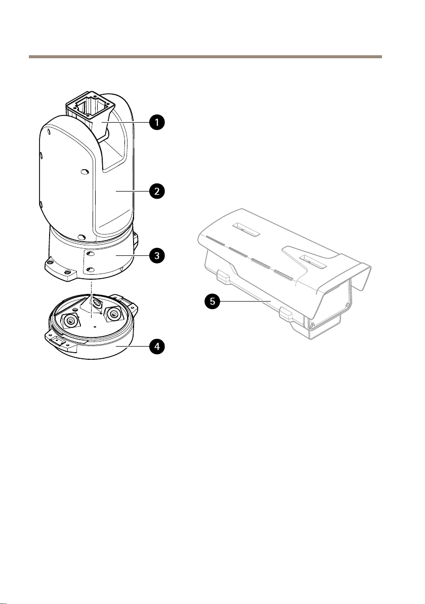
Productoverview
1
2
3
4
5
Positioningunit(tilt)
Positioningunit(pan)
Lid
Baseunit
Camera(notincluded)
10
Page 11
AXIST99A12PositioningUnit24VAC/DC
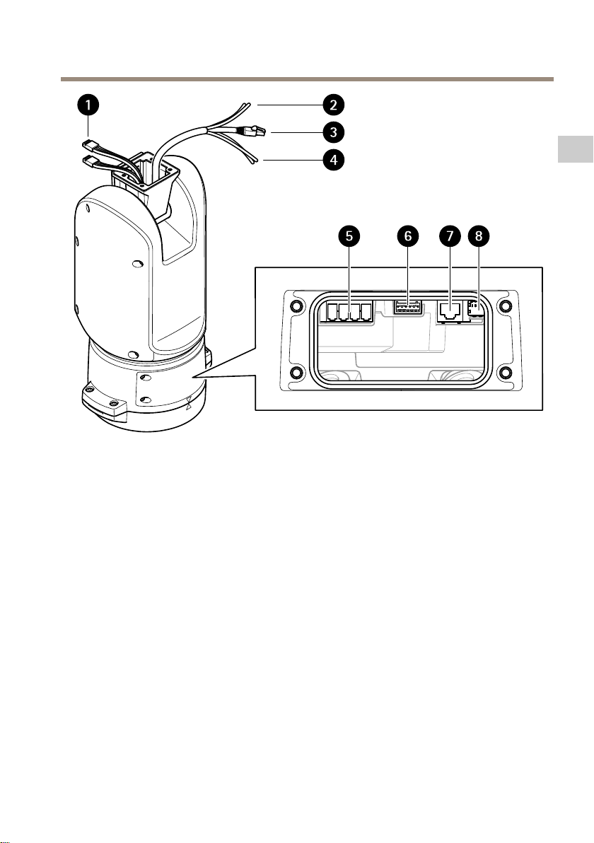
1
Illuminatorcables(nottobeused)
2
Camerapowercable
3
Cameranetworkcable
4
Cameraserialinterfacecable
5
Inputpowerconnector
6
I/Oconnector
7
RJ45connector
8
SFPslotforSFPmodule(SFPmodulenotincluded)
EN
11
Page 12
AXIST99A12PositioningUnit24VAC/DC
Howtoinstalltheproduct
DANGER
Riskofelectricshock.Allcablesshallbede-energizedbeforeinstallingtheproduct.
CAUTION
Theelectricalconnectionsandconduitinstallationsshallbemadebyacertiedelectrician
andincompliancewithlocalregulations.
CAUTION
Riskofinjury.Movingparts.Keepyourbodypartsawayfromtheproductwhenin
operation.Disconnectfrompowersupplybeforeinstallingorperformingmaintenance
ontheproduct.
CAUTION
Riskofinjury.Hotsurface.Donottouchtheproductwheninoperation.Disconnect
frompowersupplyandallowthesurfacestocoolbeforeperformingmaintenanceon
theproduct.
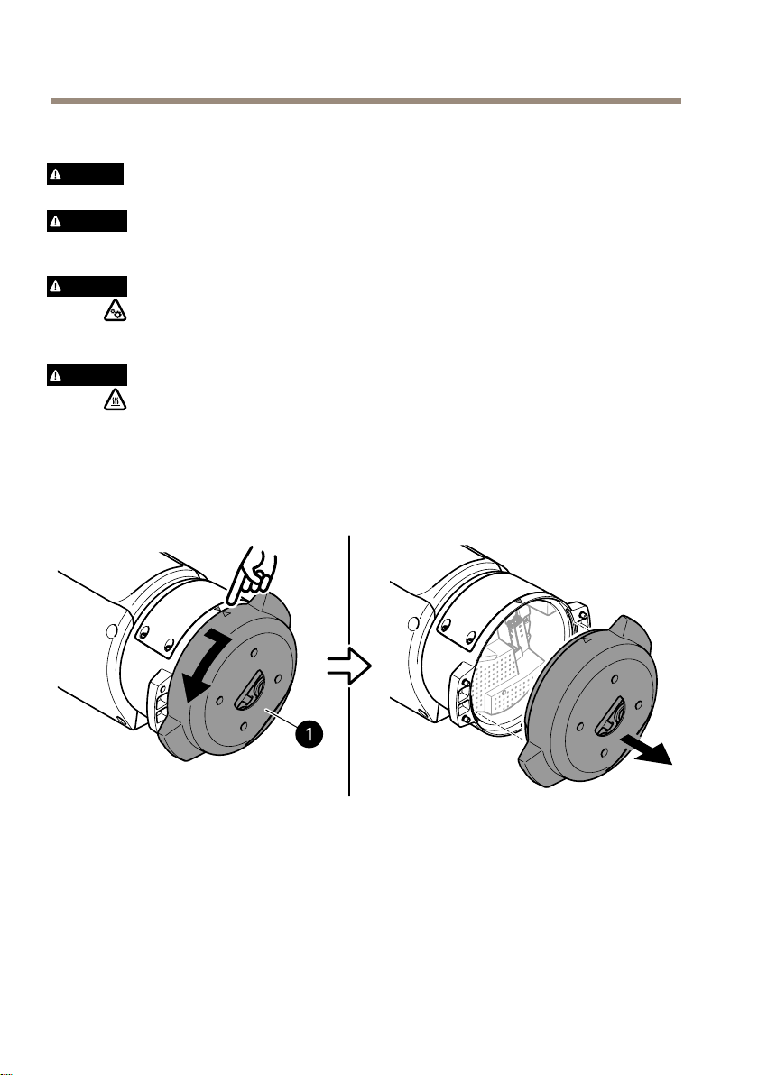
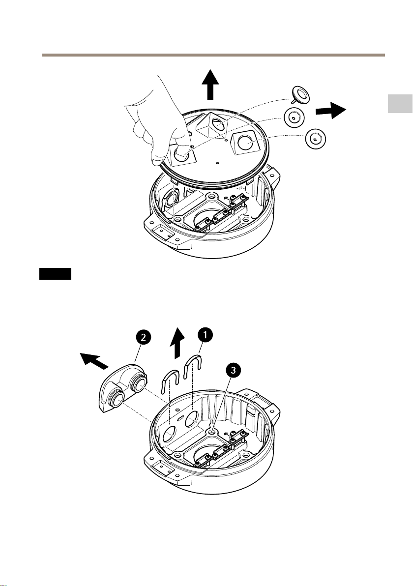
Mountthebaseunit
1
Baseunit
1.Removethefourbaseunitscrews(T30).
2.Simultaneouslypullandturnthebaseunitcounterclockwiseuntilthearrowsonthebase
unitandtherestofthepositioningunitalign.
3.Removethebaseunit.
12
Page 13
AXIST99A12PositioningUnit24VAC/DC
NO
TICE
NO NO
TICE TICE
Donotusesharptoolswhenyouremovethetransparentbaseunitcover.
4.Removethetransparentbaseunitcover.
EN
1
2
Conduitcoverclip
Conduitcover
13
Page 14
AXIST99A12PositioningUnit24VAC/DC
3
Screwhole(x4)
5.Forconduitinstallationsonly:removethetwoconduitcoverclipsfollowedbythe
conduitcover.
6.Attachthebaseunittothemountingsurfacewithappropriatefastenersinthefour
screwholes.
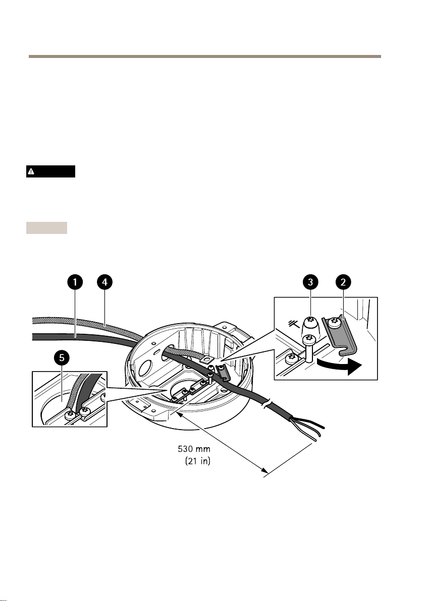
Routethecables
WARNING
Riskofelectricshock.Theproductshallbegroundedusingboththeprotectivegrounding
wireinthepowercableandthegroundingbraid.Makesurebothendsoftheprotective
groundingwireandthegroundingbraidareincontactwiththeirrespectivegrounding
surfaces.
Important
Useonlycablesthatcomplywiththespeciedcablearea.Formoreinformation,see
Cablethicknessonpage28.
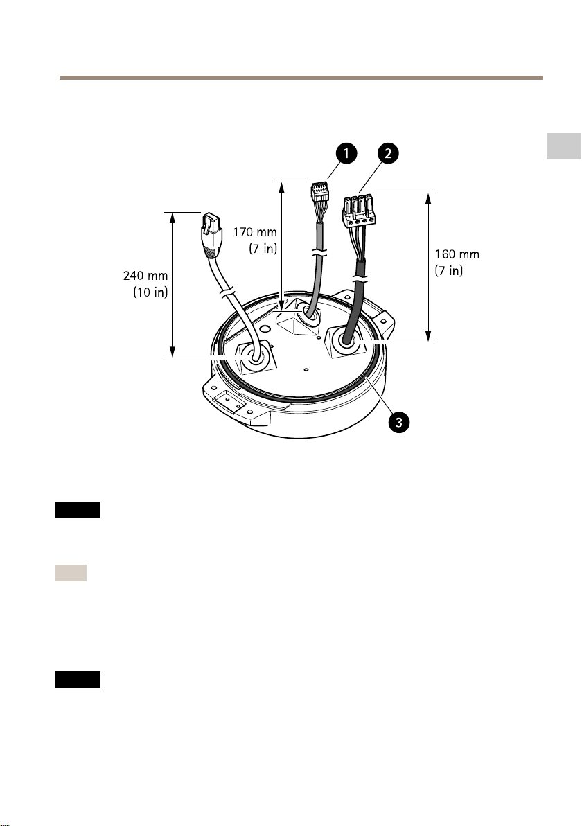
1
Powercable(notincluded)
2
Strainrelief
3
Groundingscrew
4
Groundingbraid(notincluded)
5
Bottomcablehole
14
Page 15
AXIST99A12PositioningUnit24VAC/DC
1.Installtheoptionalconduitadapters(notincluded).
2.Connectthegroundingbraidtothegroundingscrew.
3.Insertthepowercable,I/Ocableandnetworkcablethroughtheholeinthebaseunitas
shownintheillustrationabove.Alternativelyinsertthemthroughthebottomcablehole.
4.Insertthepowercablethroughthestrainreliefwithadistanceof530mm(21in)from
thestrainrelieftotheendofthecable.
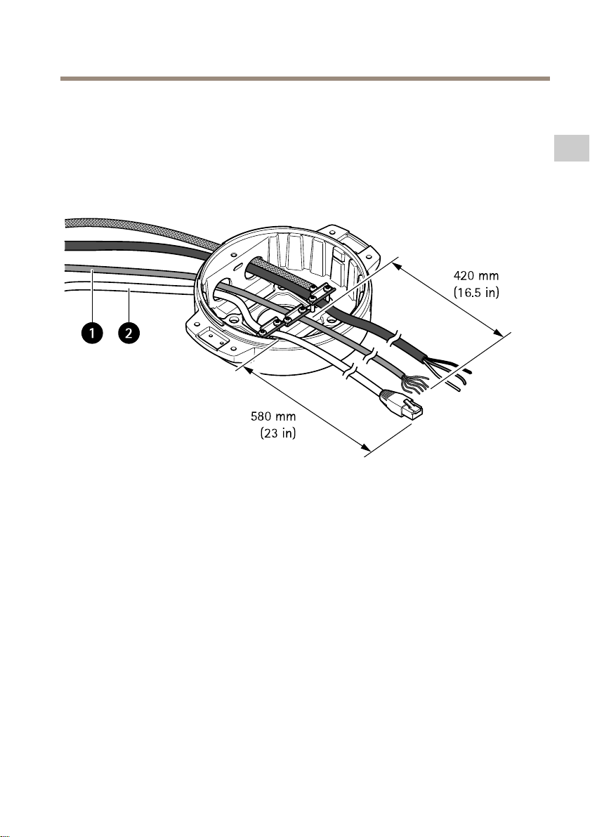
EN
1
I/Ocable(optional,notincluded)
2
Networkcable(notincluded)
5.InserttheI/Ocable(optional)throughthestrainreliefwithadistanceof420mm(16.5
in)fromthestrainrelieftotheendofthecable.
6.Insertthenetworkcable(opticalbercableand/orRJ45cable)throughthestrainrelief
withadistanceof580mm(23in)fromthestrainrelieftotheendoftheconnector.
Formoreinformationondifferentnetworkconnectivityoptions,seeInstallthenetwork
linkonpage18.
7.Closeandtightenthethreestrainreliefs.
15
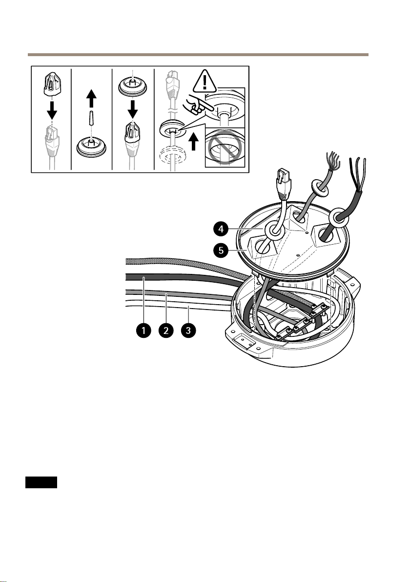
Page 16
AXIST99A12PositioningUnit24VAC/DC
1
Powercable(notincluded)
2
I/Ocable(optional,notincluded)
3
Networkcable(notincluded)
4
Cablegasket
5
Transparentbaseunitcover
8.Fitcablegasketsonthecables.SeeCablethicknessonpage28.
9.Insertthepower,I/Oandnetworkcablesincludingthecablegasketsthroughtheholesin
thetransparentbaseunitcoverandarrangethecablesasshownintheillustrationabove.
NO
TICE
NO NO
TICE TICE
IfyouusebothanopticalbrecableandanRJ45cablefornetworkconnectivity,routethe
opticalbrecablethroughthesamecablegasketastheI/Ocable.Applyasealantbetween
thecablesandthecablegaskettopreventleakage.Formoreinformationondifferent
networkconnectivityoptions,seeInstallthenetworklinkonpage18.
16
Page 17
AXIST99A12PositioningUnit24VAC/DC
10.Placethetransparentbaseunitcoveronthebaseunitandtthecablegasketsinside
theholes.
EN
1
I/Oconnector
2
Powerconnector
3
O-ring
NO
TICE
NO NO
TICE TICE
Tonotaccidentallydisconnecttheunitfrompowerifthecableispulled,lettheprotective
groundingwirebeabout10mm(0.4in)longerthantheothertwowires(inthepower
cable).
Note
Tomaketheinstallationaseasyaspossible,werecommendyoutostripapproximately90
mm(3.5in)ofthepowercablejacketand70mm(2.8in)oftheI/Ocablejacket.
11.InstallthepowerandI/Oconnectors.
12.Adjustthenetwork,I/Oandpowercablessothatthedistancefromthecablegasketto
theendoftheconnectoris240mm(10in),170mm(7in),and160mm(7in)respectively.
NO
TICE
NO NO
TICE TICE
MakesurethattheO-ringisttedcorrectlyaroundthetransparentbaseunitcover.
17
Page 18
AXIST99A12PositioningUnit24VAC/DC
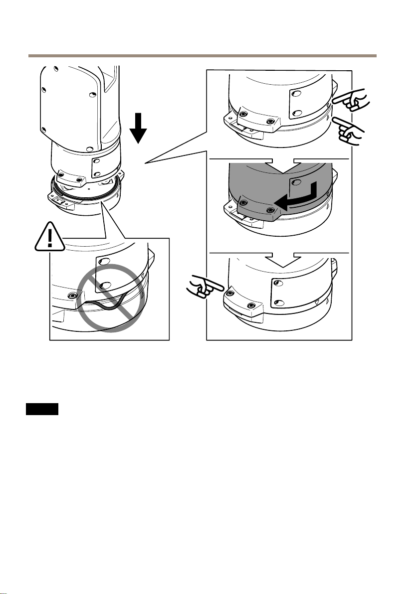
13.Placethepositioningunitonthebaseunit.Makesurethatthearrowsonthetwo
unitsarealigned.
14.Turnthepositioningunitclockwisebacktoitsoriginalpositionandtightenthefour
baseunitscrews(torque3.0Nm).
NO
TICE
NO NO
TICE TICE
Makesurethatthecablesdon’tgetpinchedwhenyouassemblethetwounits.
18
Page 19

AXIST99A12PositioningUnit24VAC/DC
Installthenetworklink
Youcanchoosebetweendifferentoptionswhenyouinstallthenetworklink:
•A:viaanopticalberorRJ45cableconnectedtotheSFPmodule(witharespective
connector)intheSFPslot.
•B:viaanRJ45cableconnectedtothexedRJ45connector.
•C:viabothoftheabove,inwhichcasetheSFPmoduleconnectionfunctionsasthe
primarynetworklink,andthexedRJ45connectionfunctionsasthefail-overlink.
Formoreinformationonnetworkconnectorlocations,seeProductoverviewonpage10.
Note
•SFPmoduleisnotincluded.FormoreinformationonavailableSFPmodules,seeaxis.com
•IfyouinstallanetworklinkonlyviatheopticalbercableusingtherespectiveSFP
module,itworksasastand-alonesolutionforlongrangecablinginstallations.
EN
Installthecamera
NO
TICE
NO NO
TICE TICE
•Thisproductsupportsseveralcameramodels.Foracompletelistofsupportedcameras,
seetheproductpageataxis.com.
•Forinstructionsonhowtoopenthecameracover,seethecamera’sinstallationguide.
19
Page 20
AXIST99A12PositioningUnit24VAC/DC
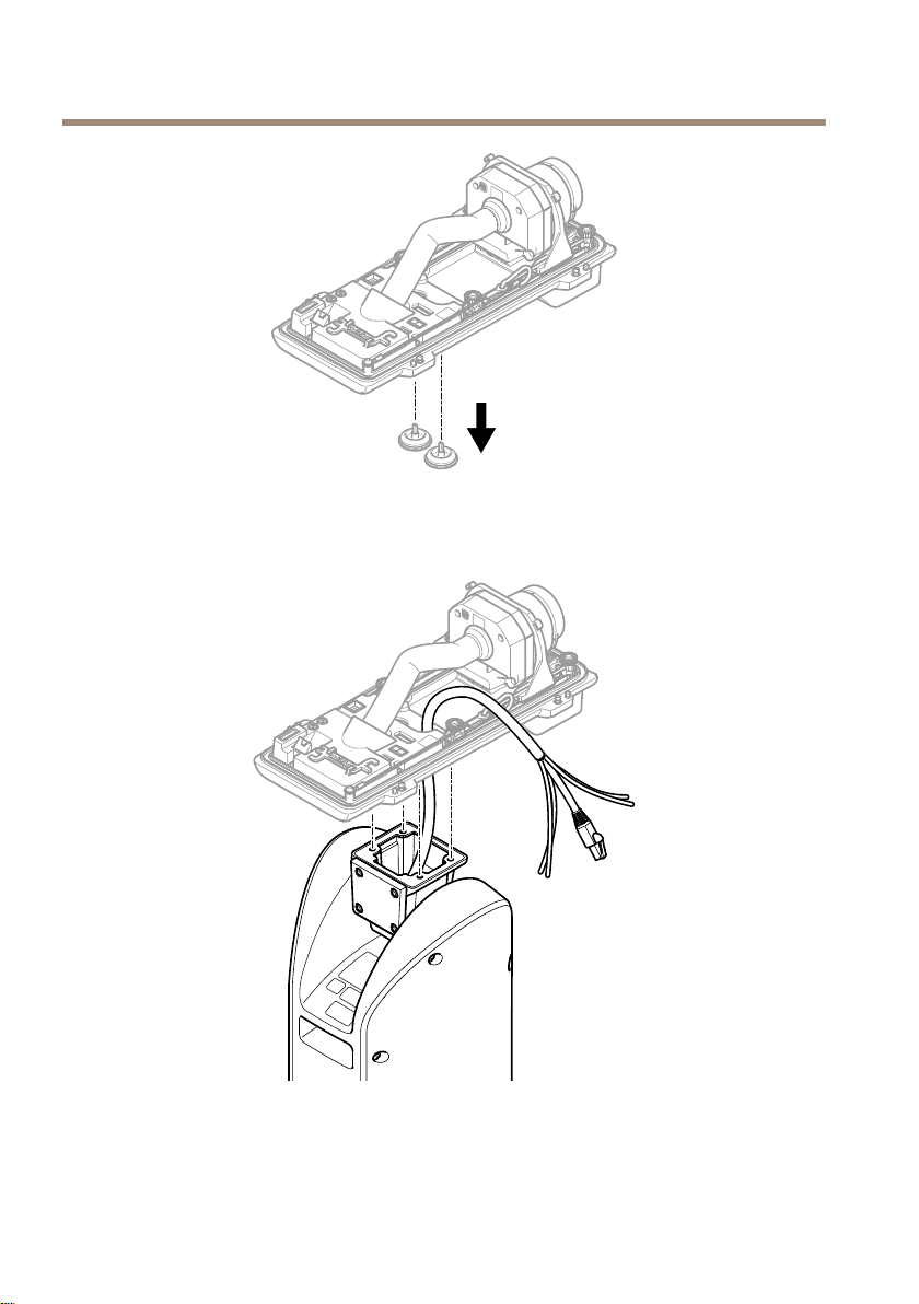
1.Removethecablegasketsfromthecamera’sbottomcover.
2.Insertthenetwork/power/serialinterfacecabletroughtheholesinthebottomcover.
3.Fitthebottomcoveronthepositioningunit.
20
Page 21

AXIST99A12PositioningUnit24VAC/DC
EN
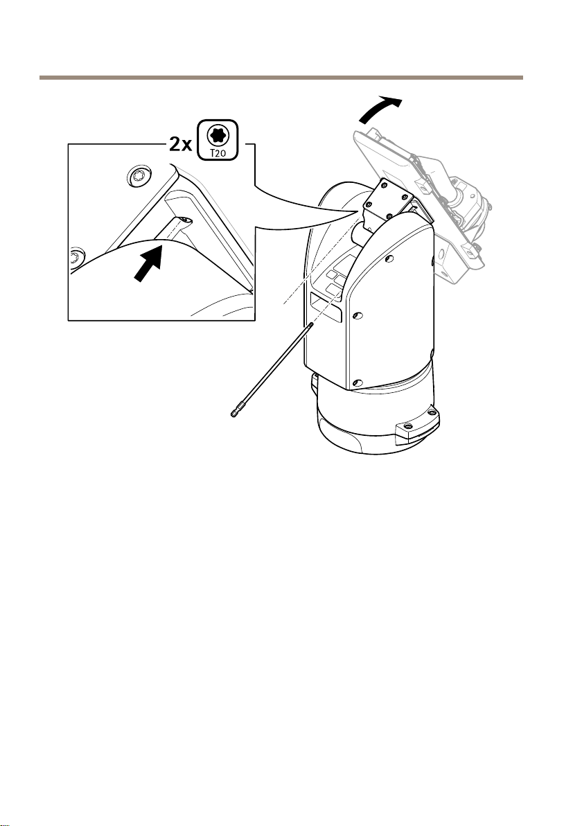
4.Tiltthebottomcoverbackwardtoitsendpositionandtightenthetwofrontscrewsof
thepositioningunit(T20,torque3.0Nm).
21
Page 22
AXIST99A12PositioningUnit24VAC/DC
5.Tiltthebottomcoverforwardtoitsendpositionandtightenthetworearscrewsof
thepositioningunit(T20,torque3.0Nm).
6.Connectthecameranetwork,serialinterfaceandpowercablesaccordingtothecamera’s
installationguide.Formoreinformationoncablespecications,seeCamerapowercable
onpage29andCameraserialinterfacecableonpage29.
7.Finalizethecamerainstallationaccordingtothecamera’sinstallationguide.
22
Page 23

AXIST99A12PositioningUnit24VAC/DC
Connectthecables
1.Loosenthefourlidscrews(T20)andremovethelid.
EN
1
Inputpowerconnector
2
I/Oconnector
3
RJ45connector
4
SFPslotforSFPmodule(SFPmodulenotincluded)
2.Connectthenetwork(opticalbreand/orRJ45),I/Oandpowercables.Formore
informationondifferentnetworkconnectivityoptions,seeInstallthenetworklinkon
page18.
3.Returnthelidtoitspositionandtightenthefourlidscrews(torque3.0Nm).
4.Removetheprotectivecover.
5.Applypowertotheproduct.
23
Page 24

AXIST99A12PositioningUnit24VAC/DC
InstallthePTZdriver
Thisproductsupportsseveraldevices.Foracompletelistofsupporteddevices,seeaxis.com
1.Gotothecamera’swebpage.
2.Intheinstallationwizard,gotoSelectaPTZmodeandselectPTZdriverfromthe
drop-downlist.
3.Onceyou’veaccessedtheliveview,gotoSettings>System>Accessories.
4.Selectoneofthefollowingactions:
4.1IfthePTZdriverisnotuploaded,selectUploaddriver.
4.2IfthePTZdriverisuploaded,gotoSelectdrivertouseandselectPTZdriver
fromthedrop-downlist.
5.Selectavideochannel.
6.EntertheDeviceidandselectDevicetypefromthedropdown-list.Todecidewhich
devicetypetouse,seethedocumentationsuppliedwiththePTZdriver.
7.GotothePTZtabandcheckthatthePTZsettingsareavailable.
24
Page 25

AXIST99A12PositioningUnit24VAC/DC
Specifications
Connectors
Networkconnector
RJ45Ethernetconnector.
SFPconnector.
NO
TICE
NO NO
TICE TICE
Theproductshallbeconnectedusingashieldednetworkcable(STP)oranopticalber
cable.Allcablesconnectingtheproducttothenetworkshallbeintendedfortheir
specicuse.Makesurethatthenetworkdevicesareinstalledinaccordancewith
themanufacturer’sinstructions.Forinformationaboutregulatoryrequirements,see
Electromagneticcompatibility(EMC)onpage4.
I/Oconnector
Digitalinput-Forconnectingdevicesthatcantogglebetweenanopenandclosedcircuit,for
examplePIRsensors,door/windowcontacts,andglassbreakdetectors.
Digitaloutput-ForconnectingexternaldevicessuchasrelaysandLEDs.Connecteddevices
canbeactivatedbytheVAPIX®ApplicationProgrammingInterface,troughaneventorfrom
theproduct’swebpage.
EN
Adigitallightsensor-Forreceivingavalueoftheambientlightintensityfromanexternallight
sensor.Thisisusedtocontroltheproduct’sdayandnightfunctionality.
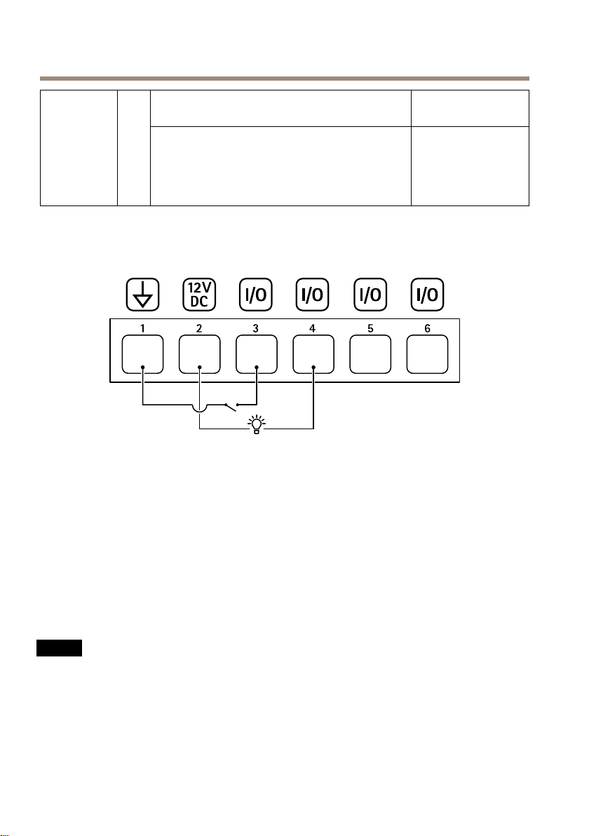
6-pincongurableterminalblock
FunctionPinNotes
DCground
DCoutput
1
2
Canbeusedtopowerauxiliaryequipment.
Note:Thispincanonlybeusedaspowerout.
Specications
0VDC
12VDC
Maxload=50mA
25
Page 26
AXIST99A12PositioningUnit24VAC/DC
3–
Digitalinput–Connecttopin1toactivate,or
6
(Inputor
Output)
Example
1
2
3
4
5
6
leaveoating(unconnected)todeactivate.
Digitaloutput–Internallyconnectedtopin1(DC
ground)whenactive,andoating(unconnected)
wheninactive.Ifusedwithaninductiveload,e.g.,
arelay,connectadiodeinparallelwiththeload,
toprotectagainstvoltagetransients.
DCground
DCoutput12V,max50mA
I/Oconguredasinput
I/Oconguredasoutput
CongurableI/O
CongurableI/O
0tomax30VDC Congurable
0tomax30VDC,
opendrain,100mA
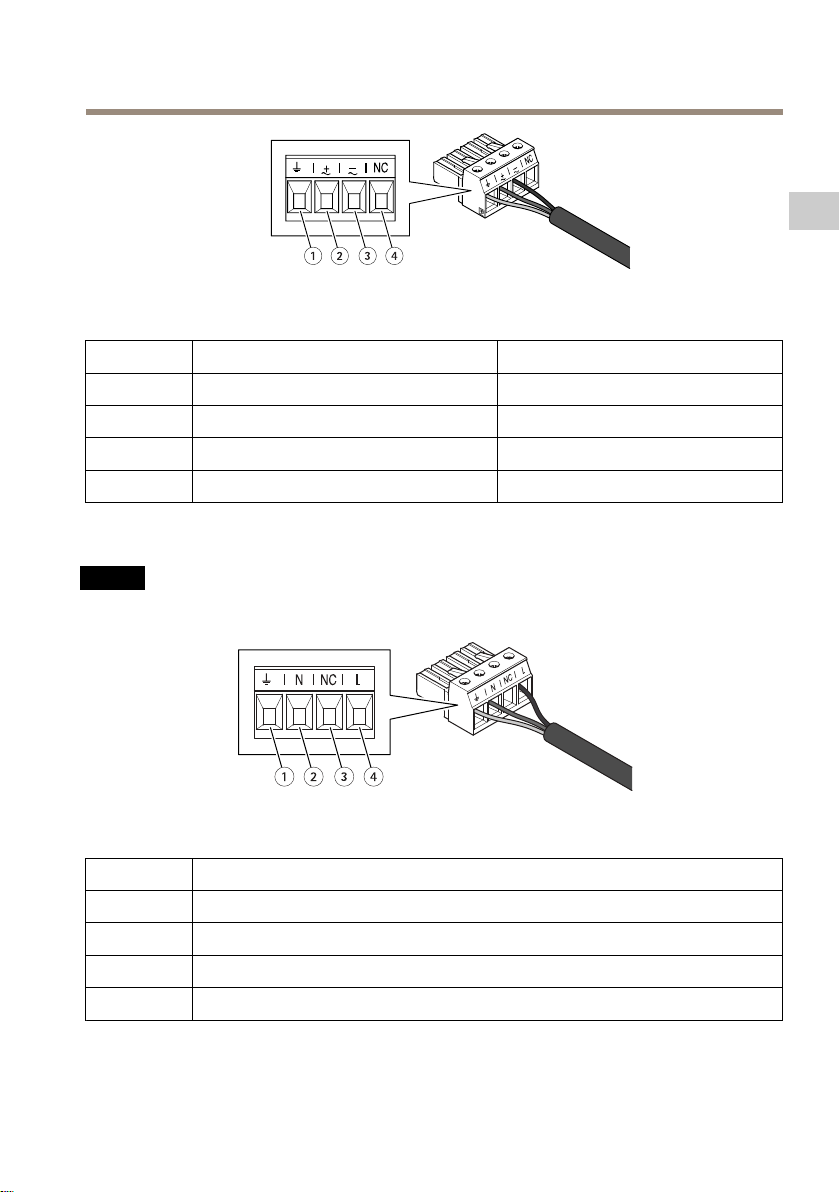
Powerconnector
4-pinterminalblockforpowerinput.
24VAC/DCpowerconnector
NO
TICE
NO NO
TICE TICE
Thissectionisvalidforproductspoweredby24VACand24VDConly.
26
Page 27
AXIST99A12PositioningUnit24VAC/DC
Thistableisonlyvalidforthe24VACandthe24VDCpowerconnectors.
EN
Position
1
2
3
4
240VACpowerconnector
NO
TICE
NO NO
TICE TICE
Thissectionisvalidforproductspoweredby100–240VAConly.
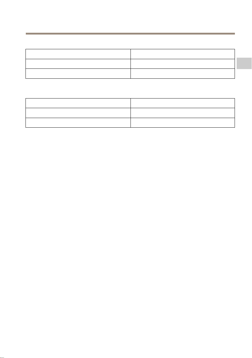
Thistableisonlyvalidforthe240VACpowerconnector.
Position
1
2
3
4
24VAC24VDC
ProtectiveearthProtectiveearth
24VACPhase
24VACNeutral
NotconnectedNotconnected
100–240VAC
Protectiveearth
240VACNeutral
Notconnected
240VACPhase
+24V
0V
27
Page 28
AXIST99A12PositioningUnit24VAC/DC
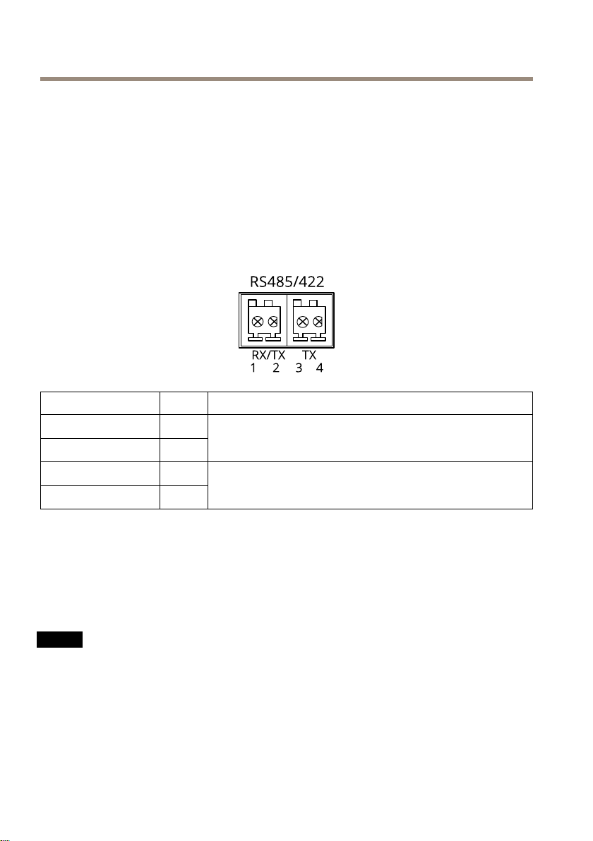
RS485/RS422connector
Two2-pinterminalblocksforRS485/RS422serialinterfaceusedtocontrolauxiliaryequipment
suchaspan-tiltdevices.
Theserialportcanbeconguredtosupport:
•Two-wireRS485halfduplex
•Four-wireRS485fullduplex
•Two-wireRS422simplex
•Four-wireRS422fullduplexpointtopointcommunication
FunctionPinNotes
RS485/RS422RX/TXA
RS485/RS422RX/TXB
RS485/RS422TXA
RS485/RS422TXB
1
2
3
4
(RX)ForfullduplexRS485/RS422
(RX/TX)ForhalfduplexRS485
(TX)ForfullduplexRS485/RS422
Cables
Cablethickness
Thecablediameter,whenusingcablegasketsprovidedwiththeproduct,shouldbeintherangeof
5to11mm(0.2to0.4in).
NO
TICE
NO NO
TICE TICE
•Usecablesthatkeepwithinthespeciedcablearea
•Selectcablesincompliancewithyourlocalregulations
•Makesureallcableholesareproperlysealed
•Usecablegasketsorcableglandsthatmatchboththecableholeandthecablearea
Forinformationaboutaccessories,suchascablegasketsandcableglandsthatallowforother
cableareas,seewww.axis.com
28
Page 29
AXIST99A12PositioningUnit24VAC/DC
Cameraserialinterfacecable
CablecolorSpecication
White
GreenRS485B
Camerapowercable
CablecolorSpecication
Red
Black0V
RS485A
+24VDC
29EN30
Page 30

Page 31

AXIST99A12PositioningUnit24VAC/DC
Informationssurlasécurité
Niveauxderisques
DANGER
Indiqueunesituationdangereusequi,siellen'estpasévitée,entraîneraledécèsoudes
blessuresgraves.
AVERTISSEMENT
Indiqueunesituationdangereusequi,siellen'estpasévitée,pourraitentraînerledécès
oudesblessuresgraves.
ATTENTION
Indiqueunesituationdangereusequi,siellen'estpasévitée,pourraitentraînerdes
blessureslégèresoumodérées.
VIS
A AAVIS VIS
Indiqueunesituationqui,siellen'estpasévitée,pourraitendommagerl'appareil.
Autresniveauxdemessage
Important
Indiquelesinformationsimportantes,nécessairespourassurerlebonfonctionnementde
l’appareil.
Remarque
Indiquelesinformationsutilesquipermettrontd’obtenirlefonctionnementoptimalde
l’appareil.
FR
Consignesdesécurité
DANGER
Risquedechocélectrique.Touslescâblesdoiventêtremishorstensionavantl'installation
ouuneinterventiondemaintenancesurleproduit.
ATTENTION
Piècesmobiles.Risquedeblessure.Restezàl'écartduproduitlorsqu'ilest
fonctionnement.Débranchezl'alimentationélectriqueavantd'installerleproduitou
d'effectuersonentretien.
ATTENTION
Surfaceschaudes.Risquedeblessure.Netouchezpasleproduitlorsqu'ilestencours
defonctionnement.Débranchezl'alimentationélectriqueetlaissezlessurfacesrefroidir
avantd'effectuerl'entretienduproduit.
VIS
A AAVIS VIS
•LeproduitAxisdoitêtreutiliséconformémentauxloisetrèglementslocaux.
•ConserverceproduitAxisdansunenvironnementsecetventilé.
31
Page 32

AXIST99A12PositioningUnit24VAC/DC
•NepasexposerceproduitAxisauxchocsouauxfortespressions.
•Nepasinstallerceproduitsurdespoteaux,supports,surfacesoumursinstables.
•Utiliseruniquementdesoutilsrecommandéspourl'installationdel'appareilAxis.
L'applicationd'uneforceexcessivesurl'appareilavecdesoutilspuissantspourrait
l'endommager.
•Nepasutiliserdeproduitschimiques,desubstancescaustiquesoudenettoyants
pressurisés.
•Utiliserunchiffonpropreimbibéd'eaupurepourlenettoyage.
•Utiliseruniquementdesaccessoiresconformesauxcaractéristiquestechniquesdevotre
produit.IlspeuventêtrefournisparAxisouuntiers.Axisrecommanded'utiliserun
équipementd'alimentationAxiscompatibleavecvotreproduit.
•UtiliseruniquementlespiècesderechangefourniesourecommandéesparAxis.
•Nepasessayerderéparervous-mêmeceproduit.Contacterl'assistancetechniqued'Axis
ouvotrerevendeurAxispourdesproblèmesliésàl'entretien.
•Utilisezuncâbledemiseàlaterredecouleurjaune/vertd'aumoins0,5mm
Transport
VIS
A AAVIS VIS
•LorsdutransportduproduitAxis,utilisezl'emballaged'origineouunéquivalentpour
éviterd'endommagerleproduit.
2
ou20AWG.
32
Page 33

Contenudel’emballage
•Unitédepositionnement
•Connecteurd'alimentation
•Connecteurd'E/S
•EmboutTorx®T20(long)etT30
AXIST99A12PositioningUnit24VAC/DC
FR
33
Page 34

AXIST99A12PositioningUnit24VAC/DC
Productoverview
1
Unitédepositionnement(inclinaison)
2
Unitédepositionnement(panoramique)
3
Opercule
4
Unitédebase
5
Caméra(nonincluse)
34
Page 35

AXIST99A12PositioningUnit24VAC/DC
1
Câblesdeprojecteur(nedoiventpasêtreutilisés)
2
Câbleélectriquedelacaméra
3
Câbleréseaudelacaméra
4
Câbleinterfacesériedelacaméra
5
Connecteurd'alimentationd'entrée
6
Connecteurd'E/S
7
ConnecteurRJ45
8
EmplacementSFPpourmoduleSFP(moduleSFPnoninclus)
FR
35
Page 36

AXIST99A12PositioningUnit24VAC/DC
Commentinstallerleproduit
DANGER
Risquedechocélectrique.Touslescâblesdoiventêtrehorstensionavantd'installer
leproduit.
ATTENTION
Lesconnexionsélectriquesetlesinstallationsdeconduitesdoiventêtreeffectuéesparun
électriciencertiéetconformémentauxréglementationslocales.
ATTENTION
Risquesdeblessures.Piècesmobiles.Restezàl'écartduproduitlorsqu'ilestencours
defonctionnement.Débranchezl'alimentationélectriqueavantd'installerleproduitou
d'effectuersonentretien.
ATTENTION
Risquesdeblessures.Surfaceschaudes.Netouchezpasleproduitlorsqu'ilesten
coursdefonctionnement.Débranchezl'alimentationélectriqueetlaissezlessurfaces
refroidiravantd'effectuerl'entretienduproduit.
Montagedel'unitédebase
1
Unitédebase
1.Déposerlesquatrevisdel'unité(T30).
2.Tirezettournezsimultanémentl'unitédebasedanslesensanti-horairejusqu'àceque
lesèchessurl'unitédebaseetlerestedel'unitédepositionnements'alignent.
3.Déposezl'unitédebase.
36
Page 37

AXIST99A12PositioningUnit24VAC/DC
VIS
A AAVIS VIS
N'utilisezpasd'outilstranchantslorsquevousdéposezlecouvercletransparentdel'unité
debase.
4.Déposezlecouvercletransparentdel'unitédebase.
FR
1
Clipducachedeconduit
37
Page 38

AXIST99A12PositioningUnit24VAC/DC
2
Cachedeconduit
3
Troudevis(x4)
5.Pourdesinstallationsdeconduituniquement:déposezlesdeuxclipsducachede
conduitsuivisparlecacheduconduit.
6.Fixezl'unitédebaseàlasurfacedemontageaveclesélémentsdexationappropriés
danslesquatretrousdevis.
Acheminementdescâbles
AVERTISSEMENT
Risquedechocélectrique.Leproduitdoitêtremisàlaterreàl'aideducâbledemiseà
laterredeprotectionducâbled'alimentationetdelatressedeterre.Assurez-vousque
lesdeuxextrémitésducâbledemiseàlaterredeprotectionetlatressedeterresonten
contactaveclessurfacesdemiseàlaterrecorrespondantes.
Important
Utilisezuniquementdescâblesconformesàlazonespéciée.Pourensavoirplus,consultez
Épaisseurducâbleàlapage52.
1
Câbled’alimentation(nonfourni)
2
Réducteurdetension
3
visdemiseàlaterre
4
Tressedeterre(nonfournie)
38
Page 39

AXIST99A12PositioningUnit24VAC/DC
5
passageducâbleinférieur
1.Installezlesadaptateursdeconduitenoption(nonfournis).
2.Reliezlatressedeterreàlavisdemiseàlaterre.
3.Insérezlecâbled'alimentation,lecâbled'E/Setlecâbleréseauàtraversl'oricede
l'unitédebasecommeillustréci-dessus.Vouspouvezaussilesinsérerdansl'orice
ducâbleinférieur.
4.Insérezlecâbled'alimentationàtraversleréducteurdetensionavecunedistancede
530mm(21po)depuisleréducteurdetensionjusqu'àl'extrémitéducâble.
FR
1
CâbleE/S(enoption,nonfourni)
2
Câbleréseau(noninclus)
5.Insérezlecâbled'E/S(enoption)àtraversleréducteurdetensionavecunedistancede
420mm(16,5po)depuisleréducteurdetensionjusqu'àl'extrémitéducâble.
6.Insérezlecâbleréseau(câblebreoptiqueet/oucâbleRJ45)àtraversleréducteurde
tensionavecunedistancede580mm(23po)depuisleréducteurdetensionjusqu'à
l'extrémitéduconnecteur.Pourplusd'informationssurlesdifférentesoptionsde
connectivitéréseau,consultezInstallationdelaliaisonréseauàlapage42.
7.Fermezetserrezlestroisreliefsdetraction.
39
Page 40

AXIST99A12PositioningUnit24VAC/DC
1
Câbled'alimentation(noninclus)
2
CâbleE/S(enoption,nonfourni)
3
Câbleréseau(noninclus)
4
Jointdecâble
5
Couvercletransparentdel'unitédebase
8.Placezlesjointssurlescâbles.Cf.Épaisseurducâbleàlapage52.
9.Insérezlescâblesd'alimentation,d'E/Setréseauycomprislesjointsàtraverslesorices
ducouvercletransparentdel'unitédebaseetdisposezlescâblescommeillustré
ci-dessus.
VIS
A AAVIS VIS
SivousutilisezuncâbleàbreoptiqueetuncâbleRJ45pourlaconnectivitéréseau,
acheminezlecâbleàbreoptiqueàtraverslemêmejointquelecâbled'E/S.Appliquez
unjointentrelescâblesetlejointdecâblepourempêchertoutefuite.Pourplus
40
Page 41

AXIST99A12PositioningUnit24VAC/DC
d'informationssurlesdifférentesoptionsdeconnectivitéréseau,consultezInstallation
delaliaisonréseauàlapage42.
10.Placezlecouvercletransparentdel'unitédebasesurcelle-cietplacezlesjointsdans
lesorices.
FR
1
Connecteurd'E/S
2
Connecteurd’alimentation
3
Jointtorique
VIS
A AAVIS VIS
Pournepasdébrancheraccidentellementl'unitédel'alimentationélectriquesilecâbleest
tiré,lecâbledemiseàlaterredeprotectiondoitêtrepluslongd'environ10mm(0,4po)
quelesdeuxautresls(danslecâbled'alimentation).
Remarque
Pourfaciliterl'installation,nousvousrecommandonsdedénuderenviron90mm(3,5po)de
lagaineducâbled'alimentationet70mm(2,8po)delagainedecâbled'E/S.
11.Installezlesconnecteursd'alimentationetd'E/S.
12.Réglezlescâblesréseau,d'E/Setd'alimentationdesortequeladistancedepuislejoint
ducâblejusqu'àl'extrémitéduconnecteursoitrespectivementde240mm(10po),
170mm(7po)et160mm(7po).
41
Page 42

AXIST99A12PositioningUnit24VAC/DC
VIS
A AAVIS VIS
Assurez-vousquelesjointstoriquessontcorrectementxésautourducouvercle
transparentdel'unitédebase.
13.Placezl'unitédepositionnementsurl'unitédebase.Assurez-vousquelesèchesdes
deuxunitéssontalignées.
14.Tournezl'unitédepositionnementdanslesensdesaiguillesd'unemontrejusqu'àsa
positiond'origineetserrezlesquatrevisdel'unitédebase(couplede3,0Nm).
VIS
A AAVIS VIS
Assurez-vousdenepaspincerlescâbleslorsdel'assemblagedesdeuxunités.
42
Page 43

AXIST99A12PositioningUnit24VAC/DC
Installationdelaliaisonréseau
Vouspouvezchoisirentreplusieursoptionslorsquevousinstallezlaliaisonréseau:
•A:viauncâbleàbreoptiqueouuncâbleRJ45raccordéaumoduleSFP(avec
connecteurcorrespondant)surl'emplacementSFP.
•B:viauncâbleRJ45raccordéauconnecteurRJ45xe.
•C:vialesdeuxsolutionsci-dessus,auquelcaslaconnexiondumoduleSFPfonctionne
commelaliaisonréseauprimaireetlaconnexionRJ45xefonctionnecommelaliaison
desecours.
FR
Pourplusd'informationssurlesemplacementsdesconnecteursréseau,voirProductoverviewà
lapage34.
Remarque
•LemoduleSFPn'estpasfourni.Pourplusd’informationssurlesmodulesSFP,consultezle
siteaxis.com
•Sivousinstallezuneliaisonréseauuniquementvialecâbleàbreoptiqueàl'aidedu
moduleSFPrespectif,ellefonctionnecommeunesolutionautonomepourlesinstallations
decâblagelonguedistance.
Installationdelacaméra
VIS
A AAVIS VIS
•CeproduitAxisestcompatibleavecplusieursmodèlesdecaméras.Rendez-voussurla
pageproduitssuraxis.compourconsulterlalistecomplètedescamérasprisesencharge.
•Poursavoircommentouvrirlecouvercledelacaméra,reportez-vousauguide
d'installationdelacaméra.
43
Page 44

AXIST99A12PositioningUnit24VAC/DC
1.Retirezlesjointsdecâbleducouvercleinférieurdelacaméra.
2.Insérezlecâbled'interfaceréseau/alimentation/sérieàtraverslestrousducouvercle
inférieur.
3.Montezlecouvercleinférieursurl'unitédepositionnement.
44
Page 45

AXIST99A12PositioningUnit24VAC/DC
FR
4.Inclinezlecouvercleinférieurversl'arrièrejusqu'àsapositionnaleetserrezlesdeuxvis
avantdel'unitédepositionnement(T20,couple3Nm).
45
Page 46

AXIST99A12PositioningUnit24VAC/DC
5.Inclinezlecouvercleinférieurverssapositionnaleetserrezlesdeuxvisarrièrede
l'unitédepositionnement(T20,couple3Nm).
6.Branchezlescâblesréseau,interfacesérieetd'alimentationdelacaméraconformément
auguided'installationdelacaméra.Pourplusd’informationsconcernantles
caractéristiquestechniquesdescâbles,consultezCâbleélectriquedelacaméraàlapage
53etCâbleinterfacesériedelacaméraàlapage53.
7.Finalisezl'installationdelacaméraconformémentauguided'installationdelacaméra.
46
Page 47

AXIST99A12PositioningUnit24VAC/DC
Branchezlescâbles
1.Desserrezlesquatrevisducouvercle(T20)etretirezlecouvercle.
FR
1
Connecteurd'alimentationd'entrée
2
ConnecteurE/S
3
ConnecteurRJ45
4
EmplacementSFPpourmoduleSFP(moduleSFPnoninclus)
2.Branchezlecâbleréseau(breoptiqueet/ouRJ45),E/Setd'alimentation.Pourplus
d'informationssurlesdifférentesoptionsdeconnectivitéréseau,consultezInstallation
delaliaisonréseauàlapage42.
3.Remettezlecouvercleenplaceetserrezlesquatrevisducouvercle(coupledeserrage
3,0Nm).
4.Retirezlecouvercledeprotection.
47
Page 48

AXIST99A12PositioningUnit24VAC/DC
5.Mettezleproduitsoustension.
InstallationdupilotePTZ
Cetproduitestcompatibleavecplusieursappareils.Pourconnaîtrelalistecomplètedesappareils
prisencharge,consultezlesiteaxis.com.
1.AccédezàlapageWebdelacaméra.
2.Dansl'Assistantd'installation,accédezàSélectionneunmodePTZetsélectionnez
PilotePTZdanslalistedéroulante.
3.Unefoisquevousavezaccédéàlavidéoendirect,accédezàParamètres>Système
>Accessoires.
4.Sélectionnezl'unedesactionssuivantes:
4.1SilepilotePTZn'estpastéléchargé,sélectionnezTéléchargerlepilote.
4.2SivoustéléchargezlepilotePTZ,accédezàSélectionnerlepiloteàutiliser
etsélectionnezPilotePTZdanslalistedéroulante.
5.Sélectionneruncanalvidéo.
6.Saisissezl'IDdupériphériqueetsélectionnezTypedepériphériquedanslaliste
déroulante.Pourdéterminerletyped'appareilàutiliser,consultezladocumentation
fournieaveclepilotePTZ.
7.Accédezàl'ongletPTZetvériezquelesparamètresPTZsontdisponibles.
48
Page 49

Specifications
Connecteurs
Connecteurréseau
AXIST99A12PositioningUnit24VAC/DC
ConnecteurEthernetRJ45.
ConnecteurSFP.
VIS
A AAVIS VIS
Leproduitdoitêtreconnectéàl'aided'uncâbleréseaublindé(STP)oud'uncâbleà
bresoptiques.Touslescâblesreliantleproduitaucommutateurréseaudoiventêtre
destinésàleurusagespécique.Assurez-vousquelespériphériquesréseausontinstallés
conformémentauxinstructionsdufabricant.Pourplusd’informationssurlesexigences
réglementaires,consultezElectromagneticcompatibility(EMC)onpage4.
Connecteurd’E/S
Entréenumérique-Pourconnecterdesdispositifspouvantpasserd'uncircuitouvertàuncircuit
fermé,parexemplecapteursinfrarougepassifs,contactsdeporte/fenêtreetdétecteursdebrisde
verre.
Sortienumérique-Permetdeconnecterdesdispositifsexternes,commedesrelaisoudesvoyants.
Lesappareilsconnectéspeuventêtreactivésparl’interfacedeprogrammationVAPIX®,viaun
événementouàpartirdelapageWebduproduit.
Uncapteurdelumièrenumérique-Pourrecevoirunevaleurdel’intensitélumineuseambiante
depuisuncapteurdelumièreexterne.Cettevaleurestutiliséepourcontrôlerlafonctionjour/nuit.
Blocterminalcongurableà6broches
FonctionB-
MasseduCC
SortieCC
Remarques
roche
1
2
Peutserviràalimenterlematérielauxiliaire.
Remarque:cettebrochenepeutêtreutiliséeque
commesortied’alimentation.
Caractéristiques
0VCC
12VCC
Chargemax.=
50mA
FR
49
Page 50

AXIST99A12PositioningUnit24VAC/DC
Congurable
(entréeou
sortie)
Exemple
3–
Entréenumérique-Connectez-vousàlabroche1
6
pouractiveroulaissernonconnectépour
désactiver.
Sortienumérique–Connexioninterneàla
broche1(terreCC)encasd’activation,et
ottante(déconnectée)encasdedésactivation.
Encasd'utilisationavecunechargeinductive,
parexempleunrelais,connectezunediodeen
parallèleàlachargepourassurerlaprotection
contrelestransitoiresdetension.
1
MasseduCC
2
SortieCC12V,maxi.50mA
3
Entrée/sortieconguréecommeentrée
4
Entrée/sortieconguréecommesortie
5
E/Scongurable
6
E/Scongurable
0à30VCCmax.
0à30VCCmax.,
drainouvert,100mA
Connecteurd'alimentation
Blocterminalà4brochespourl’alimentation.
Connecteurd'alimentation24VCA/CC
VIS
A AAVIS VIS
Cettesectionconcernelesproduitsalimentésen24VCAet24VCCuniquement.
50
Page 51

AXIST99A12PositioningUnit24VAC/DC
Cetableauconcerneuniquementlesconnecteursd'alimentation24VCAet24VCC.
FR
Position
1
2
3
4
Connecteurd'alimentation240VCA)
VIS
A AAVIS VIS
Cettesectionconcernelesproduitsalimentésen100–240VCAuniquement.
Cetableauconcerneuniquementleconnecteurd'alimentation240VCA.
Position
1
2
3
4
24VCA24VCC
TerredeprotectionTerredeprotection
Phase24VCA
24VCANeutre
NonconnectéNonconnecté
100-240VCA
Terredeprotection
240VCANeutre
Nonconnecté
Phase240VCA
+24V
0V
51
Page 52

AXIST99A12PositioningUnit24VAC/DC
ConnecteurRS485/RS422
Deuxblocsterminauxà2brochespourl’interfacesérieRS485/RS422utiliséepourcommanderles
équipementsauxiliaires,telsquelesdispositifspanoramique/inclinaison.
Leportsériepeutêtrecongurépourlapriseenchargede:
•RS485semi-duplexsurdeuxls
•RS485duplexintégralsurquatrels
•RS422simplexsurdeuxls
•RS422duplexintégralsurquatrelspourcommunicationpointàpoint
FonctionBro-
RS485/RS422RX/TXA
RS485/RS422RX/TXB
RS485/RS422TXA
RS485/RS422TXB
che
1
2
3
4
Notes
(RX)PourduplexintégralRS485/RS422
(RX/TX)poursemi-duplexRS485
(TX)PourduplexintégralRS485/RS422
Câbles
Épaisseurducâble
Lediamètreducâble,lorsdel'utilisationdejointsdecâblefournisavecleproduit,doitêtre
compriseentre5et11mm(0,2à0,4po).
VIS
A AAVIS VIS
•Utilisezdescâblesadaptésàlazonespéciée
•Sélectionnezdescâblesconformesàlalégislationlocale
•Assurez-vousquelespassgesdecâblessontcorrectementscellés
•Utilisezdesjointsdecâbleetdespresse-étoupesadaptésauxpassagesdecâbleset
àlazonedecâble
52
Page 53

AXIST99A12PositioningUnit24VAC/DC
Pourplusd'informationssurlesaccessoires,telsquelesjointsdecâbleetlespresse-étoupes
adaptésàd'autreszonesdecâble,consultezwww.axis.com
Câbleinterfacesériedelacaméra
Couleurducâble
Blanc
Vert
Câbleélectriquedelacaméra
Couleurducâble
Rouge
noir0V
Caractéristiquestechniques
RS485A
RS485B
Caractéristiquestechniques
+24VCC
53FR54
Page 54

Page 55

AXIST99A12PositioningUnit24VAC/DC
Sicherheitsinformationen
Gefährdungsstufen
GEFAHR
WeistaufeinegefährlicheSituationhin,welche,fallsnichtverhindert,zuTododer
schwerenVerletzungenführenkann.
WARNUNG
WeistaufeinegefährlicheSituationhin,welche,fallsnichtverhindert,zuTododer
schwerenVerletzungenführenkann.
VORSICHT
WeistaufeinegefährlicheSituationhin,welche,fallsnichtverhindert,zugeringfügiger
odermäßigerVerletzungführenkann.
HINWEIS
HINWEIS HINWEIS
WeistaufeinegefährlicheSituationhin,welche,fallsnichtverhindert,zuSachschäden
führenkann.
AndereMeldeebenen
Wichtig
WeistaufwichtigeInformationenhin,diedenrichtigenBetriebdesProduktsgewährleisten.
Hinweis
WeistaufnützlicheInformationenhin,diedieoptimaleVerwendungdesProdukts
unterstützen.
DE
Sicherheitsanweisungen
GEFAHR
Stromschlaggefahr.VorderInstallationoderWartungdesProduktsmusssichergestellt
werden,dassankeinemderKabelSpannunganliegt.
VORSICHT
BeweglicheTeile.Verletzungsgefahr.KörperteilewährenddesBetriebsvom
Produktfernhalten.VorderInstallationoderWartungdesProduktsalleKabelvonder
Stromversorgungtrennen.
VORSICHT
HeißeOberächen.Verletzungsgefahr.DasProduktwährenddesBetriebsnicht
berühren.VorderWartungdesProduktsalleKabelvonderStromversorgungtrennenund
dieOberächendesProduktsabkühlenlassen.
HINWEIS
HINWEIS HINWEIS
•DasAxisProduktmussunterBeachtungdergeltendenGesetzeundBestimmungen
betriebenwerden.
55
Page 56

AXIST99A12PositioningUnit24VAC/DC
•LagernSiedasAxisProduktineinertrockenenundbelüftetenUmgebung.
•DasAxisProduktwederStößennochstarkemDruckaussetzen.
•DasProduktnichtaninstabilenMasten,Halterungen,OberächenoderWändenanbringen.
•VerwendenSiebeiderInstallationdesAxisProduktsausschließlichpassendeWerkzeuge.
EinzugroßerKraftaufwandmitelektrischenWerkzeugenkanndasProduktbeschädigen.
•VerwendenSiekeinechemischen,ätzendenoderaerosolhaltigenReinigungsmittel.
•VerwendenSiezumReinigeneinsauberes,mitdestilliertemWasserangefeuchtetesTuch.
•VerwendenSienurZubehör,dasdentechnischenVorgabenIhresProduktsentspricht.
DiesesistvonAxisoderDrittanbieternerhältlich.AxisempehltdiemitIhremProdukt
kompatibleStromversorgungvonAxis.
•VerwendenSieausschließlichErsatzteiledievonAxisangebotenoderempfohlenwerden.
•VersuchenSienicht,diesesProduktselbsttätigzureparieren.WendenSiesichbezüglich
ReparaturundWartungandenAxisSupportoderIhrenAxisHändler.
•VerwendenSieeingelb/grüngekennzeichnetesErdungskabelmiteinemQuerschnittvon
mindestens0,5mm
Transport
HINWEIS
HINWEIS HINWEIS
•BeiBedarftransportierenSiedasAxisProduktinderOriginalverpackungodereiner
entsprechendenVerpackung,sodassSchädenvermiedenwerden.
2
.
56
Page 57

Lieferumfang
•Positionierungseinheit
•Stromanschluss
•E/A-Anschluss
•Torx-Bit®T20(lang)undT30
AXIST99A12PositioningUnit24VAC/DC
DE
57
Page 58

AXIST99A12PositioningUnit24VAC/DC
Produktübersicht
1
Positionierungseinheit(Neigen)
2
Positionierungseinheit(Schwenken)
3
Deckel
4
Basiseinheit
5
Kamera(nichtimLieferumfangenthalten)
58
Page 59

AXIST99A12PositioningUnit24VAC/DC
1
Strahlerkabel(nichtzuverwenden)
2
StromversorgungskabelderKamera
3
Netzwerk-KabelderKamera
4
SeriellesSchnittstellenkabelderKamera
5
StromversorgungsanschlussEingang
6
E/A-Anschluss
7
RJ-45-Anschluss
8
SFP-EinschubfürSFP-Module(SFP-Modulnichtenthalten)
DE
59
Page 60

AXIST99A12PositioningUnit24VAC/DC
InstallierendesProdukts
GEFAHR
StromschlaggefahrVorderInstallationoderWartungdesProduktsmüssenalleKabelvon
derStromversorgungabgeklemmtwerden.
VORSICHT
DieInstallationderelektrischenAnschlüsseundKabelkanäledarfnurvoneinem
zugelassenenElektrikerinÜbereinstimmungmitdengeltendenBestimmungen
vorgenommenwerden.
VORSICHT
VerletzungsgefahrGefahrdurchbeweglicheTeileKörperteilewährenddesBetriebs
vomProduktfernhalten.VorderInstallationoderWartungdesProduktsalleKabelvon
derStromversorgungabklemmen.
VORSICHT
VerletzungsgefahrHeißeOberächeDasProduktwährenddesBetriebsnichtberühren.
TrennenSievorWartungsarbeitendieStromversorgungundlassenSiedieOberächendes
Produktsabkühlen.
MontierenderGerätebasis
1
Basiseinheit
1.DievierSchrauben(T30)derGerätebasisentfernen.
2.DieGerätebasisgleichzeitigziehenundgegendenUhrzeigersinndrehen,bisdiePfeile
aufderGerätebasisunddemRestdesGerätsineinerLiniestehen.
3.DieGerätebasisentfernen.
60
Page 61

AXIST99A12PositioningUnit24VAC/DC
HINWEIS
HINWEIS HINWEIS
BeimEntfernendertransparentenAbdeckungderGerätebasiskeinespitzenWerkzeuge
verwenden.
4.DietransparenteAbdeckungderGerätebasisentfernen.
DE
1
KlammerderKabelführung
61
Page 62

AXIST99A12PositioningUnit24VAC/DC
2
AbdeckungderKabelführung
3
Schraubenbohrung(4x)
5.NurbeiInstallationenüberdieKabelführung:ZuerstdiebeidenKlammernder
KabelführungundanschließenddieAbdeckungderKabelführungentfernen.
6.DieGerätebasismitgeeignetenBefestigungselementenfürdievierSchraubenbohrungen
anderBefestigungsächeanbringen.
DieKabelverlegen
WARNUNG
Stromschlaggefahr.DasProduktmussgeerdetwerden.Dazumüssensowohlder
SchutzleiterimStromversorgungskabelalsauchdasErdungsbandverwendetwerden.
Sicherstellen,dassbeideEndendesSchutzleitersunddesErdungsbandesKontaktmit
denentsprechendenErdungsächenhaben.
Wichtig
NurKabelmitdemvorgegebenenKabelquerschnittverwenden.WeitereInformationen
ndenSieunterKabelstärkeaufSeite76.
1
Stromversorgungskabel(nichtimLieferumfangenthalten)
2
Zugentlastung
3
Masseschraube
4
Erdungsband(nichtimLieferumfangenthalten)
62
Page 63

AXIST99A12PositioningUnit24VAC/DC
5
Kabelöffnungunten
1.DieoptionalenKabelführungsadapterinstallieren(nichtimLieferumfangenthalten).
2.DasErdungskabelmitderErdungsschraubebefestigen.
3.DieKabelfürStromversorgung,NetzwerkundE/Aeinschließlichder
KabelverschraubungenwieinderAbbildungobendurchdieÖffnungdesBasisgeräts
führen.AlternativdieKabeldurchdieuntereKabelöffnungeinführen.
4.DasStromversorgungskabeldurchdieZugentlastungführen.DabeieineLängevon530
mmzwischenZugentlastungundKabelendeeinhalten.
DE
1
E/A-Kabel(optional,nichtimLieferumfangenthalten)
2
Netzwerk-Kabel(nichtimLieferumfangenthalten)
5.DasE/A-Kabel(optional)durchdieZugentlastungführen.DabeieineLängevon420mm
zwischenZugentlastungundKabelendeeinhalten.
6.DasNetzwerk-Kabel(GlasfaseroderKabeltypRJ-45)durchdieZugentlastungführen.
DabeieineLängevon580mmzwischenZugentlastungundAnschlussendeeinhalten.
WeitereInformationenzudenverschiedenenAnschlussoptionenandasNetzwerk,siehe
EinrichtenderNetzwerkverbindungaufSeite66.
7.DiedreiZugentlastungenschließenundanziehen.
63
Page 64

AXIST99A12PositioningUnit24VAC/DC
1
Stromversorgungskabel(nichtimLieferumfangenthalten)
2
E/A-Kabel(optional,nichtimLieferumfangenthalten)
3
Netzwerk-Kabel(nichtimLieferumfangenthalten)
4
Kabeldichtung
5
TransparenteAbdeckungderGerätebasis
8.DieKabeldichtungenaufdieKabelschieben.SieheKabelstärkeaufSeite76.
9.DieKabelfürStromversorgung,NetzwerkundE/AeinschließlichderKabeldichtungen
durchdieÖffnungendertransparentenAbdeckungderGerätebasisführenunddieKabel
wieinderAbbildungobendargestelltausrichten.
HINWEIS
HINWEIS HINWEIS
WirdsowohleinGlasfaserkabelalsaucheinKabeldesTypsRJ-45verwendet,das
GlasfaserkabeldurchdieselbeKabeldichtungführenwiedasE/A-Kabel.Gegendas
EindringenvonFeuchtigkeitzwischenKabelnundKabeldichtungeinDichtmittelverwenden.
64
Page 65

AXIST99A12PositioningUnit24VAC/DC
WeitereInformationenzudenverschiedenenAnschlussoptionenandasNetzwerk,siehe
EinrichtenderNetzwerkverbindungaufSeite66.
10.DietransparenteAbdeckungderGerätebasisaufsetzenunddieKabeldichtungenindie
Öffnungenschieben.
DE
1
E/A-Anschluss
2
Stromanschluss
3
O-Ring
HINWEIS
HINWEIS HINWEIS
UmdasGerätnichtversehentlichvonderStromversorgungzutrennen,wenndasKabel
gezogenwird,lassenSiedenSchutz-Erdungsdrahtum100,4mmlängeralsdiebeiden
anderenKabel(imStromversorgungskabel).
Hinweis
UmdieInstallationsoeinfachwiemöglichzumachen,wirdempfohlen,ca.90mmder
Stromkabelhülleund70mmderE/A-Kabelhüllezuentfernen.
11.EinbauderStromversorgungs-undE/A-Anschlüsse
12.DieKabelfürNetzwerk,E/AundStromversorgungsoausrichten,dassdieLängezwischen
KabeldichtungundEndedesAnschlussesjeweils240mm,170mmund160mmbeträgt.
65
Page 66

AXIST99A12PositioningUnit24VAC/DC
HINWEIS
HINWEIS HINWEIS
Sicherstellen,dassderO-RingrichtigumdietransparenteAbdeckungderGerätebasis
herumeingepasstist.
13.PositionierenSiediePositionierungseinheitaufderBasiseinheit.StellenSiesicher,dass
diePfeileandenbeidenGerätenausgerichtetsind.
14.DiePositionierungseinheitimUhrzeigersinninihreAusgangsstellungdrehenunddievier
SchraubenderGrundeinheitanziehen(Drehmoment3,0Nm).
HINWEIS
HINWEIS HINWEIS
Sicherstellen,dassdieKabelbeimZusammenbauenderbeidenGerätenichtgequetscht
werden.
66
Page 67

AXIST99A12PositioningUnit24VAC/DC
EinrichtenderNetzwerkverbindung
BeiderInstallationderNetzwerkverbindungstehenverschiedeneOptionenzurVerfügung:
•A:MithilfeeinesGlasfaserkabelsodereinesKabelsdesTypsRJ-45,das(miteinem
entsprechendenAnschluss)andasSFP-ModulimSFP-Einschubangeschlossenwird.
•B:MithilfeeinesAnschlussesdesTypsRJ-45andenfestenAnschlussdesTypsRJ-45.
•C:MithilfebeiderobenangeführtenMöglichkeiten.IndiesemFallagiertderAnschluss
überdasSFP-ModulalsdieprimäreNetzwerk-VerbindungunddieVerbindungüberden
festenAnschlussdesTypsRJ-45alsFail-Over-Anschluss.
DE
WeitereInformationenzurLagederNetzwerk-Steckverbindungen,sieheProduktübersichtauf
Seite58.
Hinweis
•SFP-ModulnichtimLieferumfangenthalten.WeitereInformationenzulieferbaren
SFP-Modulen,sieheaxis.com.
•DieInstallationeinerNetzwerk-VerbindungausschließlichüberdasGlasfaserkabelmittels
desentsprechendenSFP-ModulsdientalseigenständigeLösungfürKabelinstallationen
mitgroßerReichweite.
Kamerainstallieren
HINWEIS
HINWEIS HINWEIS
•DiesesProduktunterstütztmehrereKameramodelle.EinevollständigeListeunterstützter
KamerasndenSieaufderProduktseitevonaxis.com.
•Anweisungendazu,wiesichdieAbdeckungderKameraöffnenlässt,ndenSieinder
InstallationsanleitungderKamera.
67
Page 68

AXIST99A12PositioningUnit24VAC/DC
1.EntfernenSiedieKabeldichtungenvonderunterenAbdeckungderKamera.
2.FührenSiedasKabelfürNetzwerk/Stromversorgung/serielleSchnittstelledurchdie
ÖffnungeninderunterenAbdeckungein.
3.BringenSiedieuntereAbdeckunganderPositionierungseinheitan.
68
Page 69

AXIST99A12PositioningUnit24VAC/DC
DE
4.NeigenSiedieuntereAbdeckungnachhinteninEndlageundziehenSiediebeiden
vorderenSchrauben(T20)derPositionierungseinheitan(Drehmoment3,0Nm).
69
Page 70

AXIST99A12PositioningUnit24VAC/DC
5.NeigenSiedieuntereAbdeckungnachvorninEndlageundziehenSiediebeidenhinteren
Schrauben(T20)derPositionierungseinheitan(Drehmoment3,0Nm).
6.SchließenSiedieKabelderKamerafürNetzwerk,serielleSchnittstelle
undStromversorgunggemäßderInstallationsanleitungderKameraan.
WeitereInformationenzutechnischenKenndatenderKabelndenSieunter
StromversorgungskabelderKameraaufSeite77undSeriellesSchnittstellenkabelder
KameraaufSeite77.
7.SchließenSiedieInstallationderKamerawieinderInstallationsanleitungderKamera
beschriebenab.
70
Page 71

AXIST99A12PositioningUnit24VAC/DC
AnschließenderKabel
1.DievierDeckelschrauben(T20)lösenunddenDeckelabnehmen.
DE
1
StromversorgungsanschlussEingang
2
E/A-Anschluss
3
RJ-45-Anschluss
4
SFP-EinschubfürSFP-Module(SFP-Modulnichtenthalten)
2.DasNetzwerk(Glasfaserund/oderRJ-45),E/AunddieStromversorgunganschließen
WeitereInformationenzudenverschiedenenAnschlussoptionenandasNetzwerk,siehe
EinrichtenderNetzwerkverbindungaufSeite66.
3.BringenSiedenDeckelanseinePositionundziehenSiedievierDeckelschraubenan
(Drehmoment3,0Nm).
4.EntfernenSiedieSchutzabdeckung.
71
Page 72

AXIST99A12PositioningUnit24VAC/DC
5.DasProduktandieStromversorgunganschließen.
InstallierendesPTZ-Treibers
DiesesProduktunterstütztmehrereGeräte.EinevollständigeListederunterstütztenGerätenden
Sieunterwww.axis.com
1.DieWebseitederKameraaufrufen.
2.RufenSieimInstallationsassistentenPTZ-ModuswählenaufundwählenSieden
PTZ-TreiberausdemAufklappmenü.
3.SobaldSieinderLive-Ansichtsind,gehenSiezuEinstellungen>System>Zubehör.
4.EinederfolgendenAktionenwählen:
4.1WennderPTZ-Treibernichthochgeladenwird,wählenSieTreiberhochladen
aus.
4.2WennderPTZ-Treiberhochgeladenwird,wählenSieDenzuverwendenden
TreiberauswählenundwählenSiedenPTZ-TreiberindemAufklappmenü.
5.WählenSieeinenVideokanalaus.
6.GebenSiedieGeräte-IDeinundwählenSiedenGerätetypausdemAufklappmenü.Zur
WahldesrichtigenTreibers,siehediemitdemPTZ-TreibergelieferteDokumentation.
7.GehenSiezurPTZ-RegisterkarteundüberprüfenSie,obdiePTZ-Einstellungenverfügbar
sind.
72
Page 73

AXIST99A12PositioningUnit24VAC/DC
TechnischeDaten
Anschlüsse
Netzwerkanschluss
RJ45-Ethernetanschluss.
SFP-Anschluss.
HINWEIS
HINWEIS HINWEIS
DasProduktmussmiteinemabgeschirmtenNetzwerkkabel(STP)odereinemGlasfaserkabel
angeschlossenwerden.AlleKabel,diedasProduktmitdemNetzwerkswitchverbinden,
müssenhierfürausgelegtsein.StellenSiesicher,dassdieNetzwerkgerätegemäß
denAnweisungendesHerstellersinstalliertwurden.Informationenzugesetzlichen
BestimmungenndenSieunterElectromagneticcompatibility(EMC)onpage4.
E/A-Anschluss
Digitaleingang-ZumAnschlussvonGeräten,diezwischengeöffnetemundgeschlossenem
SchaltkreiswechselnkönnenwieetwaPIR-Sensoren,Tür-undFensterkontaktesowie
Glasbruchmelder.
Digitalausgang-ZumAnschlussexternerGerätewieRelaisundLEDs.DieangeschlossenenGeräte
könnenüberdasVAPIX®ApplicationProgrammingInterface,übereinEreignisoderüberdie
Produktwebseiteaktiviertwerden.
DE
DigitalerLichtsensor-UmWertederUmgebungslichtstärkevoneinemexternenLichtsensorzu
empfangen.DientzurSteuerungderTag-undNachtfunktionalitätdesProdukts.
6-poligerkongurierbarerAnschlussblock
FunktionK-
Erdung
Gleichstrom
Gleichstromausgang
HinweiseTechnischeAngaben
ontakt
1
2
DarffürdieStromversorgungvonZusatzgeräten
verwendetwerden.
Hinweis:DieserKontaktdarfnurfürden
Stromausgangverwendetwerden.
0VGleichstrom
12VDC
Max.Stromstärke=
50mA
73
Page 74

AXIST99A12PositioningUnit24VAC/DC
3–
Kongurierbar(EinoderAusgang)
Beispiel
Digitaleingang–ZumAktivierenanKontakt1
6
anschließen,zumDeaktivierennichtanschließen.
DigitalerAusgang-InterneVerbindungmit
Kontakt1(GleichstromErdschluss),wennaktiviert;
unverbunden,wenndeaktiviert.BeiVerwendung
miteinerinduktivenLast,wieetwaeinemRelais,
musszumSchutzvorSpannungssprüngeneine
DiodeparallelzurLastgeschaltetwerden.
0bismax.
30VGleichstrom
0bismax.
30VGleichstrom,
Open-Drain,100mA
1
ErdungGleichstrom
2
Gleichstromausgang12V,max.50mA
3
E/AalsEingangkonguriert
4
E/AalsAusgangkonguriert
5
KongurierbarerE/A
6
KongurierbarerE/A
Stromanschluss
4-poligerAnschlussblockfürdenStromeingang.
Netzanschluss24V,Wechselstrom/Gleichstrom
HINWEIS
HINWEIS HINWEIS
DieserAbschnittbeziehtsichnuraufProduktemitStromversorgung24VWechselstrom
und24VGleichstrom.
74
Page 75

AXIST99A12PositioningUnit24VAC/DC
DieseTabellebeziehtsichnuraufdieStromanschlüssemit24VWechselstromund24Vmit Gleichstrom.
DE
Position24VWechselstrom
1
2
3
4
Netzanschluss240VWechselstrom
HINWEIS
HINWEIS HINWEIS
DieserAbschnittbeziehtsichnuraufProduktemitStromversorgungvon100Vbis240V
Wechselstrom.
DieseTabellebeziehtsichnuraufden240VStromanschlussmitWechselstrom.
Position100bis240VWechselstrom
1
2
3
4
SchutzerdeSchutzerde
Phase24VWechselstrom+24V
Nullleiter24VWechselstrom0V
NichtverbundenNichtverbunden
Schutzerde
Nullleiter240VWechselstrom
Nichtverbunden
Phase240VWechselstrom
24VGleichstrom
75
Page 76

AXIST99A12PositioningUnit24VAC/DC
AnschlusstypRS-485/RS-422
Zwei2-poligeAnschlussblöckefürserielleSchnittstellenvomTypRS485/RS422zurSteuerungvon
Zusatzgeräten,beispielsweisezumSchwenkenundNeigen.
DerserielleAnschlusskannindenfolgendenAnschlussmodikonguriertwerden:
•zweiadrigerRS485-Halbduplex-Anschluss
•vieradrigerRS485-Vollduplex-Anschluss
•zweiadrigerRS422-Simplex-Anschluss
•vieradrigerRS422-Vollduplex-Anschluss(Punkt-zu-Punkt-Verbindung)
FunktionKon-
RS485/RS422RX/TXA
RS485/RS422RX/TXB
RS485/RS422TXA
RS485/RS422TXB
takt
1
2
3
4
Hinweise
(RX)RS485/RS422fürVollduplex
(RX/TX)RS485fürHalbduplex
(TX)RS485/RS422fürVollduplex
Kabel
Kabelstärke
WenndiedemProduktbeiliegendenKabeldichtungenverwendetwerden,mussder
Kabeldurchmesserzwischen5und1 1mmliegen.
HINWEIS
HINWEIS HINWEIS
•Kabelverwenden,diederQuerschnittsvorgabeentsprechen.
•Kabelverwenden,diedenörtlichenVorschriftenentsprechen.
•Sicherstellen,dassalleKabeldurchführungenordnungsgemäßabgedichtetsind.
•KabeldichtungenoderKabelverschraubungenverwenden,diesowohlder
KabeldurchführungalsauchdemKabelquerschnittentsprechen.
76
Page 77

AXIST99A12PositioningUnit24VAC/DC
FürInformationenzuZubehörwieKabeldichtungenundKabelverschraubungenfürandere
Kabelquerschnitte,siehe<1>www.axis.com.
SeriellesSchnittstellenkabelderKamera
Kabelfarbmarkierung
WeißRS485A
GrünRS485B
StromversorgungskabelderKamera
Kabelfarbmarkierung
Rot
Schwarz
TechnischeKenndaten
TechnischeKenndaten
+24VGleichstrom
0V
77DE78
Page 78

Page 79

AXIST99A12PositioningUnit24VAC/DC
Informazionidisicurezza
Livellidipericolo
PERICOLO
Indicaunasituazionepericolosache,senonevitata,provocamorteolesionigravi.
AVVISO
Indicaunasituazionepericolosache,senonevitata,potrebbeprovocarelamorteolesioni
gravi.
ATTENZIONE
Indicaunasituazionepericolosache,senonevitata,potrebbeprovocarelesionimedie
ominori.
VVISO
A AAVVISO VVISO
Indicaunasituazioneche,senonevitata,potrebbedanneggiarelaproprietà.
Altrilivellidimessaggio
Importante
Indicainformazioniimportanti,essenzialiperilcorrettofunzionamentodeldispositivo.
Nota
Indicainformazioniutilicheaiutanoaottenereilmassimodaldispositivo.
IT
Informazionidisicurezza
PERICOLO
Rischiodiscosseelettriche.Tuttiicavidevonoesserediseccitatiprimadiinstallareo
eseguirelamanutenzionesuldispositivo.
ATTENZIONE
Partiinmovimento.Rischiodilesioni.Tenereilcorpodistantedaldispositivo
duranteilfunzionamento.Scollegaredall'alimentazioneprimadiinstallareoeseguire
lamanutenzionesuldispositivo.
ATTENZIONE
Superciecalda.Rischiodilesioni.Nontoccareildispositivoduranteilfunzionamento.
Scollegaredall'alimentazioneelasciarraffreddarelesuperciprimadieseguirela
manutenzionesuldispositivo.
VVISO
A AAVVISO VVISO
•IldispositivoAxisdeveessereutilizzatoinconformitàalleleggieallenormativelocali.
•ConservareildispositivoAxisinunambienteasciuttoeventilato.
•EvitarediesporreildispositivoAxisaurtiopressionieccessive.
•Noninstallareildispositivosusupporti,superci,paretiopaliinstabili.
79
Page 80

AXIST99A12PositioningUnit24VAC/DC
•UtilizzaresolostrumentiapplicabiliquandosiinstallaildispositivoAxis.Sesiutilizzauna
forzaeccessivaconstrumentinonadattièpossibilecausaredannialdispositivo.
•Nonutilizzaresostanzechimiche,agenticausticiodetergentiaerosol.
•Utilizzareunpannopulitoinumiditoinacquapuraperlapulizia.
•Utilizzaresoloaccessoricompatibiliconlespecichetecnichedeldispositivo.Questi
possonoesserefornitidaAxisodaterzeparti.Axisconsiglial'usodell'apparecchiaturadi
alimentazioneAxiscompatibileconildispositivo.
•UtilizzaresolopartidiricambioforniteoconsigliatedaAxis.
•Nontentarediriparareildispositivodasoli.Contattarel'assistenzaoilrivenditoreAxis
perquestionirelativeallamanutenzione.
•Utilizzareuncavodimessaaterragiallooverdedialmeno0,5mm
Trasporto
VVISO
A AAVVISO VVISO
•DuranteiltrasportodeldispositivoAxis,utilizzarel'imballaggiooriginaleoequivalente
perevitaredannialdispositivo.
2
o20AWG.
80
Page 81

Contenutodellaconfezione
•Unitàdiposizionamento
•Connettoredialimentazione
•ConnettoreI/O
•PuntaTorx®T20(lunga)eT30
AXIST99A12PositioningUnit24VAC/DC
IT
81
Page 82

AXIST99A12PositioningUnit24VAC/DC
Panoramicadeldispositivo
1
2
3
4
5
Unitàdiposizionamento(inclinazione)
Unitàdiposizionamento(panoramica)
Coperchio
Unitàbase
Telecamera(noninclusa)
82
Page 83

AXIST99A12PositioningUnit24VAC/DC
1
Caviilluminatore(danonusare)
2
Cavodialimentazionedellatelecamera
3
Cavodiretedellatelecamera
4
Cavodell'interfacciaserialedellatelecamera
5
Connettoreingressoalimentazione
6
ConnettoreI/O
7
ConnettoreRJ45
8
SlotSFPpermoduloSFP(moduloSFPnonincluso)
IT
83
Page 84

AXIST99A12PositioningUnit24VAC/DC
Comeinstallareildispositivo
PERICOLO
Rischiodiscosseelettriche.Tuttiicavinonsarannosottotensioneprimadiinstallareil
dispositivo.
ATTENZIONE
Leconnessionielettricheel'installazionedeitubiprotettividevonoessereeffettuatedaun
elettricistacerticatoeinconformitàallenormativelocali.
ATTENZIONE
Rischiodilesioni.Partiinmovimento.Tenereilcorpoadistanzadaldispositivo
duranteilfunzionamento.Scollegaredall'alimentazioneprimadiinstallareoeseguire
lamanutenzionesuldispositivo.
ATTENZIONE
Rischiodilesioni.Superciecalda.Nontoccareildispositivoduranteilfunzionamento.
Scollegaredall'alimentazioneelasciarraffreddarelesuperciprimadieseguirela
manutenzionesuldispositivo.
Montaggiodell'unitàbase
1
Unitàbase
1.Rimuoverelequattroviti(T30)dell'unitàbase.
2.Estrarreeruotaresimultaneamentel'unitàbaseinsensoantiorarionchélefrecce
sull'unitàbaseesulrestodell'unitàdiposizionamentononsiallineano.
3.Rimuoverel'unitàbase.
84
Page 85

AXIST99A12PositioningUnit24VAC/DC
VVISO
A AAVVISO VVISO
Nonutilizzarestrumentiappuntitiquandosirimuoveilcoperchiotrasparentedell'unità
base.
4.Rimuovereilcoperchiotrasparentedell'unitàbase.
IT
1
Clipdelcoperchiodeltuboprotettivo
85
Page 86

AXIST99A12PositioningUnit24VAC/DC
2
Coperchiodeltuboprotettivo
3
Foropervite(x4)
5.Soloperleinstallazioniditubiprotettivi:rimuovereledueclipdelcoperchiodeltubo
protettivoepoiilcoperchiodeltuboprotettivostesso.
6.Fissarel'unitàbaseallasuperciedimontaggioconissaggiappropriatineiquattro
foridelleviti.
Installazionedeicavi
AVVISO
Rischiodiscosseelettriche.Questodispositivodeveesserecollegatoaterrautilizzandoil
cavodimessaaterradiprotezionenelcavodialimentazioneelatrecciadimessaaterra.
Assicurarsicheentrambeleestremitàdelcavodimessaaterradiprotezioneedellatreccia
dimessaaterrasianoincontattoconlerispettivesupercidimessaaterra.
Importante
Utilizzaresolocaviconformiall'areadeicavispecicata.Perulterioriinformazioni,vedere
Spessoredelcavoapagina100.
1
Cavodialimentazione(nonincluso)
2
Dispositivoantistrappo
3
Vitedimessaaterra
4
Trecciadimessaaterra(noninclusa)
86
Page 87

AXIST99A12PositioningUnit24VAC/DC
5
Foropercavoinferiore
1.Installaregliadattatorideitubiprotettiviopzionali(noninclusi).
2.Collegarelatrecciadimessaaterraallavitedellamessaaterra.
3.Inserireilcavodialimentazione,ilcavodireteeilcavoI/Oattraversoilforonell'unità
basecomemostratonell'illustrazionesoprariportata.Inalternativa,inserirlinelforo
delcavoinferiore.
4.Inserireilcavodialimentazioneneldispositivoantistrappoconunadistanzadi530mm
traildispositivoantistrappoel'estremitàdelcavo.
IT
1
CavoI/O(opzionale,nonincluso)
2
Cavodirete(nonincluso)
5.InserireilcavoI/O(opzionale)neldispositivoantistrappoconunadistanzadi420mmtra
ildispositivoantistrappoel'estremitàdelcavo.
6.Inserireilcavodirete(cavoinbraotticae/ocavoRJ45)neldispositivoantistrappoad
unadistanzadi580mmdaldispositivoantistrappoall'estremitàdelconnettore.Per
ulterioriinformazionisulledifferentiopzionidiconnettivitàdirete,vedereInstallazione
delcollegamentodireteapagina90.
7.Chiudereeavvitareitredispositiviantistrappo.
87
Page 88

AXIST99A12PositioningUnit24VAC/DC
1
Cavodialimentazione(nonincluso)
2
CavoI/O(opzionale,nonincluso)
3
Cavodirete(nonincluso)
4
Guarnizionepercavi
5
Coperchiotrasparentedell'unitàbase
8.Inserireleguarnizionisuicavi.VedereSpessoredelcavoapagina100.
9.Inserireilcavodialimentazione,direteeI/Ocompreseleguarnizioniattraversoiforinel
coperchiotrasparentedell'unitàbaseesistemareicavicomemostratonell'illustrazione
soprariportata.
VVISO
A AAVVISO VVISO
SesiutilizzanouncavoinbraotticaeuncavoRJ45perlaconnettivitàdirete,instradare
ilcavoinbraotticaattraversolastessaguarnizionedelcavoI/O.Applicareunsigillante
88
Page 89

AXIST99A12PositioningUnit24VAC/DC
traicavielaguarnizioneperevitaredispersioni.Perulterioriinformazionisulledifferenti
opzionidiconnettivitàdirete,vedereInstallazionedelcollegamentodireteapagina90.
10.Posizionareilcoperchiotrasparentesull'unitàbaseeinserireleguarnizionideicavi
neifori.
IT
1
ConnettoreI/O
2
Connettoredialimentazione
3
Anelloditenuta
VVISO
A AAVVISO VVISO
Pernonscollegareaccidentalmentel'unitàdall'alimentazioneseilcavovienetirato,farein
modocheilcavodimessaaterradiprotezionesiapiùlungodeglialtriduecavi(nelcavodi
alimentazione)dicirca10mm.
Nota
Perrenderel'installazioneilpiùsemplicepossibile,siconsigliaditoglierecirca90mmdel
rivestimentodelcavodialimentazionee70mmdelrivestimentodelcavoI/O.
11.InstallareiconnettoridialimentazioneeI/O.
12.Regolareicavidirete,I/Oedialimentazioneinmodocheladistanzadallaguarnizione
delcavoall'estremitàdelconnettoresiarispettivamentedi240mm,170mme160mm.
89
Page 90

AXIST99A12PositioningUnit24VAC/DC
VVISO
A AAVVISO VVISO
Assicurarsichel'anelloditenutasiacorrettamentessatoalcoperchiotrasparente
dell'unitàbase.
13.Collocarel'unitàdiposizionamentosull'unitàbase.Assicurarsichelefreccesulledue
unitàsianoallineate.
14.Ruotarel'unitàdiposizionamentoinsensoorariofacendolatornareallaposizione
originaleeserrarelequattrovitidell'unitàbase(coppia3,0Nm).
VVISO
A AAVVISO VVISO
Accertarsicheicavinonvenganoschiacciatidurantel'assemblamentodelledueunità.
90
Page 91

AXIST99A12PositioningUnit24VAC/DC
Installazionedelcollegamentodirete
Èpossibilesceglieretradiverseopzioniquandosiinstallailcollegamentodirete:
•A:tramiteuncavoinbraotticaouncavoRJ45collegatoalmoduloSFP(conun
rispettivoconnettore)nelloslotSFP.
•B:tramiteuncavoRJ45collegatoalconnettoreRJ45sso.
•C:tramiteentrambeleopzioniprecedenti.Intalcasolaconnessionetramiteilmodulo
SFPfungedaprimocollegamentodireteelaconnessionetramiteRJ45ssofunziona
comecollegamentodifailover.
IT
Perulterioriinformazionisulleposizionideiconnettoridirete,vederePanoramicadeldispositivoa
pagina82.
Nota
•IlmoduloSFPnonèincluso.PerulterioriinformazionisuimoduliSFPdisponibili,vedere
axis.com
•Sesiinstallauncollegamentodiretesolotramitecavoinbraotticautilizzandoil
rispettivomoduloSFP,funzionacomesoluzioneindipendenteperleinstallazionidi
cablaggialungoraggio.
Installazionedellatelecamera
VVISO
A AAVVISO VVISO
•Questoprodottosupportadiversimodelliditelecamera.Perunelencocompletodelle
telecameresupportate,consultarelapaginadelprodottoall'indirizzoaxis.com.
•Peristruzionisucomeaprireilcoperchiodellatelecamera,consultarelaguida
all'installazionedellatelecamera.
91
Page 92

AXIST99A12PositioningUnit24VAC/DC
1.Rimuovereleguarnizionideicavidalcoperchioinferioredellatelecamera.
2.Inserireilcavodirete/dialimentazione/dell'interfacciaserialeattraversoiforinel
coperchioinferiore.
3.Inserireilcoperchioinferiorenell'unitàdiposizionamento.
92
Page 93

AXIST99A12PositioningUnit24VAC/DC
IT
4.Inclinareilcoperchioinferioreall'indietronellaposizionenaleeserrareledueviti
anteriorisull'unitàdiposizionamento(T20,serraggio3,0Nm).
93
Page 94

AXIST99A12PositioningUnit24VAC/DC
5.Inclinareilcoperchioinferioreinavantinellaposizionenaleeserrareledueviti
posterioridell'unitàdiposizionamento(T20,serraggio3,0Nm).
6.Eseguireilcollegamentodeicavidirete,dell'interfacciaserialeedialimentazione
dellatelecamerabasandosisullaguidaall'installazionedellatelecamera.Perulteriori
informazionisullespecichedeicavi,vedereCavodialimentazionedellatelecameraa
pagina101eCavodell'interfacciaserialedellatelecameraapagina101.
7.Eseguirelanalizzazionedell'installazionedellatelecamerabasandosisullaguida
all'installazionedellatelecamera.
94
Page 95

AXIST99A12PositioningUnit24VAC/DC
Collegamentodeicavi
1.Allentarelequattroviti(T20)delcoperchioerimuoverlo.
IT
1
Connettoreingressoalimentazione
2
ConnettoreI/O
3
ConnettoreRJ45
4
SlotSFPpermoduloSFP(moduloSFPnonincluso)
2.Collegarelarete(braotticae/oRJ45),I/Oeicavidialimentazione.Perulteriori
informazionisulledifferentiopzionidiconnettivitàdirete,vedereInstallazionedel
collegamentodireteapagina90.
3.Riportareilcoperchioallasuaposizioneeserrarelequattrovitidelcoperchio(coppia3
Nm).
4.Rimuoverelacoperturaprotettiva.
95
Page 96

AXIST99A12PositioningUnit24VAC/DC
5.Applicarel'alimentazionealdispositivo.
InstallazionedeldriverPTZ
Questodispositivosupportavaridispositivi.Perunelencocompletodeidispositivisupportati,
vedereaxis.com
1.AccedereallapaginaWebdellatelecamera.
2.Nellaproceduradiinstallazioneguidata,andareaSelectaPTZmode(Selezionareuna
modalitàPTZ)PTZdriver(DriverPTZ)dall'elencoadiscesa.
3.Dopoavereseguitol'accessoallavisualizzazioneindiretta,andareaSettings>System
>Accessories(Impostazioni>Sistema>Accessori).
4.Selezionareunadelleseguentiazioni:
4.1SeildriverPTZnonècaricato,selezionareUploaddriver(Caricadriver).
4.2SeildriverPTZècaricato,andareaSelectdrivertouse(Selezionadriverda
utilizzare)eselezionareildriverPTZdall'elencoadiscesa.
5.Selezionareuncanalevideo.
6.Congurarel'opzioneDeviceID(IDdispositivo)eselezionareDevicetype(Tipodi
dispositivo)dall'elencoadiscesa.Perdecidereiltipodidispositivodautilizzare,vedere
ladocumentazionefornitaconildriverPTZ.
7.AndareallaschedaPTZecontrollarecheleimpostazioniPTZsianodisponibili.
96
Page 97

AXIST99A12PositioningUnit24VAC/DC
Specifiche
Connettori
Connettoredirete
ConnettoreEthernetRJ45.
ConnettoreSFP.
VVISO
A AAVVISO VVISO
Ildispositivodeveesserecollegatoconuncavodireteschermato(STP)oconcaviinbra
ottica.Tuttiicavichecolleganoildispositivoallaretesonodestinatiallorousospecico.
Accertarsicheidispositividiretesianoinstallatisecondoleistruzionidelproduttore.Per
maggioriinformazionisuirequisitinormativi,consultareElectromagneticcompatibility
(EMC)onpage4.
ConnettoreI/O
Ingressodigitale-Perilcollegamentodidispositivichepossonopassaredauncircuitochiusoad
unoaperto,adesempioisensoriPIR,icontattiporta/nestraeirilevatoridirottura.
Uscitadigitale-PerilcollegamentodidispositiviesternicomerelèeLED.Idispositivicollegati
possonoessereattivatitramitel'API(interfacciaperlaprogrammazionediapplicazioni)VAPIX®
attraversouneventooppuredallapaginaWebdeldispositivo.
IT
Unfotosensoredigitale-Perlaricezionediunvalorerelativoallasensibilitàallaluceambiente
daunfotosensoreesterno.Questovieneutilizzatopercontrollarelefunzioniperleriprese
diurne/notturnedeldispositivo.
Morsettieraa6pincongurabile
FunzionePinNote
TerraCC
UscitaCC
1
2
Puòessereutilizzatoperalimentareunaperiferica
ausiliaria.
Nota:questopinpuòessereusatosolocome
uscitaalimentazione.
97
Speciche
0VCC
12VCC
Caricomassimo=
50mA
Page 98

AXIST99A12PositioningUnit24VAC/DC
3–
Congurabile(input
oppureoutput)
Esempio
Ingressodigitale:collegarealpin1per
6
attivarlooppurelasciarloisolato(scollegato)per
disattivarlo.
Uscitadigitale:collegatointernamentealpin1
(terraCC)quandoattivoeisolato(scollegato)
quandoinattivo.Seutilizzataconuncarico
induttivo,adesempiounrelè,collegareundiodo
inparalleloalcaricoperproteggereildispositivo
dasovratensioni.
Da0amax30VCC
Da0amax30VCC,
opendrain,100mA
1
GroundCC
2
OutputCC12V,max50mA
3
I/Oconguratocomeinput
4
I/Oconguratocomeoutput
5
I/Ocongurabile
6
I/Ocongurabile
Connettoredialimentazione
Morsettieraa4pinperingressoalimentazione.
Connettoredialimentazione24VCA/CC
VVISO
A AAVVISO VVISO
Questasezioneèvalidasoloperidispositivialimentatia24VCAe24VCC.
98
Page 99

AXIST99A12PositioningUnit24VAC/DC
Questatabellaèvalidasolopericonnettoridialimentazioneda24VCAeda24VCC.
Posizione
1
2
3
4
Connettoredialimentazione240VCA
VVISO
A AAVVISO VVISO
Questasezioneèvalidasoloperidispositivialimentatia100–240VCA.
Questatabellaèvalidasoloperilconnettoredialimentazioneda240VCA.
Posizione
1
2
3
4
24VCA24VCC
MessaaterradiprotezioneMessaaterradiprotezione
Fase24VCA
24VCANeutro
NonconnessoNonconnesso
100–240VCA
Messaaterradiprotezione
240VCANeutro
Nonconnesso
Fase240VCA
+24V
0V
IT
99
Page 100

AXIST99A12PositioningUnit24VAC/DC
ConnettoreRS485/RS422
Duemorsettierea2pinperl'interfacciaserialeRS485/RS422utilizzateperilcontrollodiperiferiche
ausiliariecomeidispositividirotazione/inclinazione.
Laportaserialepuòessereconguratapersupportare:
•RS485adueli,half-duplex
•RS485aquattroli,full-duplex
•RS422adueli,simplex
•Comunicazionefull-duplexpuntoapuntoconRS422aquattroli
FunzionePinNote
RS485/RS422RX/TXA
RS485/RS422RX/TXB
RS485/RS422TXA
RS485/RS422TXB
1
2
3
4
(RX)PerRS485/RS422fullduplex
(RX/TX)PerRS485halfduplex
(TX)PerRS485/RS422full-duplex
Cavi
Spessoredelcavo
Quandosiutilizzanoleguarnizionipercavoforniteconildispositivo,ildiametrodelcavodeve
esserecompresonell'intervallotra5e11mm.
VVISO
A AAVVISO VVISO
•Utilizzarecavidilunghezzaadeguataall'areaspecicata
•Selezionareicavinelrispettodellenormativelocali
•Vericarechetuttiiforideicavisianocorrettamentesigillati
•Utilizzareguarnizionipercaviopressacavicorrispondentialforoeall'areadeicavi
Perinformazionisugliaccessoridisponibili,comeadesempioguarnizionipercaviepressacavi
adattiperaltreareedeicavi,visitareilsitoWebwww.axis.com.
100
 Loading...