

Page 1

AXIS Q1615 Mk III Network Camera
User Manual
Page 2

AXIS Q1615 Mk III Network Camera
Table of Contents
Get started . . . . . . . . . . . . . . . . . . . . . . . . . . . . . . . . . . . . . . . . . . . . . . . . 3
Find the device on the network . . . . . . . . . . . . . . . . . . . . . . . . . . . . . . . . . . . . 3
Access the device . . . . . . . . . . . . . . . . . . . . . . . . . . . . . . . . . . . . . . . . . . . . . . . 3
Webpage overview . . . . . . . . . . . . . . . . . . . . . . . . . . . . . . . . . . . . . . . . . . . . . . 4
Additional settings . . . . . . . . . . . . . . . . . . . . . . . . . . . . . . . . . . . . . . . . . . 6
Image quality . . . . . . . . . . . . . . . . . . . . . . . . . . . . . . . . . . . . . . . . . . . . . . . . . . . 6
Pan, tilt, and zoom (PTZ) . . . . . . . . . . . . . . . . . . . . . . . . . . . . . . . . . . . . . . . . . . 10
Privacy masks . . . . . . . . . . . . . . . . . . . . . . . . . . . . . . . . . . . . . . . . . . . . . . . . . . 11
Overlays . . . . . . . . . . . . . . . . . . . . . . . . . . . . . . . . . . . . . . . . . . . . . . . . . . . . . . . 11
Streaming and storage . . . . . . . . . . . . . . . . . . . . . . . . . . . . . . . . . . . . . . . . . . . 12
Events . . . . . . . . . . . . . . . . . . . . . . . . . . . . . . . . . . . . . . . . . . . . . . . . . . . . . . . . 15
Applications . . . . . . . . . . . . . . . . . . . . . . . . . . . . . . . . . . . . . . . . . . . . . . . . . . . . 16
Troubleshooting . . . . . . . . . . . . . . . . . . . . . . . . . . . . . . . . . . . . . . . . . . . . 17
Reset to factory default settings . . . . . . . . . . . . . . . . . . . . . . . . . . . . . . . . . . . 17
Check the current rmware . . . . . . . . . . . . . . . . . . . . . . . . . . . . . . . . . . . . . . . 17
Upgrade the rmware . . . . . . . . . . . . . . . . . . . . . . . . . . . . . . . . . . . . . . . . . . . . 17
Technical issues, clues and solutions . . . . . . . . . . . . . . . . . . . . . . . . . . . . . . . . 18
Performance considerations . . . . . . . . . . . . . . . . . . . . . . . . . . . . . . . . . . . . . . . 19
Contact support . . . . . . . . . . . . . . . . . . . . . . . . . . . . . . . . . . . . . . . . . . . . . . . . . 20
Specications . . . . . . . . . . . . . . . . . . . . . . . . . . . . . . . . . . . . . . . . . . . . . . 21
Product overview . . . . . . . . . . . . . . . . . . . . . . . . . . . . . . . . . . . . . . . . . . . . . . . . 22
LED indicators . . . . . . . . . . . . . . . . . . . . . . . . . . . . . . . . . . . . . . . . . . . . . . . . . . 23
SD card slot . . . . . . . . . . . . . . . . . . . . . . . . . . . . . . . . . . . . . . . . . . . . . . . . . . . . 24
Buttons . . . . . . . . . . . . . . . . . . . . . . . . . . . . . . . . . . . . . . . . . . . . . . . . . . . . . . . 24
Connectors . . . . . . . . . . . . . . . . . . . . . . . . . . . . . . . . . . . . . . . . . . . . . . . . . . . . 24
2
Page 3

AXIS Q1615 Mk III Network Camera
Get started
Get started
Find the device on the network
To nd Axis devices on the network and assign them IP addresses in Windows®, use AXIS IP Utility or AXIS Device Manager. Both
applications are free and can be downloaded from axis.com/support.
For more information about how to nd and assign IP addresses, see the document How to assign an IP address and access your
device on the device page at axis.com.
Browser support
You can use the device with the following browsers:
TM
Chrome
Windows
OS X
Other operating systems
If you need more information about recommended browsers, go to axis.com/browser-support.
®
®
recommended
recommended
x x
®
Firefox
x x
Edge
®
Safari
x
®
Access the device
1. Open a browser and enter the IP address or host name of the Axis device.
If you have a Mac computer (OS X), go to Safari, click Bonjour and select the device from the drop-down list. To add
Bonjour as a browser bookmark, go to Safari > Preferences.
If you do not know the IP address, use AXIS IP Utility or AXIS Device Manager to nd the device on the network.
2. Enter the username and password. If you access the device for the rst time, you must set the root password. See Set a
new password for the root account on page 3 .
3. The live view page opens in your browser.
Set a new password for the root account
Important
The default administrator username is root. If the password for root is lost, reset the device to factory default settings.
1. Type a password. Follow the instructions about secure passwords. See Secure passwords on page 3 .
2. Retype the password to conrm the spelling.
3. Click Create login. The password has now been congured.
Secure passwords
Important
Axis devices send the initially set password in clear text over the network. To protect your device after the rst login, set
up a secure and encrypted HTTPS connection and then change the password.
The device password is the primary protection for your data and services. Axis devices do not impose a password policy as they
may be used in various types of installations.
To protect your data we strongly recommend that you:
3
Page 4
AXIS Q1615 Mk III Network Camera
Get started
• Use a password with at least 8 characters, preferably created by a password generator.
• Don’t expose the password.
• Change the password at a recurring interval, at least once a year.
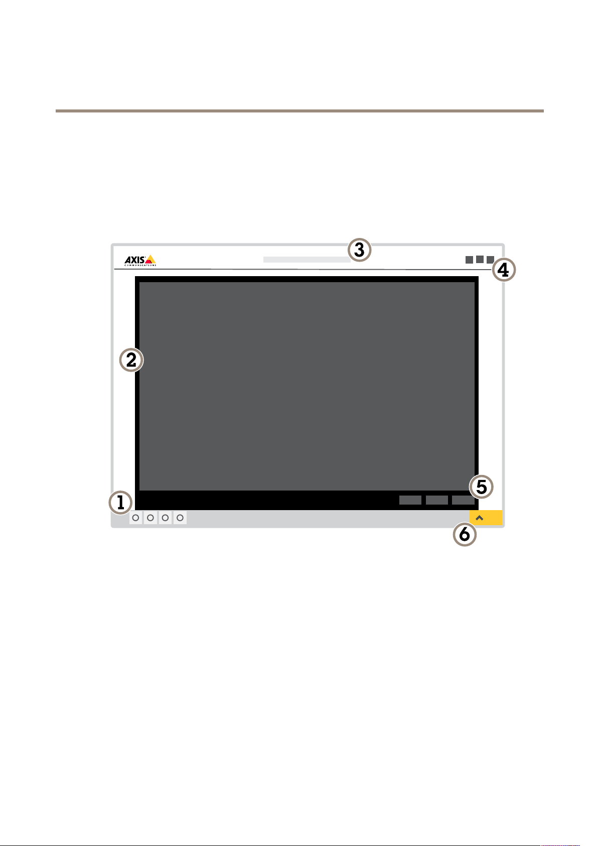
Webpage overview
1
Live view control bar
2
Live view
3
Product name
4
User information, color themes, and help
5
Video control bar
6
Settings toggle
4
Page 5

AXIS Q1615 Mk III Network Camera
Get started
7
Settings tabs
5
Page 6

AXIS Q1615 Mk III Network Camera
Additional settings
Additional settings
Image quality
Capture modes
Capture mode denes the maximum frame rate available in the Axis product. Depending on which capture mode you select, you
may not be able to use WDR.
A capture mode consists of a resolution and the corresponding frame rate available in the product. The capture mode setting
affects the camera’s eld of view and aspect ratio.
The lower resolution capture mode is cropped out from the highest resolution.
The image shows how the eld of view and aspect ratio can change between two different capture modes.
Which capture mode to choose depends on the requirements of frame rate and resolution for the specic surveillance setup. For
specications about available capture modes, see the product’s datasheet at axis.com.
Replace the lens
1. Stop all recordings and disconnect power from the product.
2. Disconnect the lens cable and remove the standard lens.
3. Attach the new lens and connect the lens cable.
4. Reconnect the power.
5. Log in to the product’s webpage, go to the Image tab and then select the P-Iris lens you have installed.
Note
If you use a DC iris lens, select Generic DC Iris.
6. For the changes to take effect, you need to restart the device. Go to System > Maintenance and click Restart.
7. Adjust the zoom and focus.
Select exposure mode
There are different exposure mode options in the camera that adjusts aperture, shutter speed, and gain to improve image quality for
specic surveillance scenes. Go to Settings > Image > Exposure and select between the following exposure modes:
6
Page 7

AXIS Q1615 Mk III Network Camera
Additional settings
• For most use cases, select Automatic exposure.
• For environments with certain articial lighting, for example uorescent lighting, select Flicker-free.
Select the same frequency as the power line frequency.
• For environments with certain articial light and bright light, for example outdoors with uorescent lighting at night and
sun during daytime, select Flicker-reduced.
Select the same frequency as the power line frequency.
• To lock the current exposure settings, select Hold current.
Reduce noise in low-light conditions
To reduce noise in low-light conditions, you can adjust one or more of the following settings:
• Adjust the trade-off between noise and motion blur. Go to Settings > Image > Exposure and move the Blur-noise
trade-off slider toward Low noise.
• Set the exposure mode to automatic.
Note
A high max shutter value can result in motion blur.
• To slow down the shutter speed, set max shutter to the highest possible value.
• Reduce sharpness in the image.
Note
When you reduce the max gain, the image can become darker.
• Set the max gain to a lower value.
• Open the aperture.
Reduce motion blur in low-light conditions
To reduce motion blur in low-light conditions, adjust one or more of the following settings in Settings > Image > Exposure:
• Move the Blur-noise trade-off slider toward Low motion blur.
Note
When you increase the gain, image noise also increases.
• Set Max shutter to a shorter time, and Max gain to a higher value.
Note
When you open the aperture, the depth of eld gets shallower.
• Move the Target aperture slider toward Open.
If you still have problems with motion blur:
• Increase the light level in the scene.
• Mount the camera so that objects move toward it or away from it rather than sideways.
Note
If you use a lens with a larger aperture, the depth of eld gets shallower.
7
Page 8

AXIS Q1615 Mk III Network Camera
Additional settings
• Change to a lens with a larger aperture.
Maximize details in an image
Important
If you maximize details in an image, the bitrate will probably increase and you might get a reduced frame rate.
• Make sure to select the capture mode that has the highest resolution.
• Set the compression as low as possible.
• Select MJPEG streaming.
• Turn off Zipstream functionality.
Handle scenes with strong backlight
Dynamic range is the difference in light levels in an image. In some cases the difference between the darkest and the brightest
areas can be signicant. The result is often an image where either the dark or the bright areas are visible. Wide dynamic range
(WDR) makes both dark and bright areas of the image visible.
Image without WDR.
Image with WDR.
Note
WDR might cause artifacts in the image.
1. Go to Settings > Image > Wide dynamic range.
2. Turn on WDR.
3. If you still have problems, go to Exposure and adjust the Exposure zone to cover the area of interest.
Find out more about WDR and how to use it at axis.com/web-articles/wdr.
8
Page 9
AXIS Q1615 Mk III Network Camera
Additional settings
Stabilize a shaky image with Electronic Image Stabilization (EIS)
Electronic Image Stabilization (EIS) can be used in environments where the product is mounted in an exposed location and subject to
vibrations, for example, wind or passing trafc. Turn on EIS to get a smoother and steadier image without blur.
EIS also reduces the le size of the compressed image and lowers the bitrate of the video stream.
Note
When EIS is turned on the image is cropped slightly, lowering the maximum resolution.
1. Go to Settings > Image > Image correction.
2. Turn on EIS.
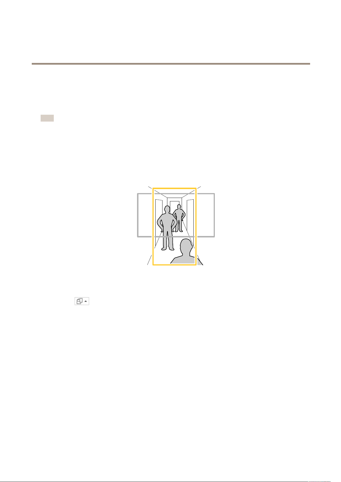
Monitor long and narrow areas
Use corridor format to better utilize the full eld of view in a long and narrow area, for example a staircase, hallway, road, or tunnel.
1. Depending on your device, turn the camera or the 3-axis lens in the camera 90° or 270°.
2. If the device doesn’t have automatic rotation of the view, log in to the webpage and go to Settings > System > Orientation.
3. Click
4. Rotate the view 90° or 270°.
Find out more at axis.com/axis-corridor-format.
.
Improve facial recognition
To better recognize the face of a person passing by the camera, you can set the optimal pixel resolution with the camera’s pixel
counter.
9
Page 10

AXIS Q1615 Mk III Network Camera
Additional settings
1. Go to Settings > System > Orientation and click .
2. In the camera’s live view, adjust the size and placement of the rectangle around the area of interest, for example, where
the faces of passing persons are expected to appear. You can then see the number of pixels represented by the sides of
the rectangle.
Note
You can use an object of a known size in the view as a reference to decide how much resolution is needed for recognition.
View area
A view area is a cropped part of the full view. You can stream and store view areas instead of the full view to minimize bandwidth
and storage needs. If you enable PTZ for a view area, you can pan, tilt and zoom within it. By using view areas you can remove parts
of the full view, for example, the sky.
When you set up a view area, we recommend you to set the video stream resolution to the same size as or smaller than the view area
size. If you set the video stream resolution larger than the view area size it implies digitally scaled up video after sensor capture,
which requires more bandwidth without adding image information.
Pan, tilt, and zoom (PTZ)
Guard tours
A guard tour displays the video stream from different preset positions either in a predetermined or random order, and for congurable
periods of time. Once started, a guard tour continues to run until stopped, even when there are no clients (web browsers) viewing the
images.
Create a guard tour with preset positions
A guard tour displays the video stream from different preset positions either in a predetermined or random order, and for congurable
periods of time.
1. Go to Settings > PTZ > Guard tours.
2. Click +.
3. To edit the guard tour’s properties, click
4. Type a name for the guard tour and specify the pause length in minutes between each tour.
5. If you want the guard tour to go to the preset positions in a random order, turn on Shufe.
.
10
Page 11

AXIS Q1615 Mk III Network Camera
Additional settings
6. Click Done.
7. Click Add to add the preset positions that you want in your guard tour.
8. Click Done to exit the guard tour settings.
9. To schedule the guard tour, go to System > Events.
Privacy masks
A privacy mask is a user-dened area that prevents users from viewing a part of the monitored area. In the video stream, privacy
masks appear as blocks of solid color or blurred image elements.
You’ll see the privacy mask on all snapshots, recorded video, and live streams.
You can use the VAPIX® application programming interface (API) to turn off the privacy masks.
Important
If you use multiple privacy masks it may affect the product’s performance.
Hide parts of the image with privacy masks
You can create one or several privacy masks to hide parts of the image.
1. Go to Settings > Privacy mask.
2. Click New.
3. Adjust the size, color, and name of the privacy mask according to your needs.
Overlays
Overlays are superimposed over the video stream. They are used to provide extra information during recordings, such as a timestamp,
or during product installation and conguration. You can add either text or an image.
Show a text overlay in the video stream when the device detects motion
This example explains how to display the text “Motion detected” when the device detects motion:
Make sure that AXIS Video Motion Detection is running:
1. Go to Settings > Apps > AXIS Video Motion Detection.
2. Start the application if it is not already running.
3. Make sure you have set up the application according to your needs.
Add the overlay text:
4. Go to Settings > Overlay.
5. Enter #D in the text eld.
6. Choose text size and appearance.
Create a rule:
7. Go to System > Events > Rules and add a rule.
8. Type a name for the rule.
9. In the list of conditions, select AXIS Video Motion Detection.
11
Page 12

AXIS Q1615 Mk III Network Camera
Additional settings
10. In the list of actions, select Use overlay text.
11. Select a view area.
12. Type “Motion detected”.
13. Set the duration.
14. Click Save.
Streaming and storage
Video compression formats
Decide which compression method to use based on your viewing requirements, and on the properties of your network. The
available options are:
Motion JPEG
Note
To ensure support for the Opus audio codec, the Motion JPEG stream is always sent over RTP.
Motion JPEG, or MJPEG, is a digital video sequence that is made up of a series of individual JPEG images. These images are then
displayed and updated at a rate sufcient to create a stream that shows constantly updated motion. For the viewer to perceive motion
video the rate must be at least 16 image frames per second. Full motion video is perceived at 30 (NTSC) or 25 (PAL) frames per second.
The Motion JPEG stream uses considerable amounts of bandwidth, but provides excellent image quality and access to every image
contained in the stream.
H.264 or MPEG-4 Part 10/AVC
Note
H.264 is a licensed technology. The Axis product includes one H.264 viewing client license. To install additional unlicensed
copies of the client is prohibited. To purchase additional licenses, contact your Axis reseller.
H.264 can, without compromising image quality, reduce the size of a digital video le by more than 80% compared to the Motion
JPEG format and by as much as 50% compared to the MPEG-4 standard. This means that less network bandwidth and storage space
are required for a video le. Or seen another way, higher video quality can be achieved for a given bitrate.
Reduce bandwidth and storage
Important
If you reduce the bandwidth it can result in loss of details in the picture.
1. Go to live view and select H.264.
2. Go to Settings > Stream.
3. Do one or more of the following:
- Turn on the Zipstream functionality and select the desired level.
- Turn on dynamic GOP and set a high GOP length value.
- Increase the compression.
- Turn on dynamic FPS.
12
Page 13

AXIS Q1615 Mk III Network Camera
Additional settings
Bitrate control
With bitrate control, you can manage the bandwidth consumption of your video stream.
Variable bitrate (VBR)
With variable bitrate, the bandwidth consumption varies based on the level of activity in the scene. The more activity in the scene,
the more bandwidth you need. You are guaranteed constant image quality but it requires storage margins.
Maximum bitrate (MBR)
With maximum bitrate, you can set a target bitrate to handle bitrate limitations in your system. You may see a decline in image
quality or frame rate when the instantaneous bitrate is kept below the specied target bitrate. You can choose to either prioritize
image quality or frame rate. We recommend that you congure the target bitrate to a higher value than the expected bitrate. This
gives you a margin for additional complexity that needs to be captured.
1
Target bitrate
Average bitrate (ABR)
With average bitrate, the bitrate is automatically adjusted over a longer timescale. This is so you can meet the specied target and
provide the best video quality based on your available storage. Bitrate is higher in scenes with a lot of activity, compared to static
scenes. You are more likely to get better image quality when needed when using the average bitrate option. You can dene the total
storage required to store the video stream for a specied amount of time (retention time) when image quality is adjusted to meet the
specied target bitrate. Specify the average bitrate settings in one of the following ways:
• To calculate the estimated storage need, set the target bitrate and the retention time.
• To calculate the average bitrate, based on available storage and required retention time, use the target bitrate calculator.
13
Page 14

AXIS Q1615 Mk III Network Camera
kbit/s
s
1
2
kbit/s
s
1
2
Additional settings
1
Target bitrate
2
Actual average bitrate
You can also turn on maximum bitrate and specify a target bitrate within the average bitrate option.
1
Target bitrate
2
Actual average bitrate
Set up network storage
To store recordings on the network, you need to set up network storage:
1. Go to Settings > System > Storage.
2. Click Setup under Network storage.
3. Enter the IP address of the host server.
4. Enter the name of the shared location on the host server.
5. Move the switch if the share requires a login, and enter username and password.
6. Click Connect.
Add audio to your recording
Turn on audio:
1. Go to Settings > Audio and turn on Allow audio.
2. Go to Input > Type and select your audio source.
14
Page 15

AXIS Q1615 Mk III Network Camera
Additional settings
Edit the stream prole which is used for the recording:
3. Go to Settings > Stream and click Stream proles.
4. Select the stream prole and click Audio.
5. Select the checkbox and select Include.
6. Click Save.
7. Click Close.
Events
Set up rules and alerts
You can create rules to make your device perform an action when certain events occur. A rule consists of conditions and actions.
The conditions can be used to trigger the actions. For example, the device can start a recording or send an email when it detects
motion, or show an overlay text when it records.
Trigger an action
1. Go to Settings > System > Events to set up a rule. The rule denes when the device will perform certain actions. Rules
can be setup as scheduled, recurring, or for example, triggered by motion detection.
2. Select the Condition that must be met to trigger the action. If you specify more than one condition for the rule, all of the
conditions must be met to trigger the action.
3. Select which Action the device should perform when the conditions are met.
Note
If you make changes to an active rule, then the rule needs to be restarted for the changes to take effect.
Note
If you change the denition of a stream prole that is used in a rule, then you need to restart all the rules that use that
stream prole.
Trigger an alarm if someone opens the housing
This example explains how to trigger an alarm if someone opens the housing.
Create a rule:
1. Go to Settings > System > Events and add a rule.
2. Type a name for the rule.
3. In the list of conditions, select Casing open.
4. In the list of actions, select Send notication to email.
5. Select a recipient from the list or go to Recipients to create a new recipient.
To create a new recipient, click
6. Type a subject and a message for the email.
7. Click Save.
. To copy an existing recipient, click .
15
Page 16

AXIS Q1615 Mk III Network Camera
Additional settings
Record video when the camera detects motion
This example explains how to set up the camera to start recording to the SD card ve seconds before it detects motion and to
stop one minute after.
Make sure that AXIS Video Motion Detection is running:
1. Go to Settings > Apps > AXIS Video Motion Detection.
2. Start the application if it is not already running.
3. Make sure you have set up the application according to your needs.
Create a rule:
1. Go to Settings > System > Events and add a rule.
2. Type a name for the rule.
3. In the list of conditions, under Application, select AXIS Video Motion Detection (VMD).
4. In the list of actions, under Recordings, select Record video while the rule is active.
5. Select an existing stream prole or create a new one.
6. Set the prebuffer time to 5 seconds.
7. Set the postbuffer time to 60 seconds.
8. In the list of storage options, select SD card.
9. Click Save.
Applications
AXIS Camera Application Platform (ACAP) is an open platform that enables third parties to develop analytics and other applications
for Axis products. To nd out more about available applications, downloads, trials and licenses, go to axis.com/applications.
To nd the user manuals for Axis applications, go to axis.com.
Note
• Several applications can run at the same time but some applications might not be compatible with each other. Certain
combinations of applications might require too much processing power or memory resources when run in parallel. Verify
that the applications work together before deployment.
16
Page 17

AXIS Q1615 Mk III Network Camera
Troubleshooting
Troubleshooting
If you can’t nd what you’re looking for here, try the troubleshooting section at axis.com/support.
Reset to factory default settings
Important
Reset to factory default should be used with caution. A reset to factory default resets all settings, including the IP address, to
the factory default values.
To reset the product to the factory default settings:
1. Disconnect power from the product.
2. Press and hold the control button while reconnecting power. See Product overview on page 22.
3. Keep the control button pressed for 15–30 seconds until the status LED indicator ashes amber.
4. Release the control button. The process is complete when the status LED indicator turns green. The product has been reset
to the factory default settings. If no DHCP server is available on the network, the default IP address is 192.168.0.90.
5. Use the installation and management software tools to assign an IP address, set the password, and access the video stream.
The installation and management software tools are available from the support pages on axis.com/support.
It is also possible to reset parameters to factory default through the web interface. Go to Settings > System > Maintenance and
click Default.
Check the current rmware
Firmware is the software that determines the functionality of network devices. One of your rst actions when troubleshooting a
problem should be to check the current rmware version. The latest version may contain a correction that xes your particular
problem.
To check the current rmware:
1. Go to the product’s webpage.
2. Click on the help menu
3. Click About.
.
Upgrade the rmware
Important
Precongured and customized settings are saved when the rmware is upgraded (provided that the features are available in
the new rmware) although this is not guaranteed by Axis Communications AB.
Important
Make sure the product remains connected to the power source throughout the upgrade process.
Note
When you upgrade the product with the latest rmware in the active track, the product receives the latest functionality
available. Always read the upgrade instructions and release notes available with each new release before upgrading the
rmware. To nd the latest rmware and the release notes, go to axis.com/support/rmware.
17
Page 18

AXIS Q1615 Mk III Network Camera
Troubleshooting
1. Download the rmware le to your computer, available free of charge at axis.com/support/rmware.
2. Log in to the product as an administrator.
3. Go to Settings > System > Maintenance. Follow the instructions on the page. When the upgrade has nished, the
product restarts automatically.
AXIS Device Manager can be used for multiple upgrades. Find out more at axis.com/products/axis-device-manager.
Technical issues, clues and solutions
If you can’t nd what you’re looking for here, try the troubleshooting section at axis.com/support.
Problems upgrading the rmware
Firmware upgrade failure If the rmware upgrade fails, the device reloads the previous rmware. The most common reason
Problems setting the IP address
The device is located on a
different subnet
The IP address is being used
by another device
is that the wrong rmware le has been uploaded. Check that the name of the rmware le
corresponds to your device and try again.
If the IP address intended for the device and the IP address of the computer used to access the
device are located on different subnets, you cannot set the IP address. Contact your network
administrator to obtain an IP address.
Disconnect the Axis device from the network. Run the ping command (in a Command/DOS window,
type ping and the IP address of the device):
• If you receive: Reply from <IP address>: bytes=32; time=10...
this means that the IP address may already be in use by another device on the network.
Obtain a new IP address from the network administrator and reinstall the device.
• If you receive: Request timed out, this means that the IP address is available
for use with the Axis device. Check all cabling and reinstall the device.
Possible IP address conict
with another device on the
same subnet
The device cannot be accessed from a browser
Cannot log in
The IP address has been
changed by DHCP
Certicate error when using
IEEE 802.1X
The device is accessible locally but not externally
To access the device externally, we recommend using one of the following applications for Windows®:
The static IP address in the Axis device is used before the DHCP server sets a dynamic address.
This means that if the same default static IP address is also used by another device, there may
be problems accessing the device.
When HTTPS is enabled, ensure that the correct protocol (HTTP or HTTPS) is used when attempting
to log in. You may need to manually type http or https in the browser’s address eld.
If the password for the user root is lost, the device must be reset to the factory default settings.
See Reset to factory default settings on page 17.
IP addresses obtained from a DHCP server are dynamic and may change. If the IP address has been
changed, use AXIS IP Utility or AXIS Device Manager to locate the device on the network. Identify
the device using its model or serial number, or by the DNS name (if the name has been congured).
If required, a static IP address can be assigned manually. For instructions, go to axis.com/support.
For authentication to work properly, the date and time settings in the Axis device must be
synchronized with an NTP server. Go to Settings > System > Date and time.
• AXIS Companion: free of charge, ideal for small systems with basic surveillance needs.
• AXIS Camera Station: 30-day trial version free of charge, ideal for small to mid-size systems.
For instructions and download, go to axis.com/vms.
18
Page 19

AXIS Q1615 Mk III Network Camera
Troubleshooting
Problems with streaming
Multicast H.264 only
accessible by local clients
No multicast H.264
displayed in the client
Poor rendering of H.264
images
Color saturation is different
in H.264 and Motion JPEG
Lower frame rate than
expected
Check if your router supports multicasting, or if the router settings between the client and the
device need to be congured. The TTL (Time To Live) value may need to be increased.
Check with your network administrator that the multicast addresses used by the Axis device
are valid for your network.
Check with your network administrator to see if there is a rewall preventing viewing.
Ensure that your graphics card is using the latest driver. The latest drivers can usually be
downloaded from the manufacturer’s website.
Modify the settings for your graphics adapter. Go to the adapter’s documentation for more
information.
• See Performance considerations on page 19.
• Reduce the number of applications running on the client computer.
• Limit the number of simultaneous viewers.
• Check with the network administrator that there is enough bandwidth available.
• Lower the image resolution.
• Log in to the device’s webpage and set a capture mode that prioritizes frame rate.
Changing the capture mode to prioritize frame rate might lower the maximum
resolution depending on the device used and capture modes available.
• The maximum frames per second is dependent on the utility frequency (60/50 Hz)
of the Axis device.
Performance considerations
When setting up your system, it is important to consider how various settings and situations affect the performance. Some factors
affect the amount of bandwidth (the bitrate) required, others can affect the frame rate, and some affect both. If the load on the
CPU reaches its maximum, this also affects the frame rate.
The following factors are the most important to consider:
• High image resolution or lower compression levels result in images containing more data which in turn affects the
bandwidth.
• Rotating the image in the GUI will increase the product's CPU load.
• Access by large numbers of Motion JPEG or unicast H.264 clients affects the bandwidth.
• Simultaneous viewing of different streams (resolution, compression) by different clients affects both frame rate and
bandwidth.
Use identical streams wherever possible to maintain a high frame rate. Stream proles can be used to ensure that
streams are identical.
• Accessing Motion JPEG and H.264 video streams simultaneously affects both frame rate and bandwidth.
• Heavy usage of event settings affects the product’s CPU load which in turn affects the frame rate.
• Using HTTPS may reduce frame rate, in particular if streaming Motion JPEG.
• Heavy network utilization due to poor infrastructure affects the bandwidth.
• Viewing on poorly performing client computers lowers perceived performance and affects frame rate.
• Running multiple AXIS Camera Application Platform (ACAP) applications simultaneously may affect the frame rate and
the general performance.
19
Page 20

AXIS Q1615 Mk III Network Camera
Troubleshooting
Contact support
Contact support at axis.com/support.
20
Page 21

AXIS Q1615 Mk III Network Camera
Specifications
Specifications
To nd the latest version of the product’s datasheet, go to the product page at axis.com and locate Support & Documentation.
21
Page 22
AXIS Q1615 Mk III Network Camera
Specifications
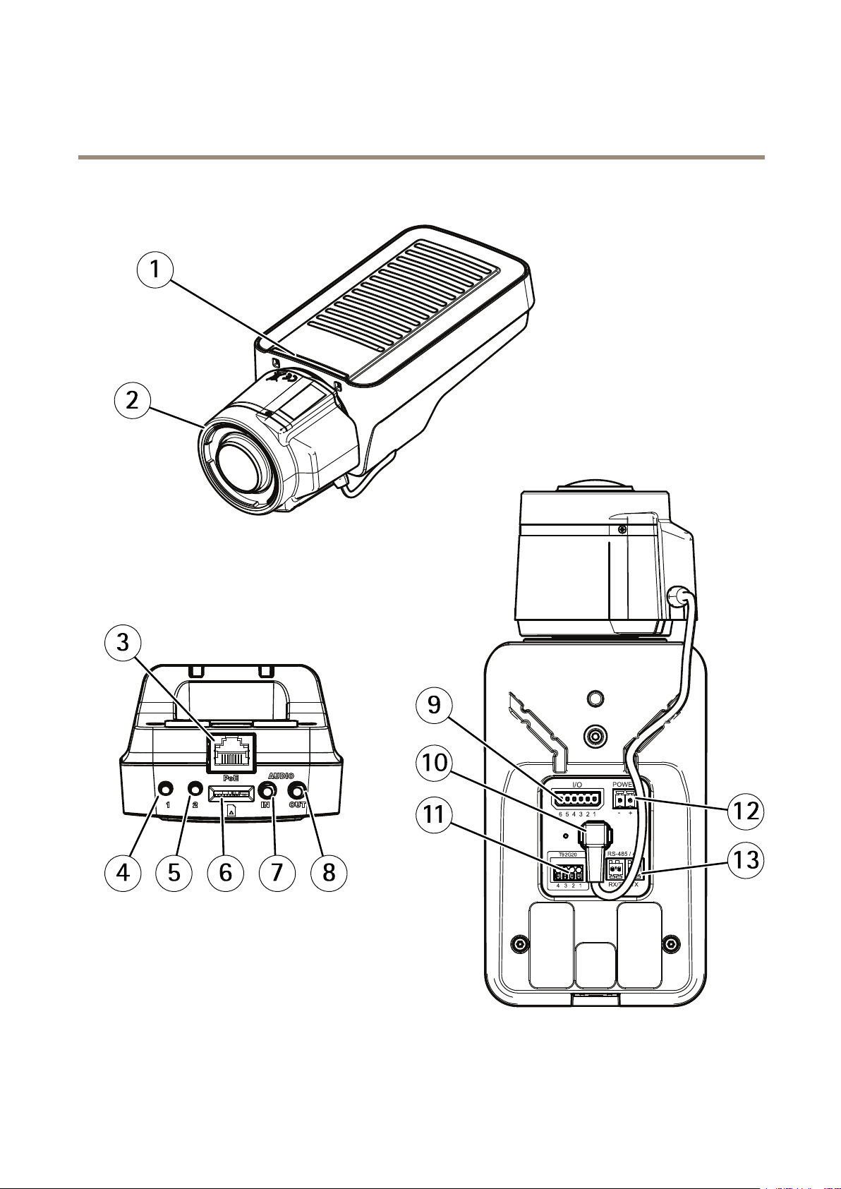
Product overview
1
Status LED indicator
2
Lens
3
Network connector (PoE)
22
Page 23

AXIS Q1615 Mk III Network Camera
Specifications
4
Control button (1)
5
Function button (2)
6
microSD Card slot
7
Audio in
8
Audio out
9
I/O connector
10
Iris connector
11
Camera housing communication connector
12
Power connector
13
RS485/RS422 connector
LED indicators
Note
The Status LED can be congured to ash while an event is active.
Status LED
Unlit
Green Shows steady green for 10 seconds for normal operation after startup completed.
Amber
Amber/Red Flashes amber/red if network connection is unavailable or lost.
Indication
Connection and normal operation.
Steady during startup. Flashes during rmware upgrade or reset to factory default.
Status LED behavior for focus assistant
Note
Only valid for optional P-iris, DC-iris or manual iris lenses.
The status LED ashes when the Focus Assistant is active.
Color
Red The image is out of focus.
Amber The image is close to focus.
Green
Buzzer signal for focus assistant
Note
Only valid for optional P-iris, DC-iris or manual iris lenses.
Indication
Adjust the lens.
The lens needs ne tuning.
The image is in focus.
Buzzer Lens
Fast interval
Medium interval Less optimally adjusted
Slow interval
Optimally adjusted
Poorly adjusted
Status LED behavior and buzzer signal for leveling assistant
For information on the function button used for leveling the camera, see page 24.
23
Page 24

AXIS Q1615 Mk III Network Camera
Specifications
Press and hold the function button (2) for more than two seconds to level the camera.
• When the camera is level, both LEDs are steady green, and the beep is continuous.
• When the camera is not level, the LEDs ash a combination of red, green and orange, and the beep occurs at slow intervals.
Both LEDs briey ash green to indicate that the leveling is getting better.
SD card slot
TICE
NONONOTICETICE
• Risk of damage to SD card. Do not use sharp tools, metal objects, or excessive force when inserting or removing the
SD card. Use your ngers to insert and remove the card.
• Risk of data loss and corrupted recordings. Do not remove the SD card while the product is running. Unmount the SD card
from the product’s webpage before removal.
This product supports microSD/microSDHC/microSDXC cards.
For SD card recommendations, see axis.com.
trademarks or registered trademarks of SD-3C, LLC in the United States, other countries or both.
microSD, microSDHC, and microSDXC Logos are trademarks of SD-3C LLC. microSD, microSDHC, microSDXC are
Buttons
Control button
The control button is used for:
• Resetting the product to factory default settings. See Reset to factory default settings on page 17.
Function button
Note
Focus assistant is only valid for optional P-iris, DC-iris or manual iris lenses.
Use the function button to activate the following functions:
Leveling assistant - This function helps to make sure the camera is level. To start the leveling assistant, press the button for about
3 seconds. Press again to stop the leveling assistant. The status LED and buzzer signal assist leveling of the camera, see Status LED
behavior and buzzer signal for leveling assistant on page 23. The camera is level when the buzzer beeps continuously.
Focus assistant - This function is used for enabling the focus assistant. To enable the focus assistant, press and very quickly release
the button. Press again to stop the focus assistant. To nd out more, see the Installation Guide.
Connectors
Network connector
RJ45 Ethernet connector with Power over Ethernet (PoE).
Audio connector
• Audio in – 3.5 mm input for a mono microphone, or a line-in mono signal (left channel is used from a stereo signal).
24
Page 25
AXIS Q1615 Mk III Network Camera
Specifications
• Audio out – 3.5 mm output for audio (line level) that can be connected to a public address (PA) system or an active
speaker with a built-in amplier. A stereo connector must be used for audio out.
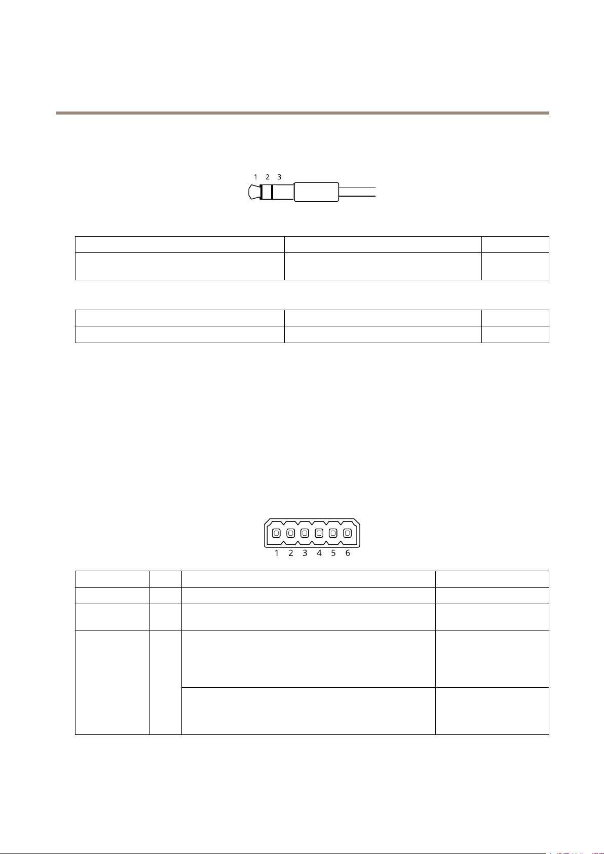
Audio input
1 Tip 2 Ring
Balanced microphone (with or without phantom power)
or line, “hot” signal
Audio output
1 Tip 2 Ring
Channel 1, unbalanced line, mono Channel 1, unbalanced line, mono Ground
Balanced microphone (with or without phantom
power) or line, “cold” signal
3 Sleeve
Ground
3 Sleeve
I/O connector
Use the I/O connector with external devices in combination with, for example, motion detection, event triggering, and alarm
notications. In addition to the 0 V DC reference point and power (DC output), the I/O connector provides the interface to:
Digital input - For connecting devices that can toggle between an open and closed circuit, for example PIR sensors, door/window
contacts, and glass break detectors.
Supervised input - Enables possibility to detect tampering on a digital input.
Digital output - For connecting external devices such as relays and LEDs. Connected devices can be activated by the VAPIX®
Application Programming Interface or from the product’s webpage.
6-pin terminal block
Function Pin Notes
DC ground
DC output
Congurable
(Input or Output)
Example
1
2
3–6
Can be used to power auxiliary equipment.
Note: This pin can only be used as power out.
Digital input – Connect to pin 1 to activate, or leave oating
(unconnected) to deactivate.
Pin 3 and 4 can be supervised. To use supervised input, install
end-of-line resistors. See connection diagram for information about
how to connect the resistors.
Digital output – Internally connected to pin 1 (DC ground) when
active, and oating (unconnected) when inactive. If used with an
inductive load, e.g., a relay, connect a diode in parallel with the load,
to protect against voltage transients.
Specications
0 V DC
12 V DC
Max load = 50 mA
0 to max 30 V DC
0 to max 30 V DC, open drain,
100 mA
25
Page 26

AXIS Q1615 Mk III Network Camera
Specifications
1
DC ground
2
DC output 12 V, max 50 mA
3
I/O congured as supervised input
4
I/O congured as output
5
Congurable I/O
6
Congurable I/O
Power connector
2-pin terminal block for DC power input. Use a Safety Extra Low Voltage (SELV) compliant limited power source (LPS) with either
a rated output power limited to ≤100 W or a rated output current limited to ≤5 A.
RS485/RS422 connector
Two 2-pin terminal blocks for RS485/RS422 serial interface used to control auxiliary equipment such as pan-tilt devices.
The serial port can be congured to support:
• Two-wire RS485 half duplex
• Four-wire RS485 full duplex
• Two-wire RS422 simplex
• Four-wire RS422 full duplex point to point communication
26
Page 27

AXIS Q1615 Mk III Network Camera
Specifications
Function Pin Notes
RS485B alt RS485/422 RX(B)
RS485A alt RS485/422 RX(A)
RS485/RS422 TX(B)
RS485/RS422 TX(A)
Important
The maximum cable length is 30 m (98 ft).
1
2
3
4
RX pair for all modes (combined RX/TX for 2-wire RS485)
TX pair for RS422 and 4-wire RS485
27
Page 28

User Manual Ver. M2.6
AXIS Q1615 Mk III Network Camera
© Axis Communications AB, 2020
Date: July 2020
Part No. T10153024
 Loading...