

Axis PT IR Illuminator Kit A Installation Manual

INSTALLATION GUIDE
ENGLISH FRANÇAIS DEUTSCH ITALIANO ESPAÑOL
PT IR Illuminator Kit A
Safety
This product complies with EN/IEC 60950-1 and EN/IEC
60950-22, Safety of Information Technology Equipment.
Photobiological Safety
This product fulfills the requirements for photobiological safety
according to EN 62471 (risk group 1).
Equipment Modifications
This equipment must be installed and used in strict accordance
with the instructions given in the user documentation. This
equipment contains no user-serviceable components.
Unauthorized equipment changes or modifications will invalidate
all applicable regulatory certifications and approvals.
Electromagnetic Compatibility (EMC)
See AXIS Q87-E Dual PTZ Network Camera Series Installation
Guide.
Liability
Every care has been taken in the preparation of this document.
Please inform your local Axis office of any inaccuracies or
omissions. Axis Communications AB cannot be held responsible
for any technical or typographical errors and reserves the right to
make changes to the product and documentation without prior
notice. Axis Communications AB makes no warranty of any kind
with regard to the material contained within this document,
including, but not limited to, the implied warranties of
merchantability and fitness for a particular purpose. Axis
Communications AB shall not be liable nor responsible for
incidental or consequential damages in connection with the
furnishing, performance or use of this material. This product is
only to be used for its intended purpose.
RoHS
This product complies with both the European RoHS
directive, 2002/95/EC, and the Chinese RoHS regulations,
ACPEIP.
WEEE Directive
The European Union has enacted a Directive 2002/96/EC
on Waste Electrical and Electronic Equipment (WEEE
Directive). This directive is applicable in the European
Union member states.
The WEEE marking on this product (see right) or its
documentation indicates that the product must not be disposed of
together with household waste. To prevent possible harm to
human health and/or the environment, the product must be
disposed of in an approved and environmentally safe recycling
process. For further information on how to dispose of this product
correctly, contact the product supplier, or the local authority
responsible for waste disposal in your area.
Business users should contact the product supplier for information
on how to dispose of this product correctly. This product should
not be mixed with other commercial waste.
Support
Should you require any technical assistance, please contact your
Axis reseller. If your questions cannot be answered immediately,
your reseller will forward your queries through the appropriate
channels to ensure a rapid response. If you are connected to the
Internet, you can:
• download user documentation and firmware updates
• find answers to resolved problems in the FAQ database. Search
by product, category, or phrases
• report problems to Axis support by logging in to your private
support area
Contact Information
Axis Communications AB
Emdalavägen 14
223 69 Lund
Sweden
Tel: +46 46 272 18 00
Fax: +46 46 13 61 30
www.axis.com
ENGLISH
Safeguards
Please read through this Installation Guide carefully before installing the product. Keep the Installation Guide for
further reference.
• Store the Axis product in a dry and ventilated environment.
• Avoid exposing the Axis product to vibration, shocks or heavy pressure and do not install the product on
unstable brackets, unstable or vibrating surfaces or walls, since this could cause damage to the product.
• Only use applicable tools when installing the Axis product; excessive force could cause damage to the
product.
• Do not aim the thermal camera lens toward the sun or other high-intensity radiation sources since this
could cause damage to the sensor.
• Do not use chemicals, caustic agents, or aerosol cleaners. Use a damp cloth for cleaning.
• Only use accessories that comply with the technical specification of the product. These can be provided by
Axis or a third party.
• Use only spare parts provided by or recommended by Axis.
• Do not attempt to repair the product by yourself, contact Axis or your Axis reseller for service matters.
• This Axis product shall be used in compliance with local laws and regulations.
• The Axis product should be installed by a trained professional. Please observe relevant national and local
regulations for the installation.
Transportation
• When transporting the Axis product, use the original packaging or equivalent to prevent damage to the
product.

PT IR Illuminator Kit A Installation Guide Page 5
ENGLISH
PT IR Illuminator Kit A
Installation Guide
This Installation Guide provides instructions for installing PT IR Illuminator Kit A on AXIS Q87-E Dual PTZ Network
Camera Series.
Note: When installing the PT IR Illuminator Kit A together with the AXIS Q87-E Dual PTZ Network Camera
Series, start with the AXIS Q87-E Dual PTZ Network Camera Series Installation Guide.
Installation Steps
1. Check the package contents against the list below.
2. Hardware overview. See page 6.
3. Install the Illuminators. See page 7.
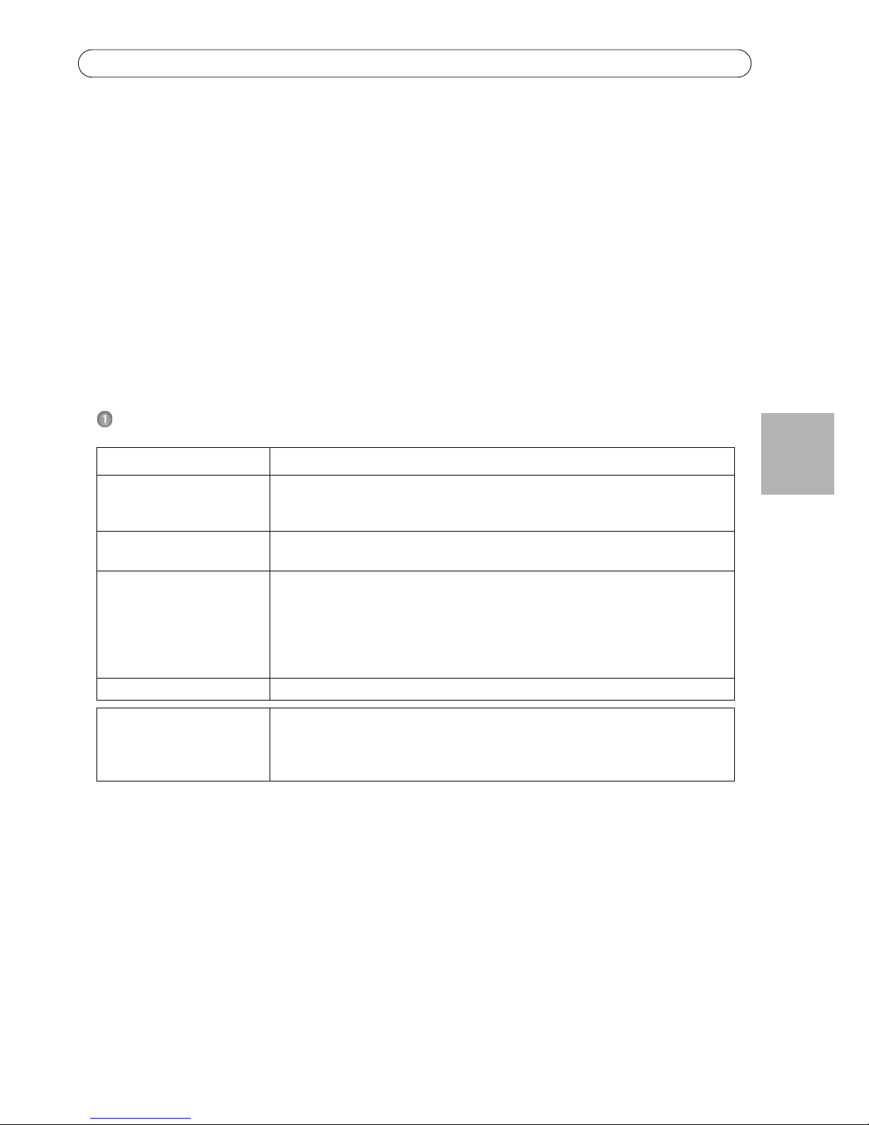
Package Contents
Item Models/variants/notes
Illuminators PT IR Illuminator Kit A: IR-LED 10° angle
IR-LED 50° angle
Built-in adjustable photocell
Brackets Crossbar
Illuminator bracket (2x)
Screw kit Crossbar screw (4x)
Illuminator bracket screw (4x)
Washer (8x)
Lock washer (10x)
Illuminator screw (2x)
Rubber shim (2x)
Printed materials PT IR Illuminator Kit A Installation Guide (this document)
Tools needed (not included) RJ45 crimp tool
Allen key set
Ratchet set
Loctite 243® threadlocker
Page 6 PT IR Illuminator Kit A Installation Guide
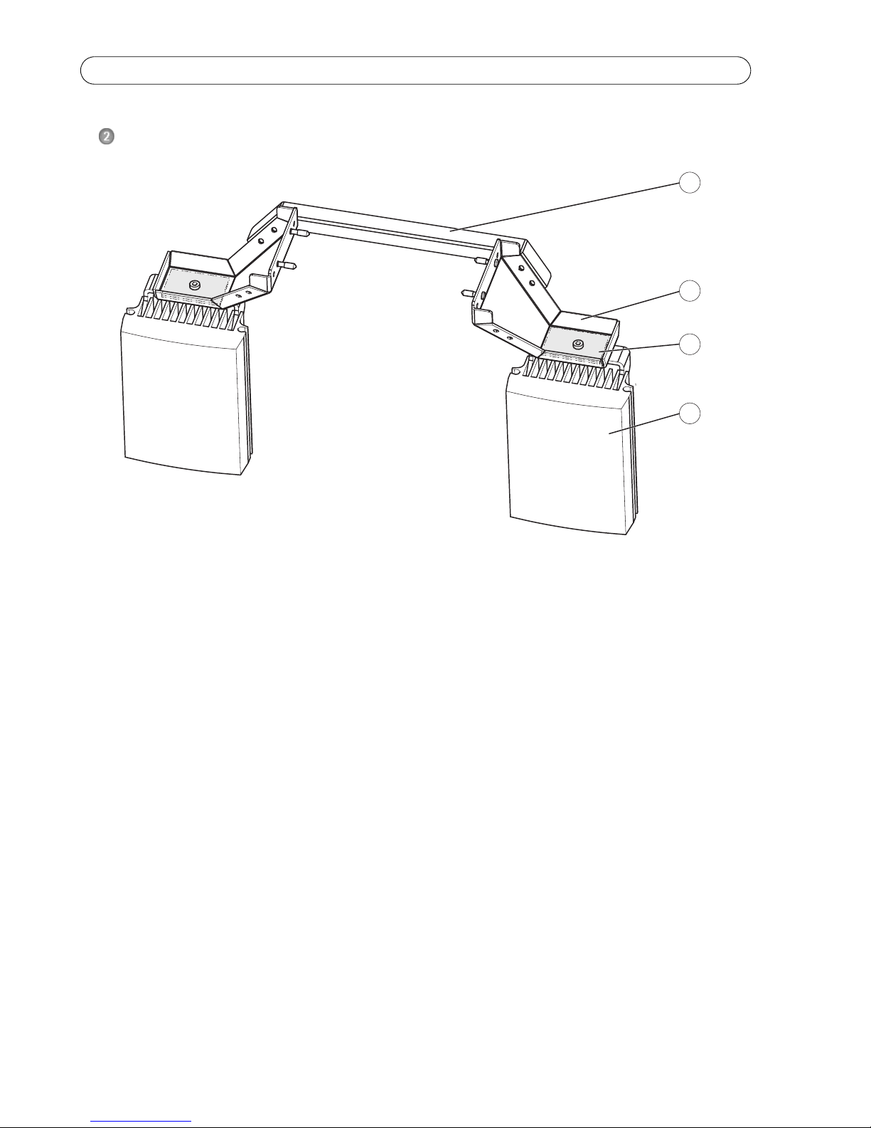
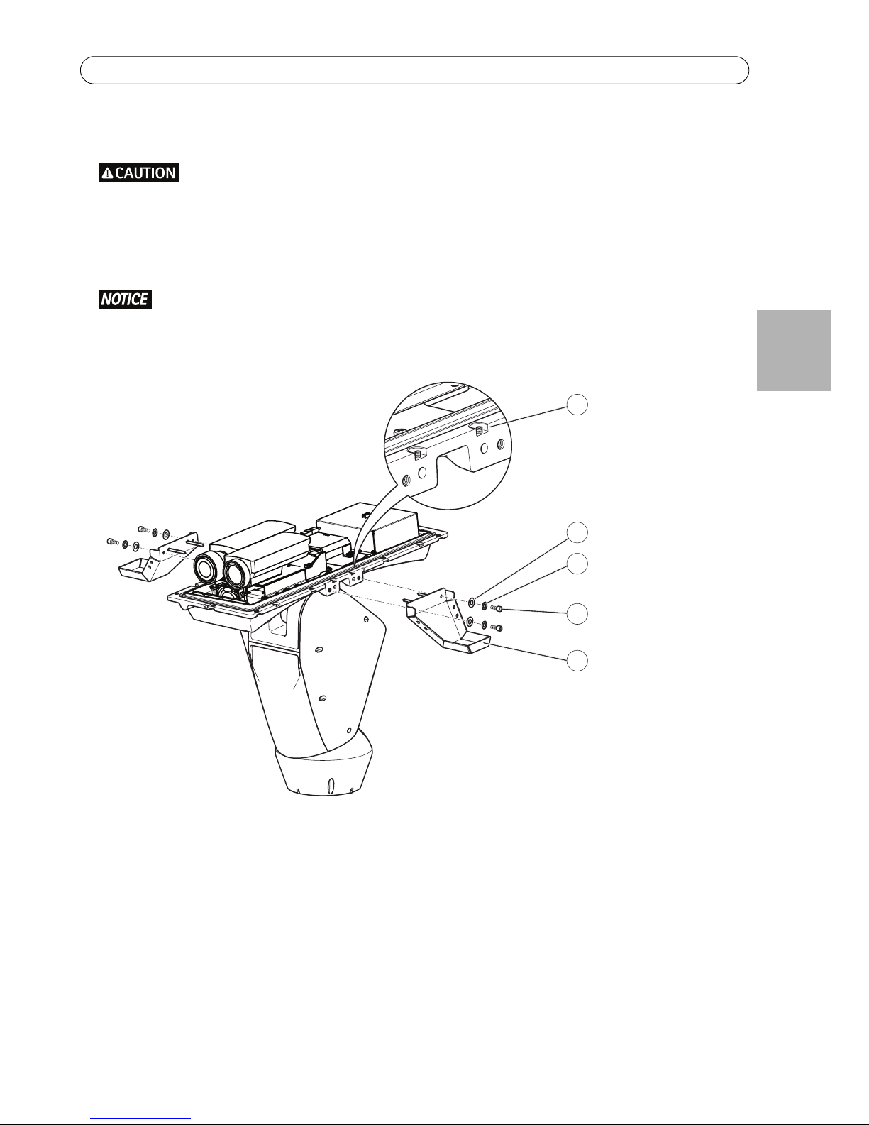
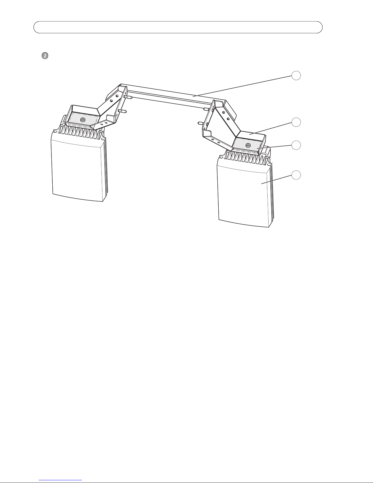
Hardware Overview
1
2
3
4
1 Crossbar
2 Illuminator bracket (2)
3 Rubber shim (2x)
4 Illuminator (2x)
PT IR Illuminator Kit A Installation Guide Page 7
ENGLISH
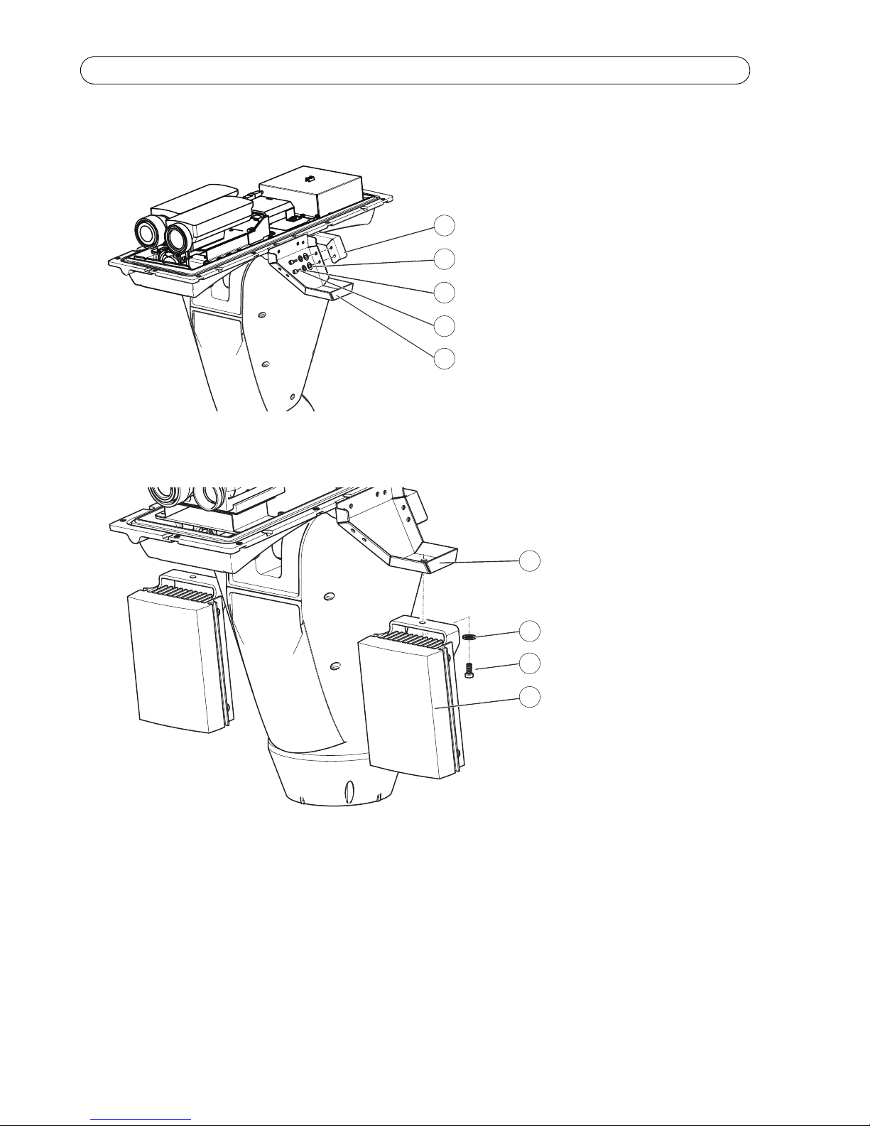
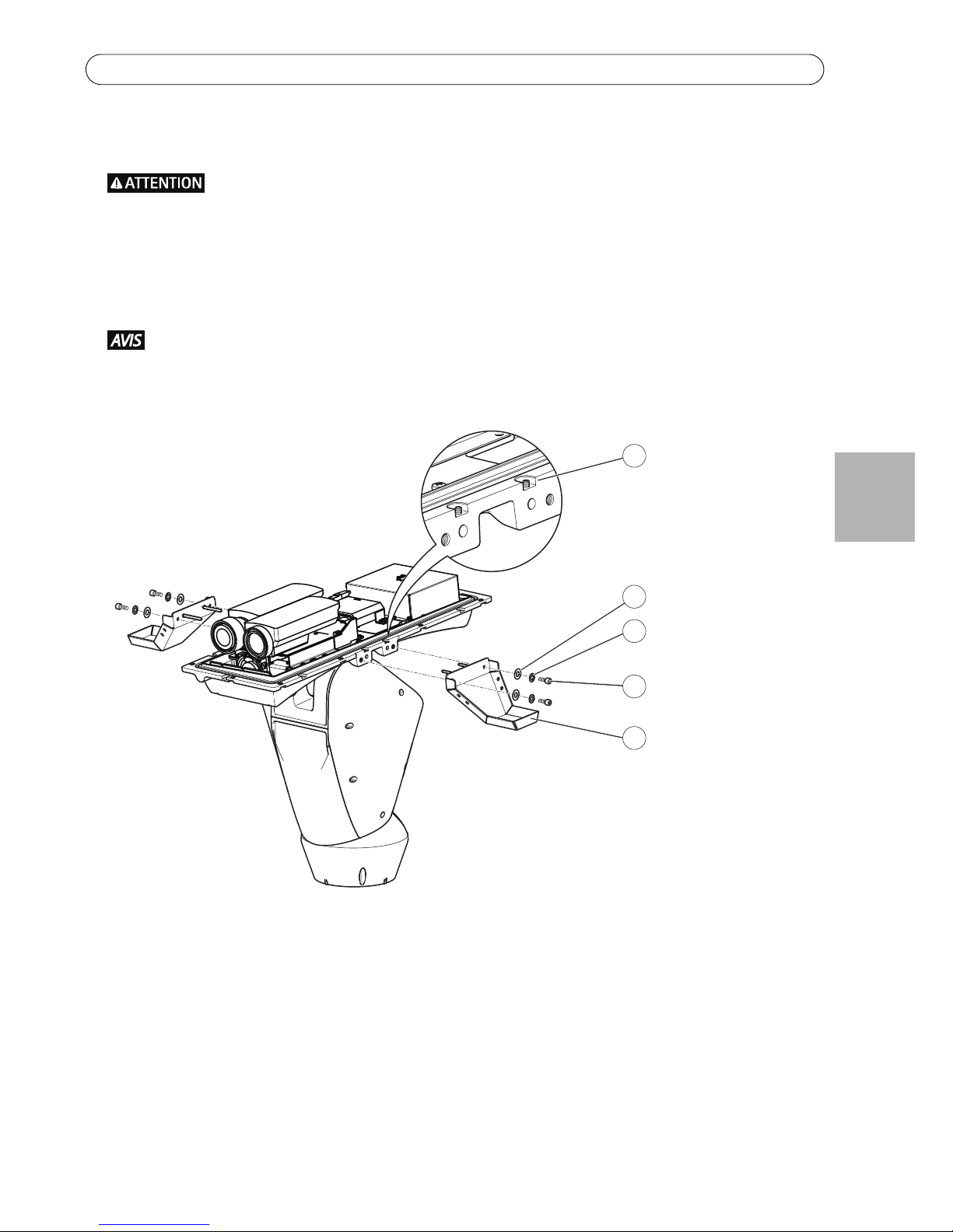
Install the Illuminators
IR light is emitted from this product (risk group 1). Use appropriate shielding or eye protection.
1. Unscrew the bottom cover screws and remove the top cover, see illustration on page 12.
2. Attach the illuminator brackets to the bottom cover using the supplied screws, lock washers and washers
(torque 4 Nm).
Apply Loctite 243
threadlocker on the screws.
3. Secure the illuminator brackets using the supplied grub screws (torque 4 Nm).
1
3
2
4
5
1Grub screw (4x)
2Washer (4x)
3Lock washer (4x)
4 Illuminator bracket screw (4x)
5 Illuminator bracket (2x)
Page 8 PT IR Illuminator Kit A Installation Guide
4. Attach the crossbar to the illuminator brackets using the supplied screws, washers and lock washers (torque
4Nm).
5. Attach the illuminators to the illuminator brackets using the supplied screws and washers (torque 4 Nm).
1
2
3
4
5
1 Crossbar
2Washer (4x)
3 Lock washer (4x)
4 Crossbar screws (4x)
5 Illuminator bracket (2x)
4
3
2
1
1 Illuminator bracket (2x)
2 Lock washer (2x)
3 Illuminator screw (2x)
4 Illuminator (2x)
PT IR Illuminator Kit A Installation Guide Page 9
ENGLISH
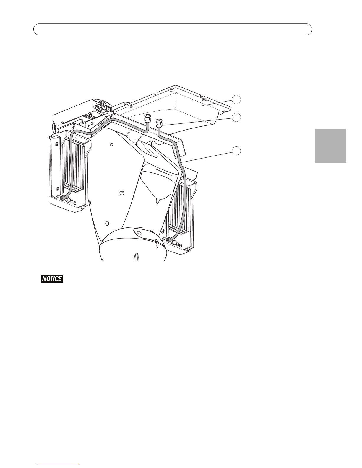
6. Route the illuminator cables along the illuminator bracket using cable ties.
7. Route the illuminator cables through the illuminator cable glands in the bottom cover and screw the caps on
firmly (torque 3 Nm).
Make sure the cables are properly grounded. The shield shall be in full contact with the metal cable gland.
2
1
3
1 Bottom cover
2 Cable gland and
cable gland cap (2x)
3 Illuminator cable (2x)
Page 10 PT IR Illuminator Kit A Installation Guide
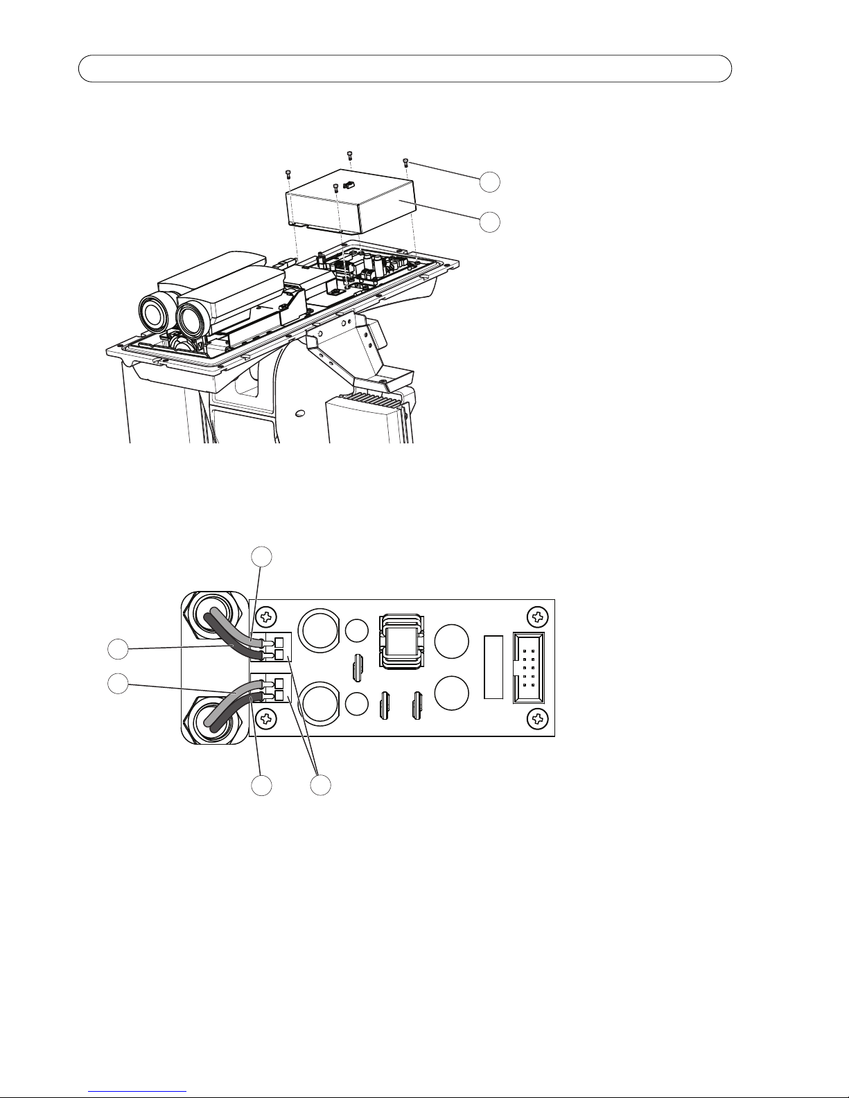
8. Remove the screws and the cover.
9. Connect the wires to the illuminator connectors.
10. Put the cover back and secure it with the screws.
11. Secure the illuminator cables using cable ties so that they do not get caught when the dual PTZ network
camera is moving.
1
2
1Screw (4x)
2Cover
2
3
1
3
2
1 Illuminator connector (2x)
2 Illuminator cables red (2x)
3 Illuminator cables black (2x)
PT IR Illuminator Kit A Installation Guide Page 11
ENGLISH
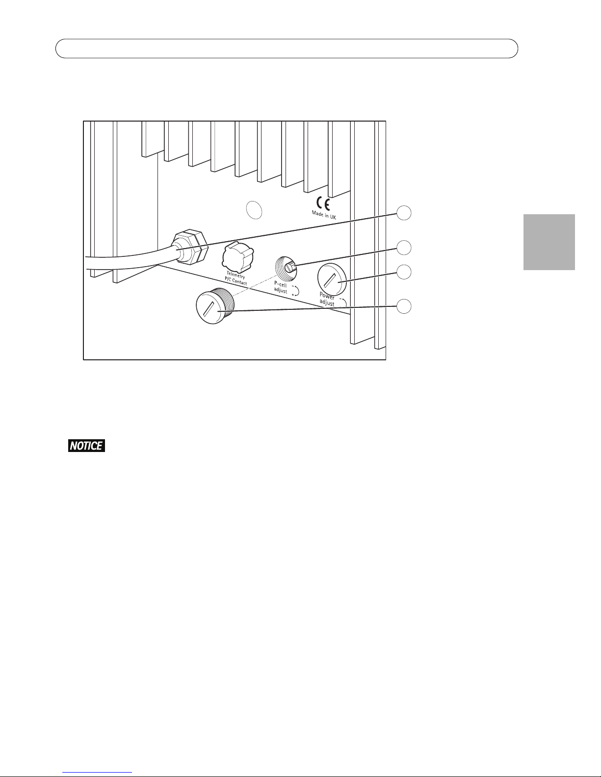
12. Make sure the photocell potentiometer on each Illuminator is turned to its maximum setting (+)
13. If required, turn the power potentiometer on each illuminator to adjust the light intensity.
14.Put the potentiometer caps back in their original places.
The potentiometer caps must be in place to maintain the product’s IP66 rating.
15. Attach the top cover to the bottom cover. Make sure to tighten diagonally opposite bottom cover screws a
few turns at a time until all are tight (torque 4 Nm). This will help ensure that the bottom cover gasket is
compressed evenly.
2
3
1
4
1 Illuminator cable (red, black) 3 Power potentiometer
2 Photocell potentiometer 4 Potentiometer cap (2x)
Page 12 PT IR Illuminator Kit A Installation Guide
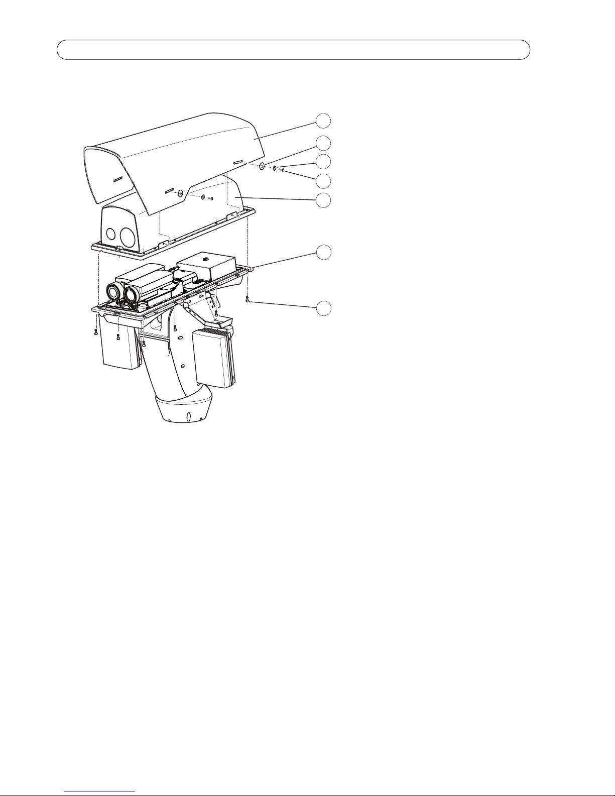
16. Attach the sunshield to the top cover.
1
2
3
7
4
5
6
1Sunshield
2Washer (4x)
3 Lock washer (4x)
4 Sunshield screw (4x)
5Top cover
6 Bottom cover
7 Bottom cover screw (8x)
PT IR Illuminator Kit A Installation Guide Page 13
ENGLISH
Technical Specifications
For technical specifications of the network cameras, see the respective User Manuals.
Further Information
Visit Axis learning center www.axis.com/academy for useful trainings, webinars, tutorials and guides.
Warranty
For information about Axis’ product warranty and thereto related information, see www.axis.com/warranty
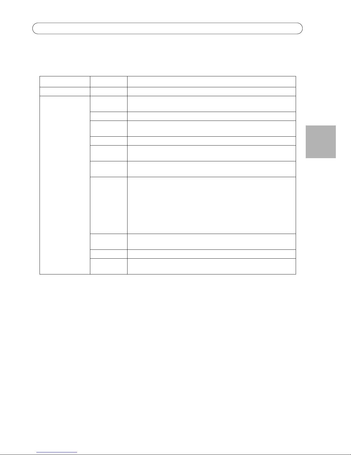
Function/group Item Specifications
IR Illuminators Models PT IR Illuminator Kit A: IR-LED 10° angle, IR-LED 50° angle
General Power 12 – 24 V AC/DC, 35 W
Cable length 2.5 m (8 ft.)
Type 850 nm semi-covert
Control
technology
Power level, photocell sensitivity, telemetry link for remote activation
(if required)
Angle 10° to 50°
Distance IR-LED 10°: 100 m (328 ft.)
IR-LED 50°: 50 m (164 ft.)
Operating
conditions
-50 °C to 50 °C (-58 °F to 122 °F)
Approvals EN 62471 (risk group 1)
EN 55022 Class A, EN 55024, EN 61000-6-1, EN 61000-6-2
FCC Part 15 Subpart B Class A demonstrated by compliance with EN
55022
ICES-003 Class A demonstrated by compliance with EN 55022
C-tick AS/NZS CISPR 22 demonstrated by compliance with EN 55022
EN 60950-1, EN 60950-22
IEC/EN 60529 IP66
Weight per
unit
1.4 kg (3.1 lb.)
Dimensions 180 x 135 x 67 mm (7” x 5.2” x 2.6”)
Included
accessories
U-bracket, built-in adjustable photocell

FRANÇAISFRANÇAIS
Mesures de sécurité
Lisez attentivement le présent Guide d'installation avant d'installer le produit Axis. Conservez le Guide
d'installation pour une utilisation ultérieure.
• Conservez le produit Axis dans un environnement sec et aéré.
• Évitez d'exposer le produit Axis aux vibrations, aux chocs ou à une forte pression. N'installez pas le produit
sur un support instable, ou des surfaces ou des murs instables ou vibrants, car cela pourrait l'endommager.
• N'utilisez que les outils applicables pour installer le produit Axis ; une force excessive pourrait endommager
le produit.
• Ne dirigez pas l'objectif de la caméra thermique vers le soleil ou d'autres sources de rayonnement à haute
intensité car cela pourrait endommager le capteur.
• Pour le nettoyage, n’utilisez ni produits chimiques, ni substances caustiques ou aérosols. Utilisez un chiffon
humide pour le nettoyage.
• N’utilisez que des accessoires conformes aux caractéristiques techniques du produit. Ceux-ci peuvent être
fournis par Axis ou par un fournisseur tiers.
• Utilisez uniquement des pièces de rechange fournies ou recommandées par Axis.
• Ne tentez pas de réparer le produit vous-même, contactez Axis ou votre revendeur Axis pour toute
réparation.
• Ce produit Axis doit être utilisé conformément aux lois et réglementations locales en vigueur.
• Le produit Axis doit être installé par un professionnel qualifié. Veuillez vous conformer aux règlements
nationaux et locaux relatifs à l'installation.
Transport
• Pour transporter le produit Axis et éviter de l'endommager, utilisez l'emballage d'origine ou un emballage
équivalent.

Kit PT Projecteur IR A Guide d’installation Page 17
FRANÇAIS
Kit PT Projecteur IR A
Guide d’installation
Ce Guide d'installation fournit des instructions pour l'installation du Kit PT Projecteur IR A sur la double caméra
réseau PTZ AXIS Q87.
Note : Lors de l'installation du Kit PT Projecteur IR A en combinaison avec la double caméra réseau
PTZ AXIS Q87, commencez par consulter le Guide d'installation de la double caméra réseau PTZ AXIS
Q87.
Procédures d’installation
1. Vérification du contenu du paquet par rapport à la liste ci-dessous.
2. Aperçu du matériel. Cf. page 18.
3. Installation du projecteur. Cf. page 19.
Contenu du paquet
Élément Modèles/variantes/remarques
Projecteur Kit PT Projecteur IR A: IR-DEL angle 10°
IR-DEL angle 50°
Photocellule réglable intégrée
Supports de fixation Barre transversale
Support du projecteur (2x)
Kit de visserie Vis de barre transversale (4x)
Vis de support du projecteur (4x)
Rondelle (8x)
Rondelle de blocage (10x)
Vis du projecteur (2x)
Cale en caoutchouc (2x)
Documentation imprimée Kit PT Projecteur IR A Guide d’installation (le présent document)
Outils nécessaires (non
inclus)
Pince à sertir RJ45
Jeu de clés Allen
Ensemble à cliquet
Frein filet Loctite 243®
Page 18 Kit PT Projecteur IR A Guide d'installation
Aperçu du matériel
1
2
3
4
1 Barre transversale
2 Support du projecteur (2x)
3 Cale en caoutchouc (2x)
4 Projecteur (2x)
Kit PT Projecteur IR A Guide d’installation Page 19
FRANÇAIS
Installation du projecteur
De la lumière infrarouge est émise à partir de ce produit (groupe de risque 1). Utilisez un écran approprié,
ou une protection oculaire.
1. Dévissez les vis du couvercle inférieur et retirez le couvercle supérieur, voir l'illustration à la page 24.
2. Fixez les supports du projecteur au couvercle inférieure à l'aide des vis, rondelles de blocage et rondelles
fournies (couple 4 Nm).
Appliquez du frein filet Loctite 243® sur les vis.
3. Fixez les supports du projecteur à l'aide des vis sans tête fournies (couple 4 Nm).
1
3
2
4
5
1 Vis sans tête (4x)
2 Rondelle (4x)
3 Rondelle de blocage (4x)
4 Vis de support du projecteur (4x)
5 Support du projecteur (2x)

Page 20 Kit PT Projecteur IR A Guide d'installation
4. Fixez la barre transversale des supports du projecteur à l'aide des vis, rondelles de blocage et rondelles fournies
(couple 4 Nm).
5. Fixez la barre transversale des supports du projecteur à l'aide des vis, rondelles de blocage et rondelles fournies
(couple 4 Nm).
1
2
3
4
5
1 Barre transversale
2 Rondelle (4x)
3 Rondelle de blocage (4x)
4 Vis sans tête (4x)
5 Support du projecteur (2x)
4
3
2
1
1 Support du projecteur (2x)
2 Rondelle de blocage (2x)
3 Vis du projecteur (2x)
4 Projecteur (2x)
 Loading...