

Page 1

PS-24 Mains Adaptor
Installation Guide
ENGLISH
DEUTSCH
日本語
한국어
Page 2

Page 3
PS-24 Mains Adaptor
(c)
(b)
(a)
(d)
(e)
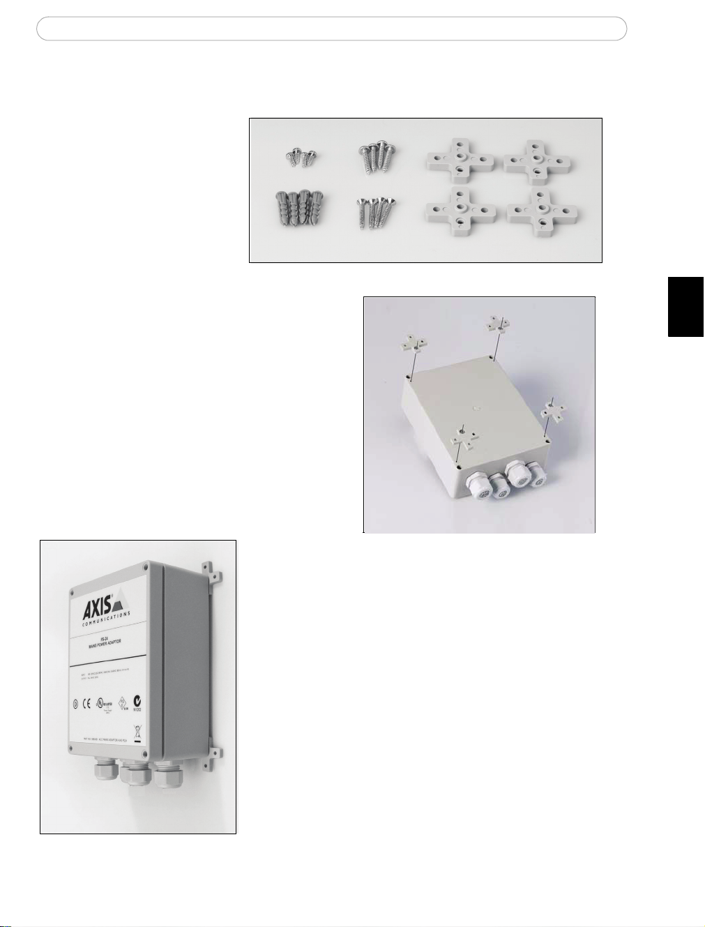
Mount the PS-24 box using the supplied holders
Package contents:
a) 4 holders
b) 4 wood screws
c) 4 screws for holders
d) 4 concrete plugs (5mm
drill)
e) 4 concrete screws
Using the supplied screws (c), attach the
plastic holders (a) to the PS-24 box.
ENGLISH
Using the appropriate screws for the wall material (wood
or concrete) and the weight of the unit, mount the PS-24
power supply box on a flat surface with the glands pointing downwards.
Page 4
PS-24 Mains Adaptor
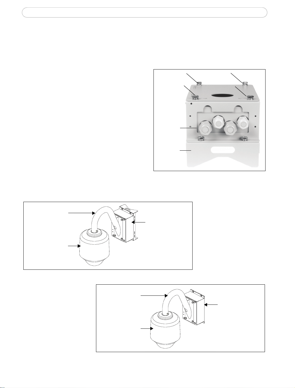
Cable
glands
Screws
Holder for
pole mount
Pole box mounting
Gooseneck
tube
Outdoor housing
for camera
Wall box mounting
Gooseneck
tube
Outdoor housing
for camera
Alternative installation - PSU box
The vandal-proof PSU box is an optional accessory which can be mounted either on a pole
or on a flat surface.
1. Remove the top lid of the PSU box by
removing the 4 screws.
2. Place the PS-24 with the 4 cable glands
in the opening at the bottom of the PSU
box.
3. Replace the lid and lock it by tightening
the 4 screws.
4. Use the holder for the pole mount or use
the supplied screws to mount the PSU on
a pole or a flat surface.
5. Follow the instructions for the outdoor
housing to complete the installation.
Note:
• Use 4pcs. sleeve anchor with flange nut, drill size 6mm, M6, length >= 50mm (concrete screw, not included).
• Pole mount - the recommended pole diameter for this pole box is 130-140mm.
Examples of installation (PSU box and pole/wall mount)
Page 5
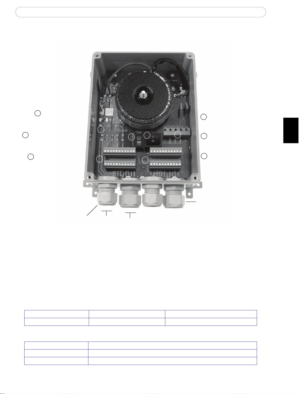
PS-24 Mains Adaptor
Voltage selector switch
(115V/230V)
Terminal connectors
Outer ring
Power switch
Terminal connectors
(From camera)
(To camera)
Cable gland
The outdoor power supply contains two sets of terminal connectors to provide easy wiring for alarm inputs/outputs
AC & DC Output
AC Input
1
2
3
4
5
6
(not used)
ON(1) OFF(0)
230VAC/115VAC
10-14mm
6-12mm
1
2
3
4
5
6
PS-24 Mains Power Adaptor
ENGLISH
Important!
• Warning - high voltage. Read through the instructions before starting the installation. The electrical connection
should be made by an authorized electrician. Please observe relevant national and local regulations for the
installation.
• AXIS PS-24 is designed to be part of an IT power system. Ground is not connected internally in the power
Cables
supply.
Power cable (not supplied) (6) AC Input connector Copper cables: AWG 16-18 or 1.5mm
Input cables (not supplied) (2) Terminal connectors AWG 16-28 or 1.5mm2 cables
AXIS PS-24 Specifications
AC Input: 100-120VAC / 220-240VAC, max 800mA / 400mA, 80VA
AC Output for 100-120VAC: 24VAC, max 40VA at -20°C to +30° C or max 35VA at +31°Cto 50°C ambient temperature
AC Output for 220-240VAC 24VAC, max 50VA at -20°C to +30° C or max 35VA at +31°Cto 50°C ambient temperature
2
Page 6

PS-24 Mains Adaptor
4
5
6
4
Connect power to the PS-24
1. Remove the lid of the power supply by removing the 4 screws.
2. Make sure the power switch is set to ‘0’ (off).
Important!
The power switch does not break on both poles at the AC input. The power switch shall only be used to turn
the camera on/off. When the power switch is set to off, high voltage is still present in the AXIS PS-24
mains adaptor. Regard the switch in the building installation as disconnect device.
3. Make sure the voltage selector switch is in the correct position. The setting must
correspond to the input mains voltage i.e.:
• set the switch to 115V if you intend to power the unit from a 100-120V mains
voltage line.
• set the switch to 230V if you intend to power the unit from a 220-240V mains
voltage line.
4. Remove the outer ring of the cable gland and the plug, thread the mains cable (not
supplied) through the outer ring and then through the cable gland.
5. Connect the live wires to AC Input (230VAC or 115VAC). Tighten the outer ring
to secure the cable.
6. Refer to the installation section for your network camera for information on how to
connect the power and alarm inputs/outputs.
7. Check that the cables are securely tightened and that the voltage selector switch is in
the correct position.
Important!
Make sure the power switch is set to ‘0’ (off) until all cables have been connected and
the installation is complete.
For unused cable glands, do not remove the plug and make sure that the outer ring is
tightened securely.
Page 7

PS-24 Versorgungsnetzteil Netzteil
(c)
(b)
(a)
(d)
(e)
Verwenden Sie zur Montage des PS-24-Gehäuses die mitgelieferten Halterungen
Lieferumfang:
a) 4 Halterungen
b) 4 Holzschrauben
c) 4 Schrauben für
Halterungen
d) 4 Betondübel (5-mm-
Bohrdurchmesser)
e) 4 Betonschrauben
Befestigen Sie mit den beiliegenden
Schrauben (c) die Kunststoffhalterungen (a)
an der Rückseite des PS-24-Gehäuses.
DEUTSCH
Montieren Sie das PS-24-Gehäuse mit den
Verschraubungen nach unten zeigend auf einer
flachen Oberfläche. Verwenden Sie hierfür Schrauben,
die für das Deckenmaterial (Holz oder Beton) und das
Gewicht des Gehäuses geeignet sind.
Page 8

PS-24 Versorgungsnetzteil Netzteil
KabelAnschluss-
Schrauben
Halter für
Mastmontage
muffen
Mastmontage
Schwanenhals
rohr
Außengehäuse
für Kamera
Wandmontage
Schwanenhals
rohr
Außengehäuse
für Kamera
Alternative Installation - PSU-Gehäuse
Das zerstörungssichere PSU-Gehäuse (optionales Zubehör) kann auf glatten Oberflächen
und an Masten montiert werden.
1. Lösen Sie zum Öffnen des PSU-Gehäuses
die 4 Befestigungsschrauben.
2. Legen Sie das PS-24-Netzteil so
in das PSU-Gehäuse ein, dass die
Anschlussmuffen in die entsprechende
Öffnung des PSU-Gehäuses passen.
3. Setzen Sie den Gehäusedeckel wieder
auf, und befestigen Sie die 4 Schrauben.
4. Benutzen Sie die Halterung für die
Mastmontage, oder montieren Sie das
PSU-Gehäuse mit Hilfe der mitgelieferten
Schrauben auf einer glatten Oberfläche.
5. Befolgen Sie gegebenenfalls die
Anweisungen zur Außenmontage.
Hinweis:
Montagebeispiele (PSU-Gehäuse in Mast-/Wandmontage)
• Verwenden Sie 4 Hülsenanker mit Flanschmutter, Bohrdurchmesser 6 mm, M6, Länge >= 50 mm
(Betonschrauben, nicht mitgeliefert).
• Mastmontage - Empfohlener Mastdurchmesser für dieses Gehäuse 130 - 140 mm.
Page 9

PS-24 Versorgungsnetzteil Netzteil
Spannungswähler
E/A-Anschlüsse
Außenring
Netzschalter
E/A-Anschlüsse
(von Kamera)
(zu Kamera)
Anschlussmuffe
Das Netzteil für den Außenbereich ist mit zwei E/A-Anschlussleisten ausgestattet,
Ausgang Gleich-
Eingang Wechselstrom
1
2
3
4
5
6
(nicht belegt)
EIN (1), AUS (0)
230 V ~/115 V ~
10 - 14 mm
6 - 12 mm
1
2
3
4
5
6
(115 V / 230 V)
die eine Vielzahl von Anschlussvarianten für Signaleingänge/Signalausgänge bieten.
und Wechselstrom
PS-24 Versorgungsnetzteil
DEUTSCH
Wichtig!
• Achtung! Hochspannung! Lesen Sie die Bedienungsanleitung, bevor Sie mit der Montage beginnen.
Elektroarbeiten müssen von einem ausgebildeten Elektriker vorgenommen werden. Beachten Sie bei der
Montage die geltenden nationalen und lokalen Bestimmungen.
• AXIS PS-24 ist als Komponente für IT-Systeme konzipiert. Die Erdverbindung ist im Netzteil nicht intern
angeschlossen.
Kabel
Netzkabel (nicht mitgeliefert) (6) Eingang (Wechselstrom) Kupferkabel AWG 16 - 18 oder 1,5 mm
Eingangskabel (nicht mitgeliefert) (2) E/A-Anschlüsse AWG 16 - 28 oder 1,5 mm2 Kabel
AXIS PS-24 - Technische Daten
Eingang Wechselstrom: 100 - 120 V ~ / 220 - 240 V ~, max. 800 mA / 400 mA, 80 VA
Ausgang (Wechselstrom)
für 100 - 120 V ~:
Ausgang (Wechselstrom)
für 220 - 240 V ~:
24 V ~, max. 40 VA bei -20 °C bis +30 °C oder max. 35 VA bei +31 °C bis 50 °C
Umgebungstemperatur
24 V ~, max. 50 VA bei -20 °C bis +30 °C oder max. 35 VA bei +31 °C bis 50 °C
Umgebungstemperatur
2
Page 10

PS-24 Versorgungsnetzteil Netzteil
4
5
6
4
PS-24 an das Stromnetz anschließen
1. Lösen Sie zum Öffnen der Gehäuseklappe die 4 Befestigungsschrauben.
2. Schalten Sie den Netzschalter auf 'O' (Aus).
Wichtig!
Der Netzschalter unterbricht nicht beide Pole des Wechselstromeingangs. Er dient lediglich zum
Ein-/Ausschalten der Kamera. Auch wenn der Netzschalter in Stellung ‘0’, liegt am AXIS PS-24-Netzteil
weiterhin Hochspannung an. Betätigen zum Ausschalten des Geräts den Hauptschalter im Gebäude.
3. Setzen Sie den Spannungswähler in die richtige Position. Die Einstellung muss
der Spannung der äußeren Stromversorgung entsprechen, d.h.:
• Setzen Sie den Schalter auf Position 115V, wenn Ihre Netzstromversorgung
100 - 120 V liefert.
• Setzen Sie den Schalter auf Position 230V, wenn Ihre Netzstromversorgung
220 - 240 V liefert.
4. Lösen Sie den Außenring der Anschlussmuffen, führen Sie das Versorgungskabel
(nicht mitgeliefert) zuerst durch den Außenring und dann durch die Anschlussmuffe.
5. Verbinden Sie die Leiter- und Erdungskabel mit dem Wechselstromeingang
(230 V ~ oder 115 V ~). Schrauben Sie den Außenring wieder fest auf, um das
Kabel zu fixieren.
6. Informationen zur Verschaltung der Versorgungs- und Signalkabel Ihrer
Netzwerkkamera finden Sie in der Montageanleitung zur Kamera.
7. Vergewissern Sie sich, dass alle Kabel fest sitzen und der Spannungswähler
auf der richtigen Position steht.
Wichtig!
Vergewissern Sie sich, dass der Netzschalter auf '0' (Aus) gesetzt ist, bis alle Kabel
angeschlossen sind und Sie die Installation abgeschlossen haben.
Entfernen Sie nicht die Stecker der Kabelverschraubungen, die Sie nicht verwenden,
und vergewissern Sie sich, dass der äußere Ring festgezogen ist.
Page 11

PS-24 電源アダプター
(c)
(b)
(a)
(d)
(e)
付属のホルダーを使用して、PS-24 ボックスを取り付けます
パッケージの内容 :
a) ホルダー (4)
b) 木ねじ (4)
c) ホルダー用ねじ (4)
d) コンクリートプラグ
(4) (5mm ドリル )
e) コンクリートねじ (4)
付属のねじ (c) でプラスチックホルダー
(a) を PS-24 ボックスに取り付けます。
壁の素材 ( 木またはコンクリート ) およびユニットの
重量に合ったねじで、PS-24 電源装置ボックスを平ら
な場所に取り付けます。このとき、ケーブルグランド
が下を向くようにしてください。
日本語
日本語
Page 12

PS-24 電源アダプター
ケーブル
グランド
ねじ
ポール取り
ホルダー
付け用の
グースネック
チューブ
屋外ハウジング
( カメラ用 )
ボックスのポ
ール取り付け
グースネック
チューブ
屋外ハウジング
( カメラ用 )
ボックスの
壁面取り付
他の設置方法 - PSU ボックス
耐衝撃 PSU ボックスは、ポールまたは平らな場所に取り付けられるオプションのア
クセサリーです。
1. 4 本のネジを取り外し、PSU ボックス
の上部のフタを取り外します。
2. PSU ボックスの底の開口部に 4 つの
ケーブルグランドが入るように、
PS-24 を配置します。
3. フタを取り付け直し、4 本のねじを締
めてロックします。
4. ポール設置用のホルダーを使用する
か、または付属のねじを使用し、
PSU をポールまたは平らな場所に取り
付けます。
5. 屋外ハウジング用の指示にしたがっ
て、設置を完了します。
注記 :
設置例 (PSU ボックスおよびポール / 壁面取り付け )
•4個のスリーブアンカー ( フランジナット付き、ドリルサイズ 6mm、M6、長さ
≧50mm) ( コンクリートねじ、付属していません ) を使用します。
• ポール取り付け - このポールボックスの推奨のポール径は、130 ~ 140mm です。
Page 13

PS-24 電源アダプター
電圧セレクタースイッチ
ターミナルコネクター
外側リング
電源スイッチ
ターミナルコネクター
( カメラから )
( カメラへ )
ケーブルグランド
屋外用電源装置には、アラーム入力 / 出力用に簡単に配線できるよう、ターミナルコネクターが 2
AC & DC 出力
AC 入力
1
2
3
4
5
6
( 使用されていません )
オン (1) オフ (0)
230VAC/115VAC
10 ~ 14mm
6 ~ 12mm
1
2
3
4
5
6
セット付いています。
(115V/230V)
PS-24 電源アダプター
日本語
重要!
• 警告 - 高電圧。 設置を開始する前に、指示をすべてお読みください。 電気の接続は、資格を持った
電気技師が行ってください。 設置に関する国よび地域の規制を順守してください。
• AXIS PS-24 は、IT 電源システムの一部として設計されています。 接地は、電源装置内部で接地はさ
れていません。
ケーブル
電源ケーブル ( 付属していません ) (6) AC 入力コネクター 銅ケーブル : AWG 16-18 または 1.5mm
入力ケーブル ( 付属していません ) (2) ターミナルコネクター AWG 16-28 または 1.5mm2ケーブル
AXIS PS-24 の仕様
AC 入力 :100~ 120VAC / 220 ~ 240VAC、最大 800mA / 400mA、80VA
100 ~ 120VAC の AC 出力 : 24VAC、-20°C から +30° C で最大 40VA、または +31°C から 50°C の環境温
220 ~ 240VAC の AC 出力 24VAC、-20°C から +30° C で最大 50VA、または +31°C から 50°C の環境温
度で最大 35VA
度で最大 35VA
日本語
2
Page 14

PS-24 電源アダプター
4
5
6
4
PS-24 に電源を接続します
1. 4 本のネジを取り外して電源装置のフタを取り外します。
2. 電源スイッチ が ‘0’ ( オフ ) になっていることを確認します。
重要!
電源スイッチは、AC 入力の両極で切断を行いません。 電源スイッチは、カメラをオン / オフ
にするためのみに使用できます。 電源スイッチをオフにしても、AXIS PS-24 電源アダプター内
部は引き続き高電圧な状態にあります。 建物に設置されているスイッチを、切断装置として
扱ってくだい。
3. 電圧セレクタースイッチ が正しい位置になっていることを確認します。 入力
電源電圧に合った設定になっていることが必要です。
• 電源電圧 100-120V でユニットに電力を供給する場合は、スイッチを 115V
に設定してください。
• 電源電圧 220-240V でユニットに電力を供給する場合は、スイッチを 230V
に設定してください。
4. ケーブルグランドの外側リングとプラグを取り外し、電源ケーブル ( 付属して
いません ) を外側リングとケーブルグランドに通します。
5. AC 入力 (230VAC とグランドまたは 11 5VAC とグランド ) に活線とグランド
線を接続します。 外側リングを締めて、ケーブルを固定します。
6. 電力およびアラーム入力 / 出力の接続方法については、ご使用のネットワーク
カメラの設置に関するセクションを参照してください。
7. ケーブルがしっかりと締めてあり、電圧セレクタースイッチが正しい位置に
なっていることを確認してください。
重要!
ケーブルを接続し、設置を完了するまで、電源スイッチ が ‘0’ ( オフ ) になって
いることを確認してください。
未使用のケーブルグランドではプラグを取り外さないでください。外側リングがしっ
かりと締めてあることを確認してください。
Page 15

PS-24 메인 어댑터
(c)
(b)
(a)
(d)
(e)
제공된 홀더를 이용한 PS-24 장착 방법
패키지 내용물 :
a) 홀더 4 개
b) 목재용 나사 4 개
c) 홀더용 나사 4 개
d) 콘크리트용플러그
4 개 (5mm 드릴 )
e) 콘크리트 나사 4 개
제공된 나사 (c)를 사용하여 플라스틱 홀더
(a) 를 PS-24 박스에 부착합니다 .
벽면 재료 ( 나무 또는 콘크리트 ) 와 장비의 무게를 고려
하여 적합한 나사를 사용하십시오 . 평평한 표면에
PS-24 전원 공급박스를 장착하되 , 글랜드가 아래 방향
을 향하도록 하십시오 .
한국어
한국어
Page 16

PS-24 메인 어댑터
케이블
글랜드
나사
기둥 장
착용홀더
기둥 장착용 박스
튜브
카메라
거위목 형 연성
실외용 하우징
벽면 장착용 박스
튜브
거위목 형 연성
실외용 하우징
PSU 박스를 이용한 장착 방법
충격 방지용 PSU 박스 ( 별매품 ) 기둥 또는 평평한 표면에 장착할 수 있습니다 .
1. 나사 4 개를 제거하여 PSU 박스 상단 덮
개를 제거하십시오 .
2. PSU 박스 하부 개구부에 케이블 그랜드 4
개를 사용하여 PS-24 를 배치하십시오 .
3. 덮개를 다시 덮고 나사 4 개를 조여서 고
정시킵니다 .
4. 기둥 장착용 홀더를 사용하거나 제공된
나사를 사용하여 PSU 를 기둥 또는 평평
한 표면에 장착하십시오 .
5. 설치를 완료하려면 실외용 하우징 설치
에 대한 지침을 준수하십시오 .
참고 :
• 플랜지 너트와 함께 슬리브 앵커 4 개를 사용하십시오 . 드릴 크기 6mm, M6, 길이 >=50mm ( 콘크
리트용 나사 불포함 )
• 기둥 장착 - 본 기둥용 박스를 장착할 기둥의 권장 지름은 130-140mm 입니다 .
설치 예 (PSU 박스 및 기둥/벽면 장착 )
Page 17

PS-24 메인 전원 어댑터
전압 선택 스위치
(115V/230V)
터미널 커넥터
외측 링
전원 스위치
터미널 커넥터
(from camera)
(to camera)
케이블 글랜드
경보 입력 / 출력을 위한 배선 작업을 간편하게 실시하려면 실외전원 공급은 터미널 커넥터 2 개 세트로
AC 및 DC 출력
AC 입력
1
2
3
4
5
6
( 사용 안 함 )
ON(1) OFF(0)
230VAC/115VAC
10-14mm
6-12mm
1
2
3
4
5
6
이루어져야 합니다 .
PS-24 메인 어댑터
한국어
중요 !
• 고압 주의 - 설치 작업을 실시하기 전 먼저 설치 가이드를 읽어보십시오 . 전기 결선 작업은 반드시 인
가된 전기 기술자가 실시해야 합니다 . 설치 시 반드시 국내외 규정을 준수하여 주십시오 .
• AXIS PS-24 는 IT 전원 시스템 가운데 일부분으로 구성될 수 있도록 설계되었습니다 . 접지는 전원 공
급 장치에서 내부적으로 연결되어 있지 않습니다 .
케이블
전원 케이블 ( 제공되지 않음 ) (6) AC 입력 커넥터 구리 케이블 : AWG 16-18 또는 1.5mm
입력 케이블 ( 제공되지 않음 ) (2) 터미널 커넥터 AWG 16-28 또는 1.5mm2 케이블
AXIS PS-24 사양
AC 입력 : 100-120VAC / 220-240VAC, 최대 800mA / 400mA, 80VA
100-120VAC 를 위한 AC 출력 : 24VAC, 최대 40VA 주위 온도 -20~+30 °C 또는 최대 35VA 주위 온도 +31~50°C
220-240VAC 를 위한 AC 출력 :24VAC, 최대 40VA 주위 온도 -20~+30°C 또는 최대 35VA 주위 온도 +31~50°C
한국어
2
Page 18

PS-24 메인 어댑터
4
5
6
4
PS-24 에 전원 연결하기
1. 나사 4 개를 제거하여 전원 공급장치의 덮개를 제거하십시오 .
2. 전원 스위치가 ‘0’ ( 끔 ) 으로 되어 있는지 확인하십시오 .
중요 !
전원 스위치는 AC 입력에 해당하는 양쪽 기둥은 차단하지 않습니다 . 전원 스위치는 카메라 전원
공급/차단 에만 사용됩니다 . 전원 스위치가 꺼져 있어도 AXIS PS-24 메인 어댑터는 고압 상태입
니다 . 건물 설치 단계에서 스위치는 전원 연결 해제 장치로 간주됩니다 .
3. 전압 선택 스위치가 올바른 위치에 놓여 있는지 확인하십시오 . 설정은 입력
메인 전압과 일치해야 합니다 . 예를 들어
• 100-120V 메인 전압 전선으로 장치에 전원을 공급하려면 스위치를 115V 로 설
정하십시오 .
•220-240V 메인 전압 전선으로 장치에 전원을 공급하려면 스위치를 230V 로
설정하십시오 .
4. 케이블 글랜드과 플러그의 외측 링을 제거하고 외측 링 내부로 메인 케이블 ( 제
공되지 않음 )
넣고 난 후 케이블 글랜드 안으로 넣으십시오 .
5. 전원이 공급되는 전선을 AC 입력 (230VAC 또는 115 VAC ) 에 연결하십시오 . 외
측 링을 단단하게 조여서 케이블을 고정합니다 .
6. 네트워크 카메라의 전원 및 알람 입/출력을 연결하는 방법에 관한 내용은 설치
섹션을 참조하십시오 .
7. 케이블이 단단하게 고정되었는지 확인하고 전압 선택 스위치가 올바른 위치에 놓
여 있는지 확인하십시오 .
중요 !
모든
케이블이 연결되고 설치가 완료될 때까지 전원 스위치를 ‘0’ ( 끔 ) 인 상태로
유지하십시오 .
사용하지 않은 케이블 글랜드의 경우 플러그를 제거하지 마시고 외측 링을 단단하게 조
여주십시오 .
Page 19

Page 20

AXIS COMMUNICATIONS
<Product Name> Quick User’s Guide
PS-24 Power Supply Installation Guide Rev. 2.3 Part No. 39879
 Loading...