

Axis PS-24 Installation Manual

ENGLISH
DEUTSCH
PS-24 Mains Adaptor
Installation Guide

PS-24 Mains Adaptor
ENGLISH
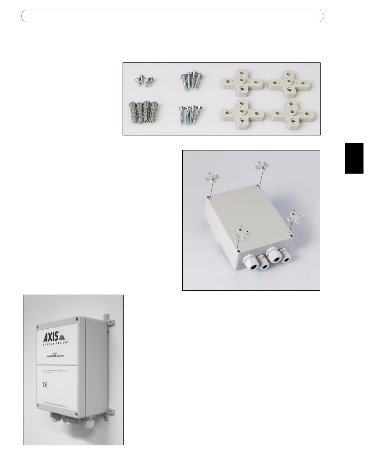
Mount the PS-24 box using the supplied holders
Package contents:
a) 4 holders
b) 4 wood screws
c) 4 screws for holders
d) 4 concrete plugs
(5mm drill)
e) 4 concrete screws
Using the supplied screws (c), attach the
plastic holders (a) to the PS-24 box.
Using the appropriate screws for the wall material
(wood or concrete) and the weight of the unit,
mount the PS-24 power supply box on a flat surface
with the glands pointing downwards.
(c)
(b)
(a)
(d)
(e)
PS-24 Mains Adaptor
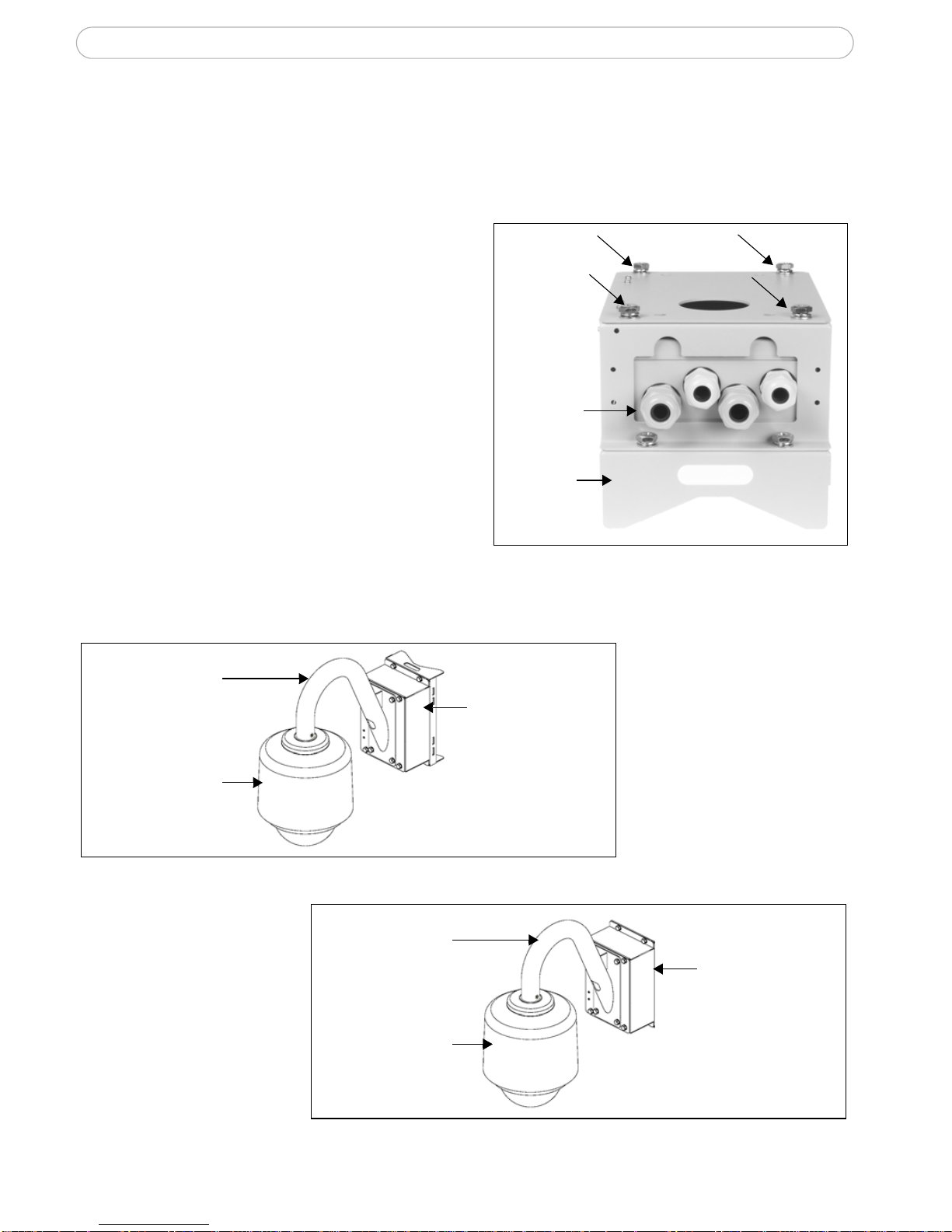
Alternative installation - PSU box
The vandal-proof PSU box is an optional accessory which can be mounted either on a pole
or on a flat surface.
1. Remove the top lid of the PSU box by
removing the 4 screws.
2. Place the PS-24 with the 4 cable glands
in the opening at the bottom of the PSU
box.
3. Replace the lid and lock it by tightening
the 4 screws.
4. Use the holder for the pole mount or use
the supplied screws to mount the PSU on
a pole or a flat surface.
5. Follow the instructions for the outdoor
housing to complete the installation.
Note:
• Use 4pcs. sleeve anchor with flange nut, drill size 6mm, M6, length >= 50mm (concrete screw, not included).
• Pole mount - the recommended pole diameter for this pole box is 130-140mm.
Examples of installation (PSU box and pole/wall mount)
Cable
glands
Screws
Holder for
pole mount
Pole box mounting
Gooseneck
tube
Outdoor housing
for camera
Wall box mounting
Gooseneck
tube
Outdoor housing
for camera
PS-24 Mains Adaptor
ENGLISH
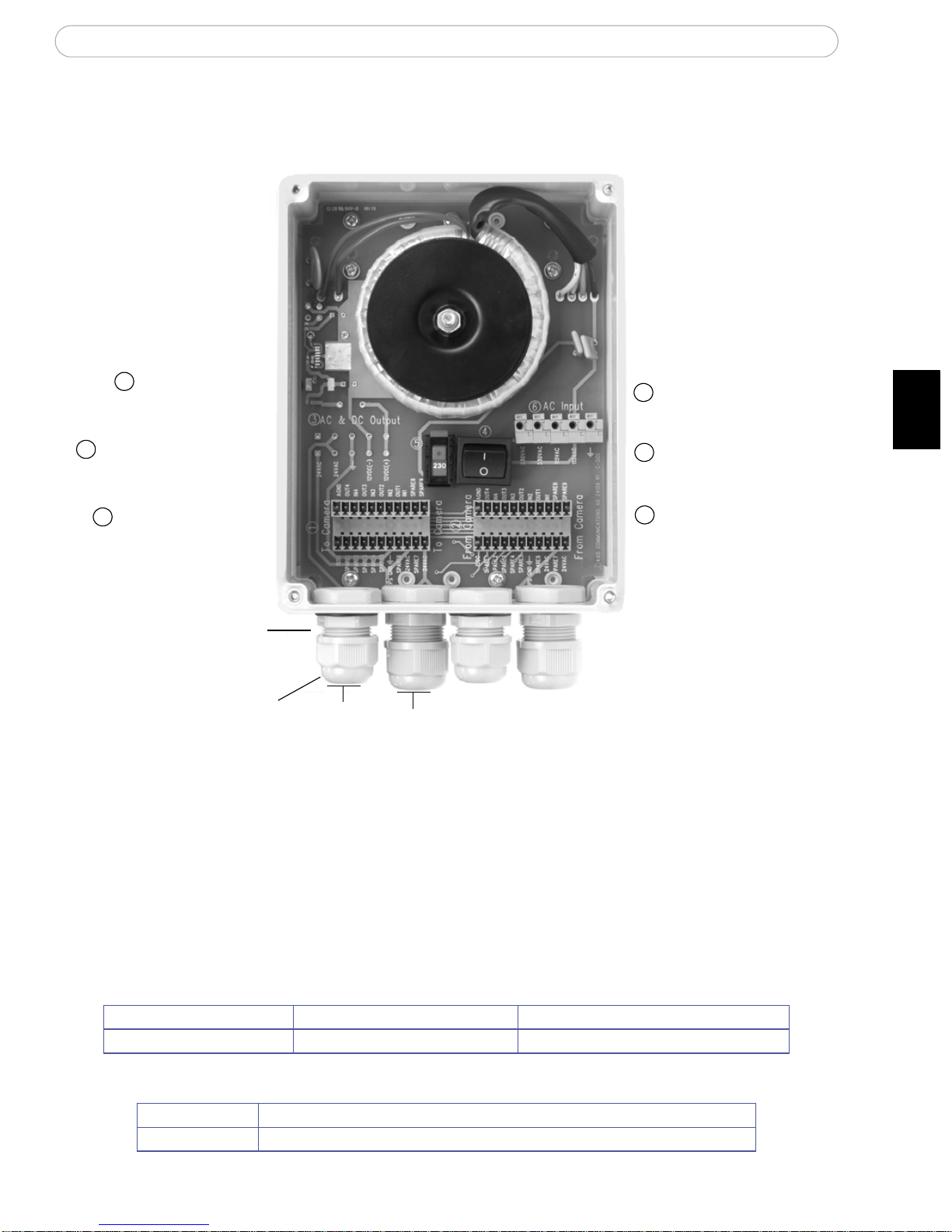
PS-24 Mains Power Adaptor
Important!
•Warning - high voltage. Read through the instructions before starting the installation. The electrical connection
should be made by an authorized electrician. Please observe relevant national and local regulations for the
installation.
•AXIS PS-24 is designed to be part of an IT power system. Ground is not connected internally in the power
supply.
Cables
AXIS PS-24 Specifications
Power cable (not supplied) (6) AC Input connector Copper cables: AWG 16-18 or 1.5mm
2
Input cables (not su pplied) (2) Terminal connectors AWG 16-28 or 1.5mm2 cables
AC Input: 100-120VAC / 220-240VAC, max 800mA / 400mA, 80VA
AC Output: 24VAC, max 63VA
Voltage selector switch
(115V/230V)
Terminal connectors
Outer ring
Power switch
Terminal connectors
(From camera)
(To camera)
Cable gland
The outdoor power supply contains two sets of terminal connectors to provide easy wiring for alarm inputs/outputs
AC & DC Output
AC Input
1
2
3
4
5
6
(not used)
ON(1) OFF(0)
230VAC/115VAC
10-14mm
6-12mm
 Loading...