

Axis PoE Midspan 8 port, PoE Midspan 16 port Installation Manual

INSTALLATION GUIDE
AXIS PoE MIDSPAN 8-Port
AXIS PoE Midspan 16-Port
ENGLISH DEUTSCH
FRAN
Ç
AIS
ITALIANO
ESPAÑOL
About this Document
This manual includes instructions for using and
managing the AXIS PoE MIDSPAN 8-Port/ AXIS PoE
Midspan 16-Port on your network. Later versions of this
document will be posted to the Axis Website.
Intellectual Property Rights
Axis AB has intellectual property rights relating to
technology embodied in the product described in this
document. In particular, and without limitation, these
intellectual property rights may include one or more of
the patents listed at http://www.axis.com/patent.htm
and one or more additional patents or pending patent
applications in the US and other countries.
Electromagnetic Compatibility (EMC)
This equipment generates, uses and can radiate radio
frequency energy and, if not installed and used in
accordance with the instructions, may cause harmful
interference to radio communications. However, there is
no guarantee that interference will not occur in a
particular installation.
If this equipment does cause harmful interference to
radio or television reception, which can be determined
by turning the equipment off and on, the user is
encouraged to try to correct the interference by one or
more of the following measures:
Re-orient or relocate the receiving antenna.
Increase the separation between the equipment and
receiver.
Connect the equipment to an outlet on a different
circuit to the receiver.
Consult your dealer or an experienced radio/TV
technician for help.
Shielded (STP) network cables must be used with this
unit to ensure compliance with EMC standards.
USA - This equipment has been tested and found to
comply with the limits for a Class B computing device
pursuant to Subpart B of Part 15 of FCC rules, which are
designed to provide reasonable protection against such
interference when operated in a commercial
environment. Operation of this equipment in a
residential area is likely to cause interference, in which
case the user at his/her own expense will be required to
take measures required to correct the interference.
Canada - This Class B digital apparatus complies with
Canadian ICES-003.
Europe - This digital equipment fulfills the
requirements for radiated emission according to limit B
of EN55022/1998, and the requirements for immunity
according to EN55024/1998 residential, commercial,
and light industry.
Japan - This is a class B product based on the standard
of the Voluntary Control Council for Interference from
Information Technology Equipment (VCCI). If this is used
near a radio or television receiver in a domestic
environment, it may cause radio interference. Install and
use the equipment according to the instruction manual.
Australia - This electronic device meets the
requirements of the Radio communications
(Electromagnetic Compatibility) Standard AS/NZS
CISPR22:2002.
Equipment Modifications
This equipment must be installed and used in strict
accordance with the instructions given in the user
documentation. This equipment contains no
user-serviceable components. Unauthorized equipment
changes or modifications will invalidate all applicable
regulatory certifications and approvals.
Every care has been taken in the preparation of this
manual. Please inform your local Axis office of any
inaccuracy or omission. Axis Communications AB cannot
be held responsible for any technical or typographical
errors and reserves the right to make changes to the
product and manuals without prior notice. Axis
Communications AB makes no warranty of any kind
with regard to the material contained within this
document, including, but not limited to, the implied
warranties of merchantability and fitness for a
particular purpose. Axis Communications AB shall not be
liable nor responsible for incidental or consequential
damages in connection with the furnishing,
performance or use of this material.
Support
Should you require any technical assistance, please
contact your Axis reseller. If your questions cannot be
answered immediately, the reseller will forward your
queries through the appropriate channels to ensure a
rapid response. If you are connected to the Internet, you
can:
• Download user documentation and firmware updates
• Find answers to resolved problems in the FAQ database
• Search by product, category, or phrases
• Report problems to Axis support by logging in to your
private support area
• Visit Axis Support at www.axis.com/techsup/
RoHS
This product complies with both the European
RoHS directive, 2002/95/EC, and the Chinese
RoHS regulations, ACPEIP.
WEEE Directive
The European Union has enacted a Directive
2002/96/EC on Waste Electrical and Electronic
Equipment (WEEE Directive). This directive is
applicable in the European Union member
states.
The WEEE marking on this product or its documentation
indicates that the product must not be disposed of
together with household waste. To prevent possible
harm to human health and/or the environment, the
product must be disposed of in an approved and
environmentally safe recycling process. For further
information on how to dispose of this product correctly,
contact the product supplier, or the local authority
responsible for waste disposal in your area.
Business users should contact the product supplier for
information on how to dispose of this product correctly.
This product should not be mixed with other commercial
waste.
AXIS PoE MIDSPAN 8-Port/AXIS PoE Midspan 16-Port is
identical to the Phihong
PoE370U-480-8/PoE370U-480-16.

AXIS PoE Midspans 8P/16P Page 3
Before you begin
Package Contents
• PoE Midspan
• Mains cable
• Two 19-inch rack mounting brackets
• Four M4 x 8mm Philips flat head screws
• AXIS warranty statement
• Four rubber feet
• Manual
Precautions
Please read the following carefully before installing and connecting the system to a power source.
ENGLISH
• Only qualified and trained service personnel (in accordance with IEC 60950 and AS/NZS 3260)
should install, replace, or service the equipment. Install the system in accordance with Country,
National, or the U.S. National Electric Code if you are in the United States.
• The building where this product is used requires a fuse or circuit breaker no larger than 15 A for
120 VAC (U.S.A.) or 10 A, 230 VAC (international). The building facility must protect the AXIS
PoE Midspans 8P/16P from over current or short-circuits.
• Read the Midspan Hardware Setup procedure before connecting the AXIS PoE Midspans 8P/16P
to a power source (including power cord requirements).
• Do not operate the product in an area that exceeds the maximum recommended ambient temperature of 104 ºF/ 40 ºC to avoid overheating the AXIS PoE Midspans 8P/16P. Allow at least 3
to 4 inches/ 7.6 to 10.2 cm clearance around all ventilation openings.
• Do not stack the chassis on any other equipment to support its weight. Shelf mounted equipment requires a stable and durable surface. Do not push or pull on the Midspan while installing.
• The AXIS PoE Midspans 8P/16P consist of two rows of "Data” and "Data & Power" ports. The
ports use RJ-45 data sockets. Connect only RJ-45 data cables to these sockets. Do not connect
telephone cables into these ports.
• Do not work on the AXIS PoE Midspans 8P/16P system or connect or disconnect cables, when
there is lightning.
• The AC or DC plug/socket combination must be accessible at all times, as it is the main disconnect device to the product.
• Before servicing the product, always disconnect the product from its AC source.
• Abide by appropriate national laws and regulations when it comes to discarding this product.
Page 4 AXIS PoE Midspans 8P/16P
Power Cord Requirements
Power cords must meet the requirements for the country they are used in.
USA and Canada • The cord must have a minimum of 10A rated current competence.
• The cord must be CSA or UL approved.
• The minimum requirement for the flexible cord is:
• 18 AWG (10A)
• Three-conductor (line, neutral, ground)
• Type SV (Stranded Vacuum Rubber Jacketed) or SJ (Stranded Junior Rubber
Jacketed) or SVT (Stranded Vacuum Rubber Jacketed Themoplastic) or SJT
(Stranded Junior Themoplastic)
• The plug must be earth-grounded with a NEMA 5-15P (15A, 125 V) or
NEMA 6-15P (15A, 250 V) configuration.
Europe and South America Switzerland: The supply plug must comply with SEV/ASE 1011.
Denmark: The supply plug must comply with section 107-2-D1, standard DK2-1a
or DK2-5a.
United Kingdom: The Midspan is covered by General Approval (section 16.16.060),
NS/G/12345/J100003, for indirect connection to a public telecommunication
system
France and Peru: IT equipment cannot power this device. In the case of an IT
powered device, the unit needs to be powered by 230 V through an isolation
transformer with a ratio of 1:1 and the secondary connection (Neutral) is properly
grounded.
• The Midspan must have access to a power outlet. Disconnect the power cord from the outlet, to
eliminate power from the device.
• The flexible cord that connects to the Midspan must have a configuration to connect with an
EN60320/IEC320 inlet connector.
• According to the EN60950/IEC 950 specifications, this device functions under SELV (Safety
Extra Low Voltage) conditions. The conditions are true if the equipment and the connected
device functions under SELV conditions.
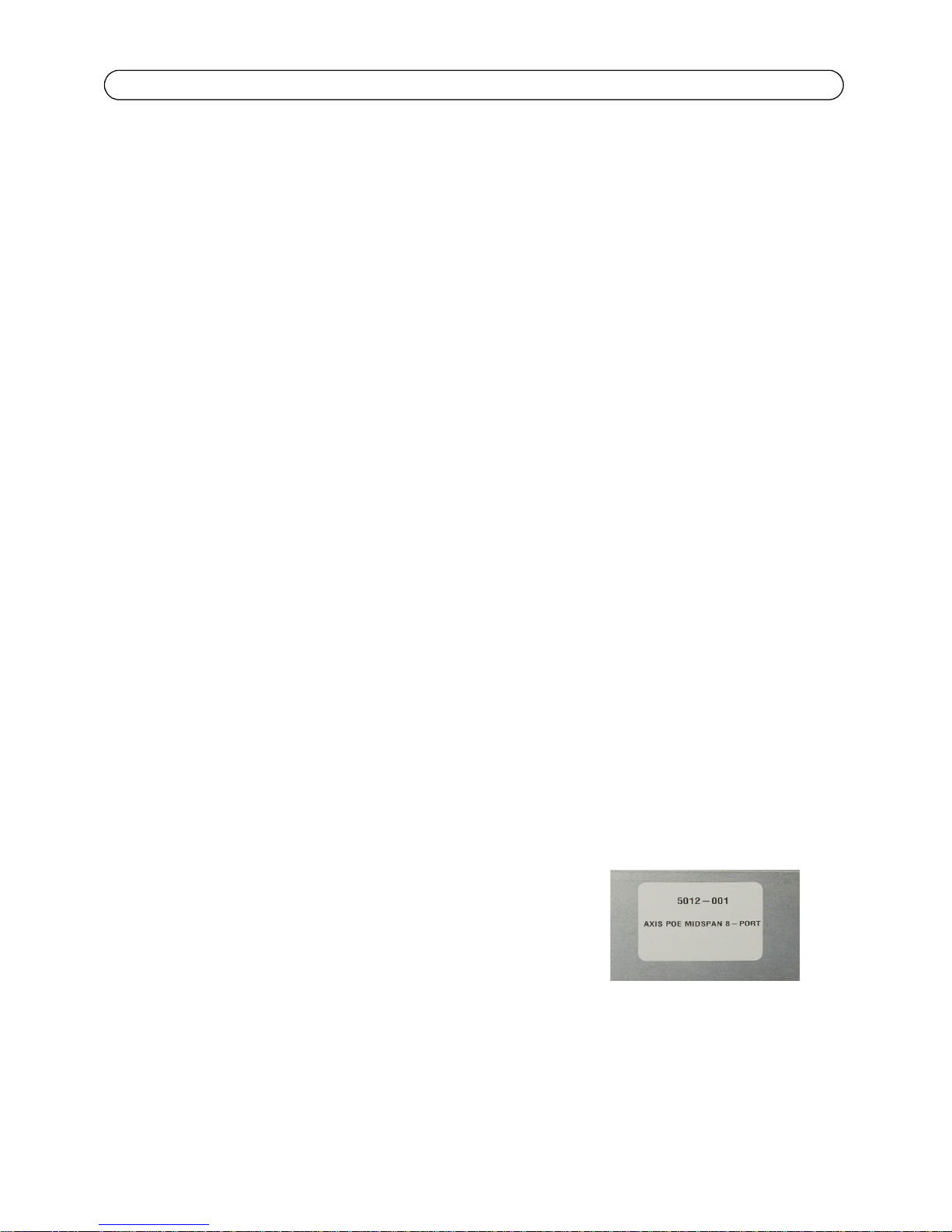
• The AXIS PoE Midspans 8P/16P meet the UL/cUL per
EN60950 safety standard. This is displayed in the back side
of the product.
AXIS PoE Midspans 8P/16P Page 5
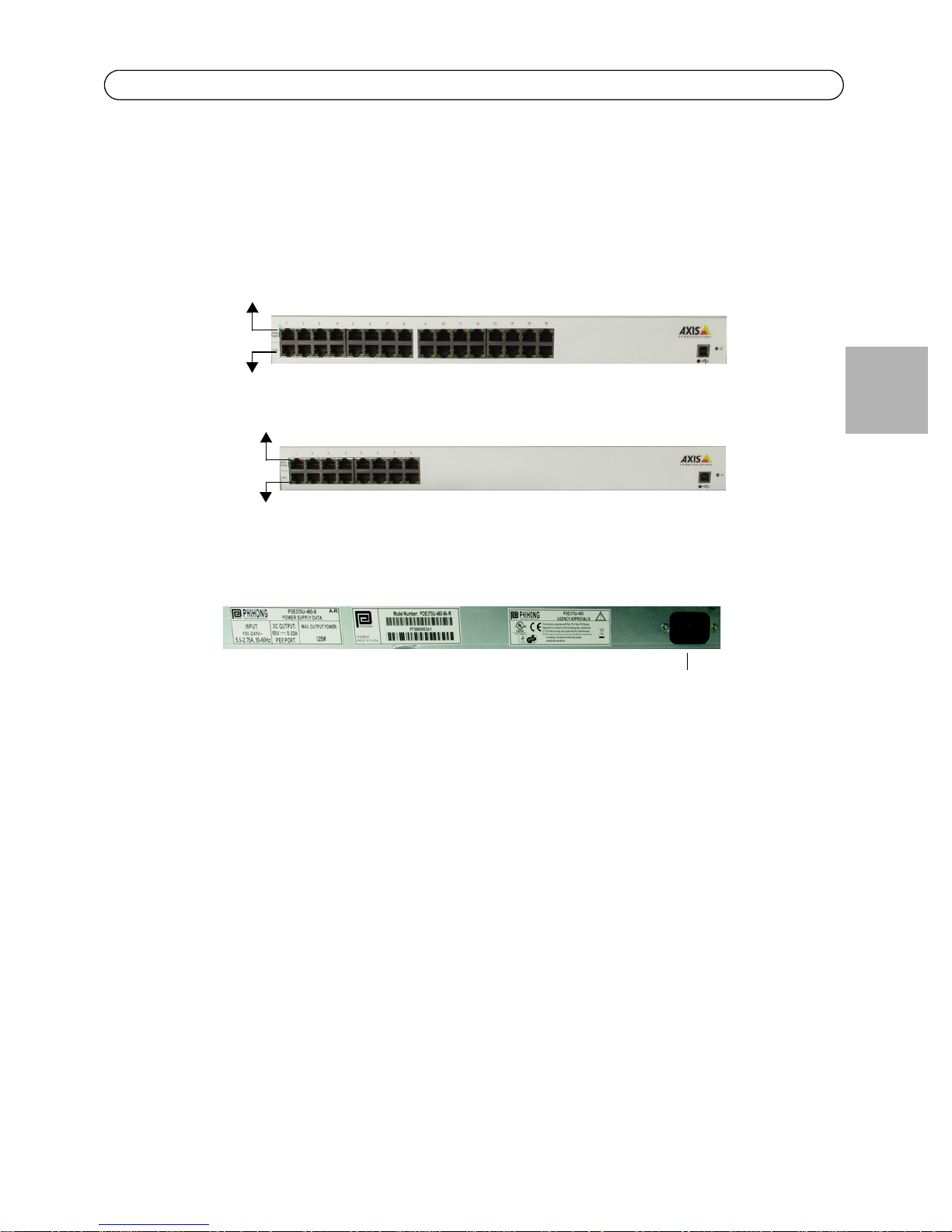
Data
Data and Power
Data
Data and Power
Power connector
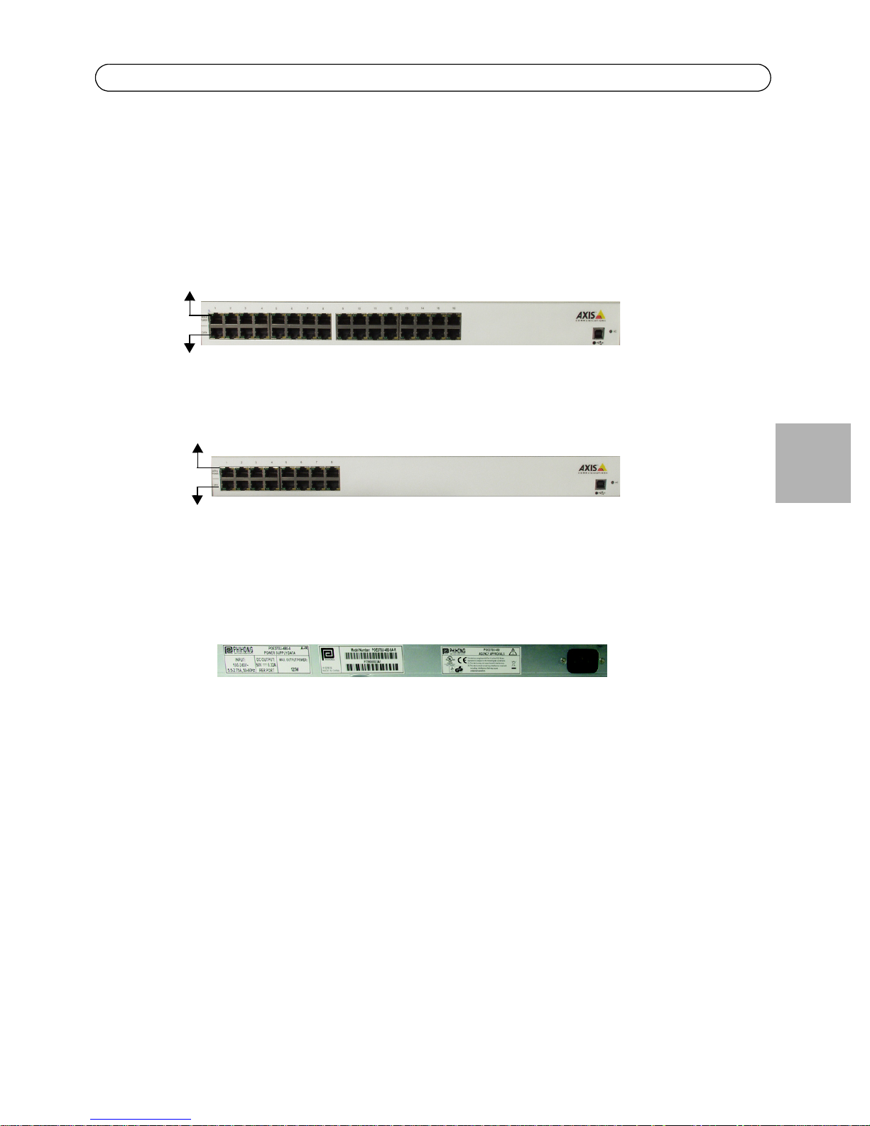
Hardware Setup
Product overview
Front side of AXIS PoE 16 port & 8 port Midspan
ENGLISH
AC Power connector at the back
Data Input Ports
The AXIS PoE Midspans 8P/16P have 10Base-T/100Base-TX data input ports, that have straightwired configuration. These ports carry Ethernet data (Tx/Rx) over the standard 2-wire pairs (pins 1/
2 and 3/6).
Data and Power Output Ports
The AXIS PoE Midspans 8P/16P Data and Power ports have straight-wire configuration. They are
designed to carry Ethernet data and DC power over the standard 2-wire pairs (pins 1/2 and 3/6; PoE
mode A).

Page 6 AXIS PoE Midspans 8P/16P
Installation
Connecting Power Cables
The AC power cable is connected to the AC power connector located in the rear side of the AXIS PoE
Midspans 8P/16P and the power outlet.
Connecting Ethernet Cables
The ports in the product’s front panel are configured as ‘route through’ ports for all the eight/
sixteen RJ-45 connectors. Use Category 5 cabling in making connections.
1. Connect cables from the ethernet switch to the data ports - on the bottom row of the
AXIS PoE Midspans 8P/16P.
2. Connect the cables from the IEEE 802.3af powered devices to the corresponding Data
and Power ports on the top row of the AXIS PoE Midspans 8P/16P.
Powering Up
AXIS PoE Midspans 8P/16P are powered by the power cord. In order to apply or remove power to or
from the Midspan, connect or disconnect the AC power cable to or from the AC power connector on
the rear side of the unit.
With AC power the unit starts-up and the internal fans are active. The device runs through a quick
power-on test, which takes less than 10 seconds. During this period, all ports are initially disabled
and the port indicators light up. The sequence of the port LEDs are shown in the section below LED Indicator. Ports now operate under normal conditions.
AXIS PoE Midspans 8P/16P Page 7
LED Indicators
Conditions
Indicators
Power LED Midspan not
Data & Power Port disabled Port
Off Green Orange
static blinking static blinking
Midspan
powered
powered
connected
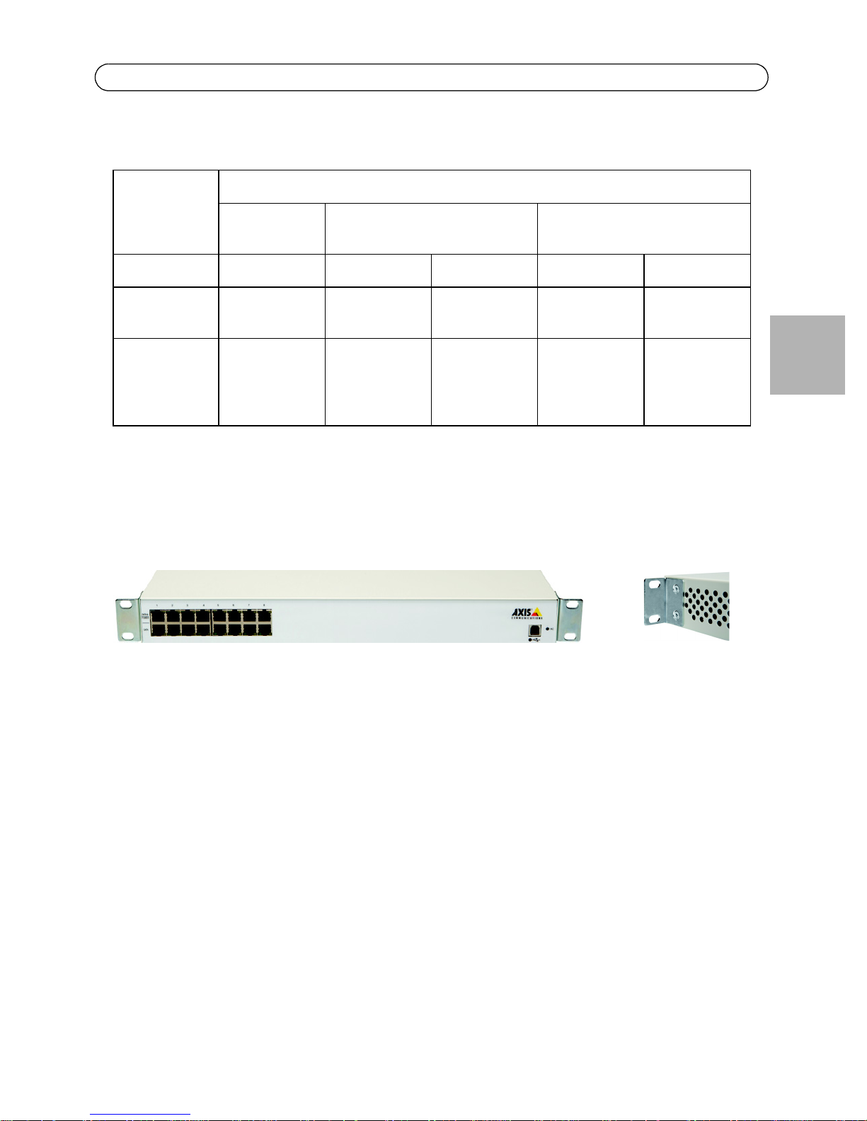
Rack-Mounting Installation
n/a n/a n/a
Port
connected;
data port
disconnected
Port has an
error
Port is
disconnected,
but enabled
ENGLISH
Position the Midspan on the rack. Arrange the mounting bracket to the corresponding screw holes
in the Midspan. Keep the screw area visible to insert screws, and then tighten them.
Page 8 AXIS PoE Midspans 8P/16P
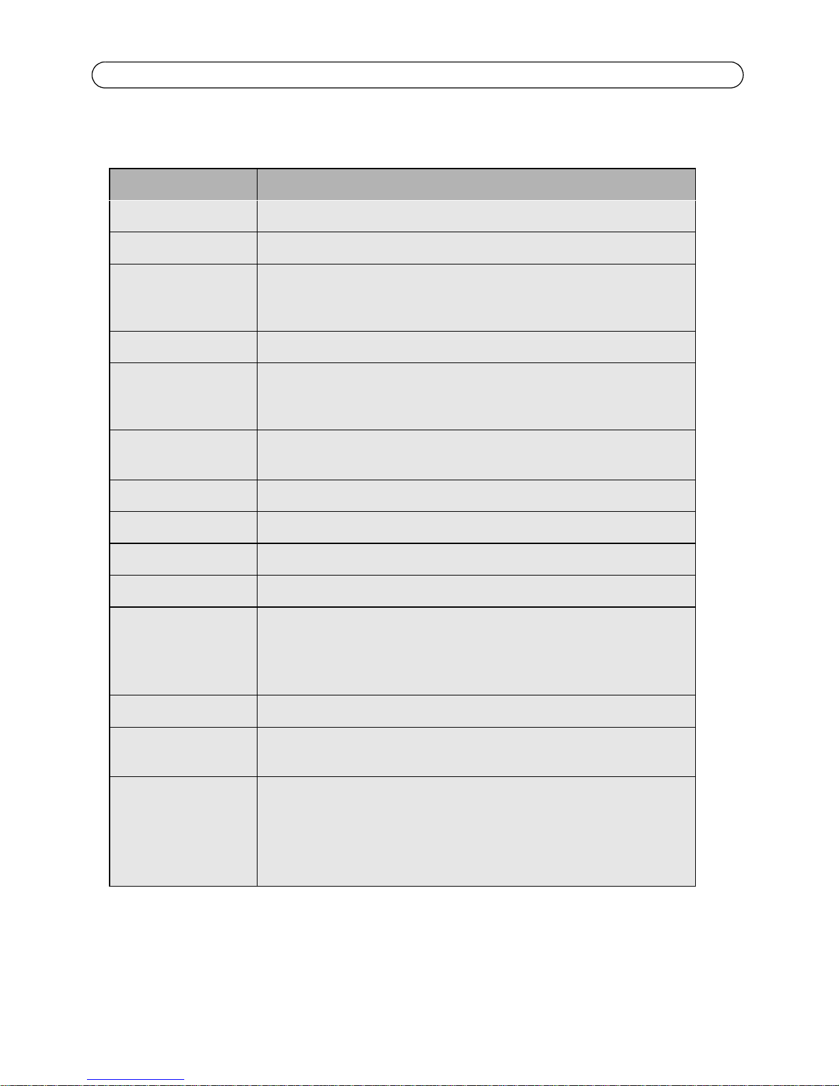
Technical Specifications
Parameters Specifications
Data rate 10/100/1000 Mbps
Mounting Prepared for 19”, 1U rack installation
Installation and
management
Port auto-sensing Standard IEEE 802.3af auto-sensing.
Display and indicators All port interfaces are located on the front panel for easy access and real-
Dimensions (HxWxD)
and weight
Operating conditions 0 - 40 °C (32 - 104 °F): Humidity max 90% RH (non-condensing)
Connectors Shielded RJ–45, EIA 568A and 568B
Network cables Shielded category 5 (or higher) Ethernet; max. length up to 100 m (328 ft)
Wiring Mode A; data and power provided over pairs 1/2 (+) and 3/6 (-)
Input power • AC input voltage range: 90 - 264 V AC
Plug-and-play installation. Midspans automatically detect all Power Over
Ethernet enabled devices and supply inline power. Local LED management
display.
time network monitoring. System: AC power, Channel indicator - power and
fault
44.5 x 228 x 438 mm (1.75” x 8.98” x 17.26”) 4.08 kg (9 lbs)
• AC Input frequency: 47 - 63 Hz
• AC input current: 4.5 A (RMS) max. for 90 V AC, 2.25 A (RMS)
max. for 240 V AC
Output power 48 V DC (max 15.4 W/port)
Compliance IEEE 802.3 standard (when no inline power is supplied) and
IEEE 802.3af, DTE Power via Media Dependent Interface (MDI)
Approvals • TUV EN 60950
• FCC Class B, EN55022 Class B, EN61000-4-2. EN61000-4-3,
• EN61000-4-4, EN61000-4-5, EN61000-4-6, EN61000-4-11,
• EN61000-3-2 Class A
• Safety: cUL/UL, TUV, CE
AXIS PoE Midspans 8P/16P Page 9
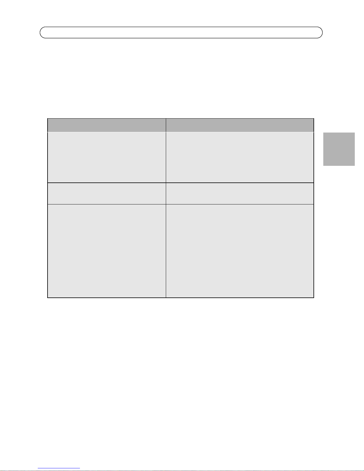
Troubleshooting
If problems occur with the Midspan, please refer to the table below. The troubleshooting solutions
provided can only solve minor problems. If your problem is not listed, please contact our local office
for further technical assistance.
Problem Possible Solutions
Midspan does not power up 1. Ensure that AC power cord is connected.
2. Ensure that AC power cord is in good condition.
3. If neither of the above is the problem, disconnect the
AC power cord and reconnect. Observe Port LEDs to verify
proper power up.
AC LED unlit Verify if the Midspan is properly connected to an AC
power source.
ENGLISH
Data and Power Port LED do not light 'green' Ensure Ports are connected to a Network.
Verify the following:
1. Power is applied to the Midspan
2. Network Ethernet cable is connected to the Data port
3. Powered device Ethernet cable is connected to the Data
& Power port
4. The right kind of Ethernet cable is used; do not use
crossover-type Ethernet cable
5. Cable pairs are connected to corresponding ports.


Contenu de l'emballage
• Midspan PoE
•Câble secteur
• Deux supports de montage en baie de 19 pouces
• Quatre vis à tête plate Philips M4 x 8 mm
• Déclaration de garantie AXIS
• 4 pieds en caoutchouc
• Manuel
Informations de sécurité
Page 11
Veuillez lire attentivement les informations qui suivent avant d'installer et de connecter le système
à une source d'alimentation.
Remarque:
Seul le personnel de maintenance qualifié et formé (conformément aux normes IEC
60950 et AS/NZS 3260) est autorisé à installer, remplacer ou dépanner le matériel.
Installez le système conformément aux procédures en vigueur dans votre pays, ou au
U.S. National Electric Code si vous êtes aux États-Unis.
• Le bâtiment dans lequel ce produit doit être utilisé doit être muni d'un fusible ou d'un disjoncteur n'excédant pas 15 A pour 120 Vca (États-Unis) ou 10 A pour 230 Vca (international).
L'installation du bâtiment doit protéger le midspan AXIS PoE 8P/16P des surtensions et des
courts-circuits.
• Consultez la procédure d'installation du matériel avant de connecter le midspan AXIS PoE 8P/
16P à une source d'alimentation (notamment les conditions relatives au câble d'alimentation).
• N'utilisez pas le produit dans un local dépassant la température ambiante maximale recommandée de 40 °C/104 °F, afin d'éviter la surchauffe du midspan AXIS PoE 8P/16P. Prévoyez un
dégagement d'au moins 7,6 à 10,2 cm (3 à 4 pouces) au niveau de tous les évents.
• N'empilez pas le châssis sur d'autres appareils afin d'en soutenir le poids. L'équipement monté
sur étagère nécessite une surface stable et résistante. Ne poussez pas ou ne tirez pas sur le midspan pendant que vous l'installez.
• Le midspan AXIS PoE 8P/16P comporte deux rangées de ports « Données » et « Données & Alimentation ». Ces ports utilisent des connecteurs de données RJ-45. Ne connectez pas de câbles
téléphoniques à ces ports. Connectez-y uniquement des câbles de données RJ-45.
• Ne travaillez pas sur le système midspan AXIS PoE 8P/16P et ne connectez ou ne déconnectez
aucun câble en cas d'orage.
• La combinaison fiche/prise CA ou CC doit être accessible à tout moment, car elle constitue le
principal dispositif de déconnexion du produit.
• Avant toute intervention sur le produit, débranchez-le toujours de sa source de CA.
• Adhérez à la réglementation nationale appropriée pour la mise au rebut du produit.
FRAN
Ç
AIS
Page 12
Conditions requises pour les câbles d'alimentation
Les câbles d'alimentation doivent être conformes aux conditions requises par le pays dans lequel ils
sont utilisés.
États-Unis et
Canada
Europe et Amérique
du Sud
• Le câble doit supporter au minimum une intensité nominale de 10 A.
• Le câble doit être agréé CSA ou UL.
• Les conditions minimales suivantes sont requises pour le câble flexible :
• 18 AWG (10 A)
• Trois conducteurs (phase, neutre, terre)
• Type SV (Stranded Vacuum Rubber Jacketed), SJ (Stranded Junior Rubber Jacketed), SVT (Stranded Vacuum Rubber Jacketed Themoplastic) ou SJT (Stranded
Junior Themoplastic)
• "La prise doit être mise à la terre avec une configuration NEMA 5-15P (15 A,
125 V) ou NEMA 6-15P (15 A, 250 V).
Suisse : la prise d'alimentation doit être conforme à la norme SEV/ASE 1011.
Danemark : la prise d'alimentation doit être conforme à la section 107-2-D1 de la
norme DK2-1a ou DK2-5a.
Royaume-Uni : La réglementation relative au midspan est traitée dans le General
Approval (section 16.16.060) NS/G/12345/J100003 sur les connexions indirectes à un
système de télécommunications publiques.
France et Pérou : Aucun matériel informatique ne peut alimenter cet appareil. Dans le
cas d'un appareil alimenté par un système informatique, l'unité doit être alimentée à
230 V par l'intermédiaire d'un transformateur de séparation présentant un rapport de
1:1 et la connexion secondaire (Neutre) doit bénéficier d'une mise à la terre correcte.
• Le midspan doit avoir accès à une prise de courant. Débranchez le câble d'alimentation de la
prise pour couper l'alimentation de l'appareil.
• Le câble flexible qui se connecte au midspan doit présenter une configuration appropriée à un
branchement sur un connecteur d'entrée EN60320/IEC320.
• Selon les spécifications de la norme EN60950/IEC 950, cet appareil fonctionne dans des conditions SELV (Safety Extra Low Voltage). Ces conditions sont remplies si l'équipement et l'appareil
connecté fonctionnent dans des conditions SELV.
• Le midspan AXIS PoE 8P/16P est conforme UL/cUL selon la
norme de sécurité EN60950. Ces informations apparaissent à
l'arrière du produit.
Installation du matériel Page 13
Face avant du midspan
AXIS PoE 16P
Données
Données et alimentation
Données
Données et alimentation
Connecteur d'alimentation CA à l'arrière
Installation du matériel
Aspect
FRAN
Ç
AIS
Ports d'entrée de données
Le midspan AXIS PoE 8P/16P comporte des ports d'entrée de données 10Base-T/100Base-TX à
raccordement direct. Ces ports acheminent des données Ethernet (transmission/réception) sur les
paires 2 fils standard (broches 1/2 et 3/6).
Ports de sortie données et alimentation
Les ports de données et d'alimentation du midspan AXIS PoE 8P/16P présentent une configuration à
raccordement direct. Ils sont conçus pour acheminer des données Ethernet et du courant continu
sur les paires 2 fils standard (broches 1/2 et 3/6 ; PoE mode A).

Page 14 Installation
Installation
Connexion des câbles d'alimentation
Le câble d'alimentation CA se branche sur le connecteur d'alimentation CA situé sur la face arrière
du midspan AXIS PoE 8P/16P et sur la prise de courant.
Connexion des câbles Ethernet
Les ports présents sur le panneau avant du produit sont configurés en tant que ports
d'acheminement pour l'ensemble des huit/seize connecteurs RJ-45. Utilisez des câbles de catégorie
5 pour établir les connexions.
1. Connectez les câbles entre le commutateur Ethernet et les ports de données, dans la
rangée inférieure du midspan AXIS PoE 8P/16P.
2. Connectez les câbles entre les appareils IEEE 802.3af et les ports de données et
d'alimentation correspondants, dans la rangée supérieure du midspan AXIS PoE 8P/16P.
Mise sous tension
Le midspan AXIS PoE 8P/16P est alimenté par le câble secteur. Pour mettre le midspan sous tension
ou hors tension, branchez le câble d'alimentation CA sur le connecteur CA situé à l'arrière de l'unité
ou débranchez-le.
Dès qu'elle est alimentée en CA, l'unité démarre et les ventilateurs internes s'activent. L'appareil
procède à un bref test à la mise sous tension, qui dure moins de dix secondes. Pendant cette
période, les ports sont désactivés et leurs témoins lumineux s'allument. La séquence des témoins
DEL des ports est fournie dans la section ci-dessous - Témoin DEL. Les ports fonctionnent ensuite
dans des conditions normales.
 Loading...