

Axis P1354-E, P1357-E Installation Manual
AXISP13-ESeries
ENGLISH
FRANÇAIS
DEUTSCH
ITALIANO
ESPANÕL
ò
ò
¨
¨
¾
¾
AXISP1354-ENetworkCamera
AXISP1357-ENetworkCamera
InstallationGuide

LegalConsiderations
Videoandaudiosurveillancecanberegulatedbylawsthat
varyfromcountrytocountry.Checkthelawsinyourlocal
regionbeforeusingthisproductforsurveillancepurposes.
Thisproductincludesone(1)H.264decoderlicenseand
one(1)AACdecoderlicense.Topurchasefurtherlicenses,
contactyourreseller.
Liability
Everycarehasbeentakeninthepreparationofthis
document.PleaseinformyourlocalAxisofceofany
inaccuraciesoromissions.AxisCommunicationsABcannot
beheldresponsibleforanytechnicalortypographicalerrors
andreservestherighttomakechangestotheproductand
manualswithoutpriornotice.AxisCommunicationsAB
makesnowarrantyofanykindwithregardtothematerial
containedwithinthisdocument,including,butnotlimited
to,theimpliedwarrantiesofmerchantabilityandtnessfor
aparticularpurpose.AxisCommunicationsABshallnot
beliablenorresponsibleforincidentalorconsequential
damagesinconnectionwiththefurnishing,performance
oruseofthismaterial.Thisproductisonlytobeusedfor
itsintendedpurpose.
IntellectualPropertyRights
AxisABhasintellectualpropertyrightsrelatingto
technologyembodiedintheproductdescribedinthis
document.Inparticular,andwithoutlimitation,these
intellectualpropertyrightsmayincludeoneormoreof
thepatentslistedatwww.axis.com/patent.htmandoneor
moreadditionalpatentsorpendingpatentapplicationsin
theUSandothercountries.
Thisproductcontainslicensedthird-partysoftware.See
themenuitem“About”intheproduct’suserinterfacefor
moreinformation.
ThisproductcontainssourcecodecopyrightAppleComputer,
Inc.,underthetermsofApplePublicSourceLicense2.0
(seewww.opensource.apple.com/apsl).Thesourcecodeis
availablefromhttps://developer.apple.com/bonjour/
EquipmentModications
Thisequipmentmustbeinstalledandusedin
strictaccordancewiththeinstructionsgiveninthe
userdocumentation.Thisequipmentcontainsno
user-serviceablecomponents.Unauthorizedequipment
changesormodicationswillinvalidateallapplicable
regulatorycerticationsandapprovals.
TrademarkAcknowledgments
AXISCOMMUNICATIONS,AXIS,ETRAX,ARTPECandVAPIX
areregisteredtrademarksortrademarkapplicationsofAxis
ABinvariousjurisdictions.Allothercompanynamesand
productsaretrademarksorregisteredtrademarksoftheir
respectivecompanies.
Apple,Boa,Apache,Bonjour,Ethernet,InternetExplorer,
Linux,Microsoft,Mozilla,Real,SMPTE,QuickTime,UNIX,
Windows,WindowsVistaandWWWareregistered
trademarksoftherespectiveholders.Javaandall
Java-basedtrademarksandlogosaretrademarksor
registeredtrademarksofOracleand/oritsafliates.
TM
UPnP
isacerticationmarkoftheUPnP
Corporation.
SD,SDHCandSDXCaretrademarksorregisteredtrademarks
ofSD-3C,LLCintheUnitedStates,othercountriesorboth.
Also,miniSD,microSD,miniSDHC,microSDHC,microSDXC
arealltrademarksorregisteredtrademarksofSD-3C,LLC
intheUnitedStates,othercountriesorboth.
TM
Implementers
RegulatoryInformation
Europe
ThisproductcomplieswiththeapplicableCEmarking
directivesandharmonizedstandards:
•ElectromagneticCompatibility(EMC)Directive
2004/108/EC.SeeElectromagneticCompatibility(EMC)
onpage2.
•LowVoltage(LVD)Directive2006/95/EC.SeeSafety
onpage3.
•RestrictionsofHazardousSubstances(RoHS)Directive
201 1/65/EU.SeeDisposalandRecyclingonpage3.
Acopyoftheoriginaldeclarationofconformitymaybe
obtainedfromAxisCommunicationsAB.SeeContact
Informationonpage3.
ElectromagneticCompatibility(EMC)
Thisequipmenthasbeendesignedandtestedtofulll
applicablestandardsfor:
•Radiofrequencyemissionwheninstalledaccordingto
theinstructionsandusedinitsintendedenvironment.
•Immunitytoelectricalandelectromagneticphenomena
wheninstalledaccordingtotheinstructionsandused
initsintendedenvironment.
USA
Thisequipmenthasbeentestedusingashieldednetwork
cable(STP)andfoundtocomplywiththelimitsfora
ClassBdigitaldevice,pursuanttopart15oftheFCC
Rules.Theselimitsaredesignedtoprovidereasonable
protectionagainstharmfulinterferenceinaresidential
installation.Thisequipmentgenerates,usesandcan
radiateradiofrequencyenergyand,ifnotinstalledand
usedinaccordancewiththeinstructions,maycause
harmfulinterferencetoradiocommunications.However,
thereisnoguaranteethatinterferencewillnotoccurin
aparticularinstallation.Ifthisequipmentdoescause
harmfulinterferencetoradioortelevisionreception,which
canbedeterminedbyturningtheequipmentoffandon,
theuserisencouragedtotrytocorrecttheinterferenceby
oneormoreofthefollowingmeasures:
•Reorientorrelocatethereceivingantenna.
•Increasetheseparationbetweentheequipmentand
receiver.
•Connecttheequipmentintoanoutletonacircuit
differentfromthattowhichthereceiverisconnected.
•Consultthedealeroranexperiencedradio/TV
technicianforhelp.
Theproductshallbeconnectedusingashieldednetwork
cable(STP)thatisproperlygrounded.
Canada
ThisdigitalapparatuscomplieswithCANICES-3(ClassB).
Theproductshallbeconnectedusingashieldednetwork
cable(STP)thatisproperlygrounded.
Cetappareilnumériqueestconformeàlanorme
CANNMB-3(classeB).Leproduitdoitêtreconnectéà
l'aided'uncâbleréseaublindé(STP)quiestcorrectement
misàlaterre.
Europe
ThisdigitalequipmentfulllstherequirementsforRF
emissionaccordingtotheClassBlimitofEN55022.The
productshallbeconnectedusingashieldednetworkcable
(STP)thatisproperlygrounded.
Thisproductfulllstherequirementsforimmunity
accordingtoEN61000-6-1residential,commercialand
light-industrialenvironments.
Thisproductfulllstherequirementsforimmunity
accordingtoEN61000-6-2industrialenvironments.

Thisproductfulllstherequirementsforimmunity
accordingtoEN55024ofceandcommercialenvironments
Australia/NewZealand
ThisdigitalequipmentfulllstherequirementsforRF
emissionaccordingtotheClassBlimitofAS/NZSCISPR22.
Theproductshallbeconnectedusingashieldednetwork
cable(STP)thatisproperlygrounded.
Japan
この装置は、クラスB情報技術装置です。この装置
は、家庭環境で使用することを目的としています
が、この装置がラジオやテレビジョン受信機に近
接して使用されると、受信障害を引き起こすこと
があります。取扱説明書に従って正しい取り扱い
をして下さい。本製品は、シールドネットワーク
ケーブル(STP)を使用して接続してください。また
適切に接地してください。
Korea
이기기는가정용(B급)전자파적합기기로서주로
가정에서사용하는것을목적으로하며,모든지
역에서사용할수있습니다.적절히접지된STP
(shieldedtwistedpair)케이블을사용하여제품
을연결하십시오.
Safety
Thepowersupplyusedwiththisproductshallfulll
therequirementsforSafetyExtraLowVoltage
(SELV)andLimitedPowerSource(LPS)accordingto
IEC/EN/UL60950-1.
Thisproductcomplieswith
IEC/EN/UL60950-1andIEC/EN/UL60950-22,Safetyof
InformationTechnologyEquipment.Theproductshallbe
groundedeitherthroughashieldednetworkcable(STP)or
otherappropriatemethod.
DisposalandRecycling
Whenthisproducthasreachedtheendofitsusefullife,
disposeofitaccordingtolocallawsandregulations.For
informationaboutyournearestdesignatedcollectionpoint,
contactyourlocalauthorityresponsibleforwastedisposal.
Inaccordancewithlocallegislation,penaltiesmaybe
applicableforincorrectdisposalofthiswaste.
Europe
22369Lund
Sweden
Tel:+46462721800
Fax:+4646136130
www.axis.com
Support
Shouldyourequireanytechnicalassistance,pleasecontact
yourAxisreseller.Ifyourquestionscannotbeanswered
immediately,yourresellerwillforwardyourqueriesthrough
theappropriatechannelstoensurearapidresponse.Ifyou
areconnectedtotheInternet,youcan:
•downloaduserdocumentationandsoftwareupdates
•ndanswerstoresolvedproblemsintheFAQdatabase.
Searchbyproduct,category,orphrase
•reportproblemstoAxissupportstaffbylogginginto
yourprivatesupportarea
•chatwithAxissupportstaff
•visitAxisSupportatwww.axis.com/techsup/
LearnMore!
VisitAxislearningcenterwww.axis.com/academy/for
usefultrainings,webinars,tutorialsandguides.
Thissymbolmeansthattheproductshallnotbe
disposedoftogetherwithhouseholdorcommercialwaste.
Directive2012/19/EUonwasteelectricalandelectronic
equipment(WEEE)isapplicableintheEuropeanUnion
memberstates.Topreventpotentialharmtohumanhealth
andtheenvironment,theproductmustbedisposedofin
anapprovedandenvironmentallysaferecyclingprocess.
Forinformationaboutyournearestdesignatedcollection
point,contactyourlocalauthorityresponsibleforwaste
disposal.Businessesshouldcontacttheproductsupplierfor
informationabouthowtodisposeofthisproductcorrectly.
Thisproductcomplieswiththerequirementsof
Directive2011/65/EUontherestrictionoftheuseof
certainhazardoussubstancesinelectricalandelectronic
equipment(RoHS).
China
Thisproductcomplieswiththerequirementsofthe
legislativeactAdministrationontheControlofPollution
CausedbyElectronicInformationProducts(ACPEIP).
ContactInformation
AxisCommunicationsAB
Emdalavägen14


AXISP13-ESeries
ENGLISH
SafetyInformation
ReadthroughthisInstallationGuidecarefullybeforeinstallingtheproduct.KeeptheInstallation
Guideforfuturereference.
HazardLevels
DANGER
WARNING
CAUTION
NO
TICE
NO NO
TICE TICE
Indicatesahazardoussituationwhich,ifnotavoided,willresultin
deathorseriousinjury.
Indicatesahazardoussituationwhich,ifnotavoided,couldresult
indeathorseriousinjury.
Indicatesahazardoussituationwhich,ifnotavoided,couldresult
inminorormoderateinjury.
Indicatesasituationwhich,ifnotavoided,couldresultindamage
toproperty.
OtherMessageLevels
ImportantIndicatessignicantinformationwhichisessentialfortheproduct
NoteIndicatesusefulinformationwhichhelpsingettingthemostout
tofunctioncorrectly.
oftheproduct.
5

AXISP13-ESeries
SafetyInstructions
WARNING
•TheAxisproductshallbeinstalledbyatrainedprofessional.
NO
TICE
NO NO
TICE TICE
•TheAxisproductshallbeusedincompliancewithlocallawsandregulations.
•StoretheAxisproductinadryandventilatedenvironment.
•AvoidexposingtheAxisproducttoshocksorheavypressure.
•Donotinstalltheproductonunstablebrackets,surfacesorwalls.
•UseonlyapplicabletoolswheninstallingtheAxisproduct.Usingexcessiveforcewith
powertoolscouldcausedamagetotheproduct.
•Donotusechemicals,causticagents,oraerosolcleaners.
•Useacleanclothdampenedwithpurewaterforcleaning.
•Useonlyaccessoriesthatcomplywithtechnicalspecicationoftheproduct.Thesecanbe
providedbyAxisorathirdparty.
•UseonlysparepartsprovidedbyorrecommendedbyAxis.
•Donotattempttorepairtheproductbyyourself.ContactAxissupportoryourAxis
resellerforservicematters.
Transportation
NO
TICE
NO NO
TICE TICE
•WhentransportingtheAxisproduct,usetheoriginalpackagingorequivalenttoprevent
damagetotheproduct.
Battery
TheAxisproductusesa3.0VBR/CR2032lithiumbatteryasthepowersupplyforitsinternal
real-timeclock(RTC).Undernormalconditionsthisbatterywilllastforaminimumofveyears.
LowbatterypoweraffectstheoperationoftheRTC,causingittoresetateverypower-up.When
thebatteryneedsreplacing,alogmessagewillappearintheproduct’sserverreport.Formore
informationabouttheserverreport,seetheproduct´ssetuppagesorcontactAxissupport.
Thebatteryshouldnotbereplacedunlessrequired,butifthebatterydoesneedreplacing,contact
Axissupportatwww.axis.com/techsupforassistance.
6

AXISP13-ESeries
ENGLISH
WARNING
•Riskofexplosionifthebatteryisincorrectlyreplaced.
•ReplaceonlywithanidenticalbatteryorabatterywhichisrecommendedbyAxis.
•Disposeofusedbatteriesaccordingtolocalregulationsorthebatterymanufacturer's
instructions.
7

8

AXISP13-ESeries
ENGLISH
InstallationGuide
ThisInstallationGuideprovidesinstructionsforinstallingAXISP1354-E/P1357-ENetwork
Cameraonyournetwork.Forotheraspectsofusingtheproduct,seetheUserManualavailable
atwww.axis.com
InstallationSteps
1.Makesurethepackagecontents,toolsandothermaterialsnecessaryfortheinstallation
areinorder.Seepage9.
2.Studythehardwareoverview.Seepage10.
3.Studythespecications.Seepage15.
4.Installthehardware.Seepage18.
5.Accesstheproduct.Seepage22.
6.Setthefocus.Seepage23.
PackageContents
•NetworkCamera
-AXISP1354-E
-AXISP1357-E
•Terminalblockconnector
-4-pinconnectorblockforconnectingexternaldevicestotheI/Oterminal
connector
-2xterminalconnector2-pinSTR2.5mmBPAB
•Tools
-TorxT20screwdriver
-TorxT30screwbit
-Allenkey
•Printedmaterials
-InstallationGuide(thisdocument)
-Extraserialnumberlabel(2x)
-AVHSAuthenticationkey
9
AXISP13-ESeries
1
4
5
6
7
8
9
10
11
12
13
14
3
2
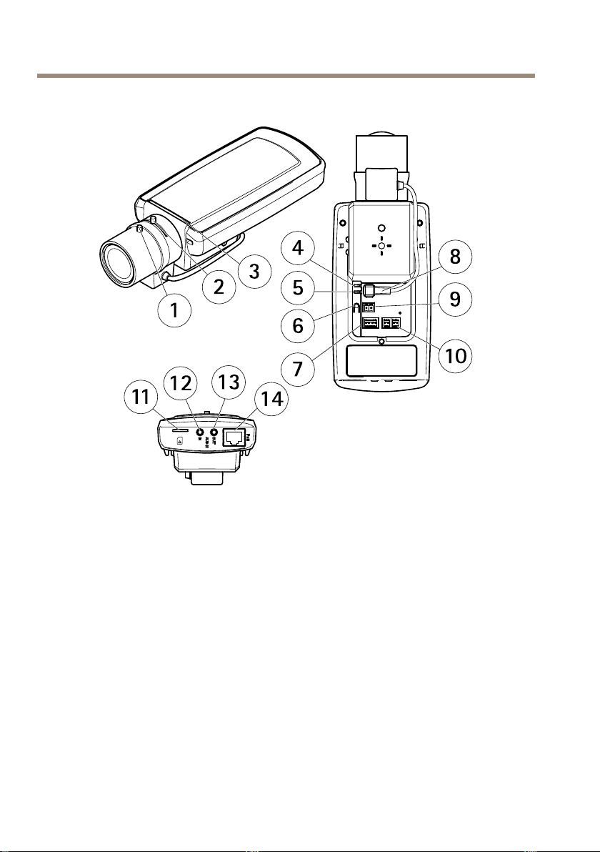
HardwareOverview
*Notusedforoutdoorvariants.
1
Focuspuller
2
Zoompuller
3
LEDindicator
4
PowerLED
5
NetworkLED
6
Controlbutton
7
I/Oterminalblock
8
Irisconnector
9
Powerconnector*
10
RS485/422
11
SDcardslot(microSD)
12
Audioin
13
Audioout
14
NetworkconnectorPoE
10
AXISP13-ESeries
1
2
3
4
11
5
6
7
8
9
10
12
13
14
15
16
17
18
ENGLISH
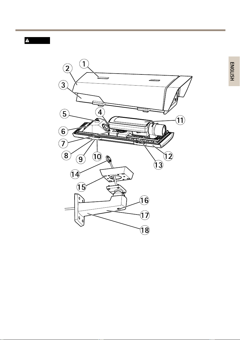
CAUTION
Riskofinjury.Theheatersinthehousingmaybehot.
1
Sunshieldadjustment
2
Sunshield
3
Topcover
4
Networkconnector(PoEIN)
5
Safetywiretab
6
Cablehole
7
Networkconnector(PoEOUT,connectedatdelivery)
8
Bottomcoverscrews(4x)
9
Cablecover
10
Cablecoverscrews(2x)
11
Networkcamera
11
AXISP13-ESeries
12
Bottomcover
13
Heaters
14
Bracketadapter
15
Bracketscrews(4x)
16
Bracketadjustmentscrew
17
Wallbracket
18
Alternativecablehole
LEDIndicators
Note
•TheStatusLEDcanbeconguredtobeunlitduringnormaloperation.Tocongure,go
toSetup>SystemOptions>Ports&Devices>LED.Seetheonlinehelpformore
information.
•TheStatusLEDcanbeconguredtoashwhileaneventisactive.
•TheStatusLEDcanbeconguredtoashforidentifyingtheunit.GotoSetup>System
Options>Maintenance.
StatusLED
GreenSteadygreenfornormaloperation.
Amber
NetworkLEDIndication
Green
Amber
UnlitNonetworkconnection.
PowerLEDIndication
Green
Amber
Indication
Steadyduringstartupandwhenrestoringsettings.
Steadyforconnectiontoa100Mbit/snetwork.Flashesfor
networkactivity.
Steadyforconnectiontoa10Mbit/snetwork.Flashesfor
networkactivity.
Normaloperation.
Flashesgreen/amberduringrmwareupgrade.
LEDIndicators
Note
ThehousingLEDreferredtointhetablebelowislocatedinthehousing.
12

AXISP13-ESeries
ENGLISH
HousingLED
(fanandheater)
Green
Flashinggreen
Indication
Normaloperation.
Singleash:Heatererror
Doubleash:Fanerror
Tripleash:Generalerror
Alarmeventswillbetriggeredthroughthecamera’sinputport.
ContactyourAxisresellerforinformationaboutsparepartsand
troubleshooting.
StatusLEDBehaviorforFocusAssistant
Color
Green
AmberThecamerahasbeenmoved,oranobjecthasbeenplacedinfrontofthelens.
RedThecamerahasbeenmoved,oranobjecthasbeenplacedinfrontofthelens.
Indication
FocusAssistantisenabled
Thelensisoptimallyadjusted
ExitandrestarttheFocusAssistant.
Thelensislessoptimallyadjusted.
ExitandrestarttheFocusAssistant.
Thelensispoorlyadjusted.
ConnectorsandButtons
Forspecicationsandoperatingconditions,seepage15.
NetworkConnector
RJ45EthernetconnectorwithPoweroverEthernet(PoE).
NO
TICE
NO NO
TICE TICE
Theproductshallbeconnectedusingashieldednetworkcable(STP).Allcablesconnecting
theproducttothenetworkshallbeintendedfortheirspecicuse.Makesurethatthe
networkdevicesareinstalledinaccordancewiththemanufacturer’sinstructions.For
informationaboutregulatoryrequirements,seeElectromagneticCompatibility(EMC)on
page2.
I/OConnector
Usewithexternaldevicesincombinationwith,forexample,tamperingalarms,motiondetection,
eventtriggering,timelapserecordingandalarmnotications.Inadditiontothe0VDCreference
pointandpower(DCoutput),theI/Oconnectorprovidestheinterfaceto:
13

AXISP13-ESeries
•Digitaloutput–ForconnectingexternaldevicessuchasrelaysandLEDs.Connected
devicescanbeactivatedbytheVAPIX®ApplicationProgrammingInterface,output
buttonsontheLiveViewpageorbyanActionRule.Theoutputwillshowasactive
(shownunderSystemOptions>Ports&Devices)ifthealarmdeviceisactivated.
•Digitalinput–Analarminputforconnectingdevicesthatcantogglebetweenanopen
andclosedcircuit,forexample:PIRs,door/windowcontacts,glassbreakdetectors,
etc.Whenasignalisreceivedthestatechangesandtheinputbecomesactive(shown
underSystemOptions>Ports&Devices).
Note
TheI/Oconnectorisconnectedtothehousing(fan/heater)ondelivery.Inthecaseofafan
orheatererror,aninputsignalwillbetriggeredinthecamera.Setupanactionruleinthe
cameratocongurewhichactionthesignalshalltrigger.Forinformationabouteventsand
actionrules,seetheUserManualavailableonwww.axis.com
AudioConnector
TheAxisproducthasthefollowingaudioconnectors:
•Audioin(pink)–3.5mminputforamonomicrophone,oraline-inmonosignal.
•Audioout(green)–3.5mmoutputforaudio(linelevel)thatcanbeconnectedto
apublicaddress(PA)systemoranactivespeakerwithabuilt-inamplier.Astereo
connectormustbeusedforaudioout.
Foraudioin,theleftchannelisusedfromastereosignal.
RS485/RS422Connector
TwoterminalblocksforRS485/RS422serialinterfaceusedtocontrolauxiliaryequipmentsuchas
pan-tiltdevices.
SDCardSlot
NO
TICE
NO NO
TICE TICE
•RiskofdamagetoSDcard.Donotusesharptoolsorexcessiveforcewheninserting
orremovingtheSDcard.
•Riskofdataloss.Topreventdatacorruption,theSDcardshouldbeunmountedbefore
removal.Tounmount,gotoSetup>SystemOptions>Storage>SDCardandclick
Unmount.
ThisproductsupportsmicroSD/microSDHC/microSDXCcards(notincluded).
ForSDcardrecommendations,seewww.axis.com
14

AXISP13-ESeries
ENGLISH
ControlButton
Forlocationofthecontrolbutton,seeHardwareOverviewonpage10.
Thecontrolbuttonisusedfor:
•EnablingtheFocusAssistant.PressandveryquicklyreleasetheControlbutton
•Resettingtheproducttofactorydefaultsettings.Seepage24.
•ConnectingtoanAXISVideoHostingSystemserviceorAXISInternetDynamicDNS
Service.Formoreinformationabouttheseservices,seetheUserManual.
Specications
OperatingConditions
ProductsTemperatureHumidity
AXISP1354-E
AXISP1357-E
ColdStartupDelaySwitch
ThehousingusedinthisAxisproductfeaturesArcticTemperatureControl,whichisenabledby
settingtheColdStartupDelayswitchtoI(ON).Whenenabled,thisfunctioncontrolswhenthe
camerarestartsafterapowercut,whentemperaturesarebelow0°C(32°F);thecameraisrst
heatedtoapproximately0°C(32°F)beforeitinitializes.Thispreventsdamagetocameramodels
thatincludemovingparts.
-30ºCto50ºC
(-22ºFto122ºF)withPoE,
downto-40ºC(-40ºF)withHighPoE
10-100%RH(condensing)
PowerConsumption
ProductsPoEHighPoE
AXISP1354-E
AXISP1357-E
max12.95W
IEEE802.3af/802.3atType1Class3
max25.5W
15

AXISP13-ESeries
123
Connectors
I/OConnector
4–pinterminalblock
Foranexamplediagram,seeConnectionDiagramsonpage18.
FunctionPinNotes
0VDC(-)
DCoutput
DigitalInput
Digital
Output
AudioConnector
3.5mmaudio
connectors(stereo)
AudioInput
AudioOutput
1
2
Canbeusedtopowerauxiliaryequipment.
Note:Thispincanonlybeusedaspowerout.
3
Connecttopin1toactivate,orleaveoating
(unconnected)todeactivate.
4
Connectedtopin1whenactivated,oating
(unconnected)whendeactivated.Ifused
withaninductiveload,e.g.arelay,adiode
mustbeconnectedinparallelwiththeload,
forprotectionagainstvoltagetransients.
1Tip2Ring
Microphone/Linein
Lineout(mono)
Specications
3.3VDC
Maxload=50mA
0tomax40VDC
0tomax40VDC,open
drain,100mA
3Sleeve
Ground
Ground
16
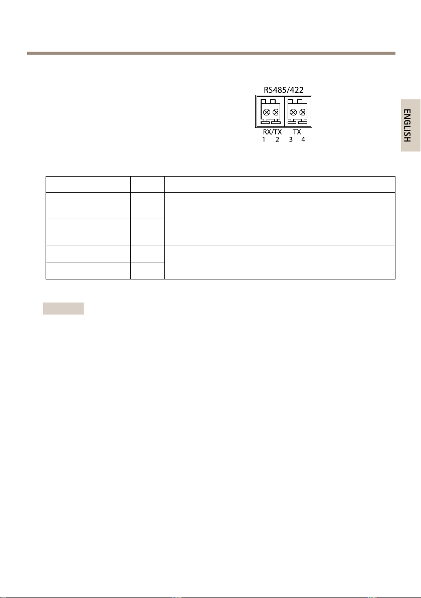
RS485/422Connector
RS485/422
1 2
RX/TX TX
3 4
ENGLISH
Two2-pinterminalblocksforRS485/RS422serial
interface.Theserialportcanbeconguredtosupport:
•Two-wireRS485halfduplex
•Four-wireRS485fullduplex
•Two-wireRS422simplex
•Four-wireRS422fullduplexpointtopoint
communication
FunctionPinNotes
RS485Balt
RS485/422RX(B)
RS485Aalt
RS485/422RX(A)
RS485/RS422TX(B)
RS485/RS422TX(A)
Important
Therecommendedmaximumcablelengthis30m(98.4ft).
1
2
3
4
RXpairforallmodes(combinedRX/TXfor2-wireRS485)
TXpairforRS422and4-wireRS485
AXISP13-ESeries
17
AXISP13-ESeries
1
2
3
4
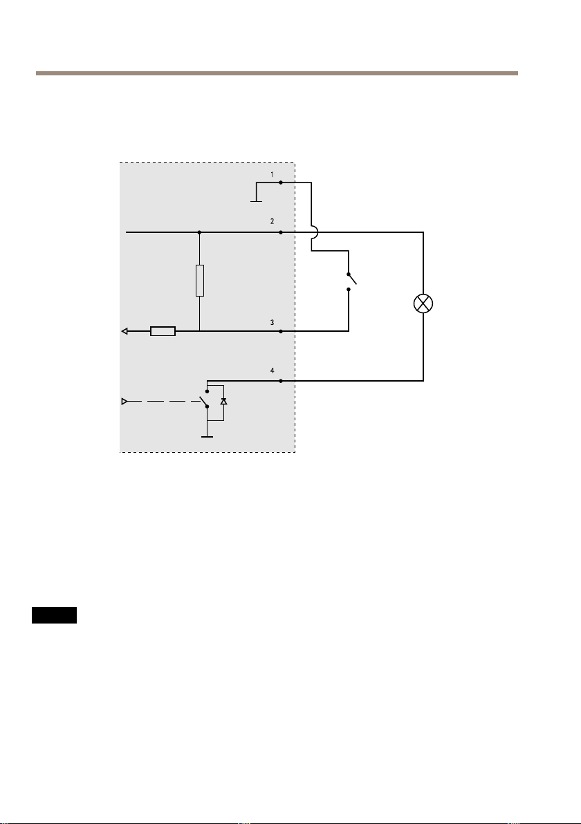
ConnectionDiagrams
I/OConnector
1
0VDC(-)
2
DCoutput3.3V,max50mA
3
Digitalinput0tomax40VDC
4
Digitaloutput0tomax40VDC,opendrain,100mA
InstalltheHardware
InstalltheWallBracket
NO
TICE
NO NO
TICE TICE
•Theweightofthecamerais3000g(6.6lb).Checkthatthematerialisstrongenoughto
supportthisweight.
•Alwaysuseashieldednetworkcable(STP)intendedforoutdoorusebetweenthe
Axisproductandtheendpointandensurethattheendpointisproperlygrounded.
InstallationsofAxisproductsusingashieldednetworkcable(STP)andaproperly
groundedendpointhavebeentestedtocomplywithindustryimmunitystandardlevels
suchassurgeprotection.Anyotherinstallationmethodwillvoidthewarrantyand
leavetheunitatarisk.
18
AXISP13-ESeries
4
3
2
1
ENGLISH
1.Usethesupplieddrilltemplatetoprepareawallorpoleforinstallationofthewall
bracket.
2.Routethenetworkcablethroughthewallbracket,andthroughthebracketadapter.
Leaveapproximately30cm(11.8in)ofcableforconnectingtothecamera.
3.Installthewallbracketonawall,ceiling,orpoleusingscrewsandplugsappropriatefor
thematerial(e.g.wood,metal,sheetrock,stone).
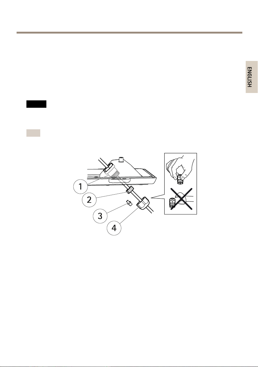
RoutetheNetworkCableThroughtheCableHole
NO
TICE
NO NO
TICE TICE
Usinganyotherthantheprovidedcableglandmaycausewatertoseepinanddamage
theproduct.Cablesmusthaveadiameterof4.0–5.5mm.
Note
Checkagainstthehardwareoverviewimage(seepage10)whilefollowingthestepsbelow.
1
Cablegland
2
Gasket
3
Plug(discard)
4
Cap
1.Loosenthecablecoverscrews;detachthecablecoverfromthebottomcover.
2.Removethecap,theplugandthegasketfromthecablegland.
3.Routethenetworkcablethroughthecap.
4.Slidethenetworkcablethroughtheslitonthegaskettoattachthegaskettothenetwork
cable.SeeConnectorsonpage16forinformationonnetworkcablerequirements.
5.Routethenetworkcablethroughthecablegland.
6.Pressthegasketintothecableglandandscrewthecaponrmly.
19
AXISP13-ESeries
1
2
3
4
5
6
7
8
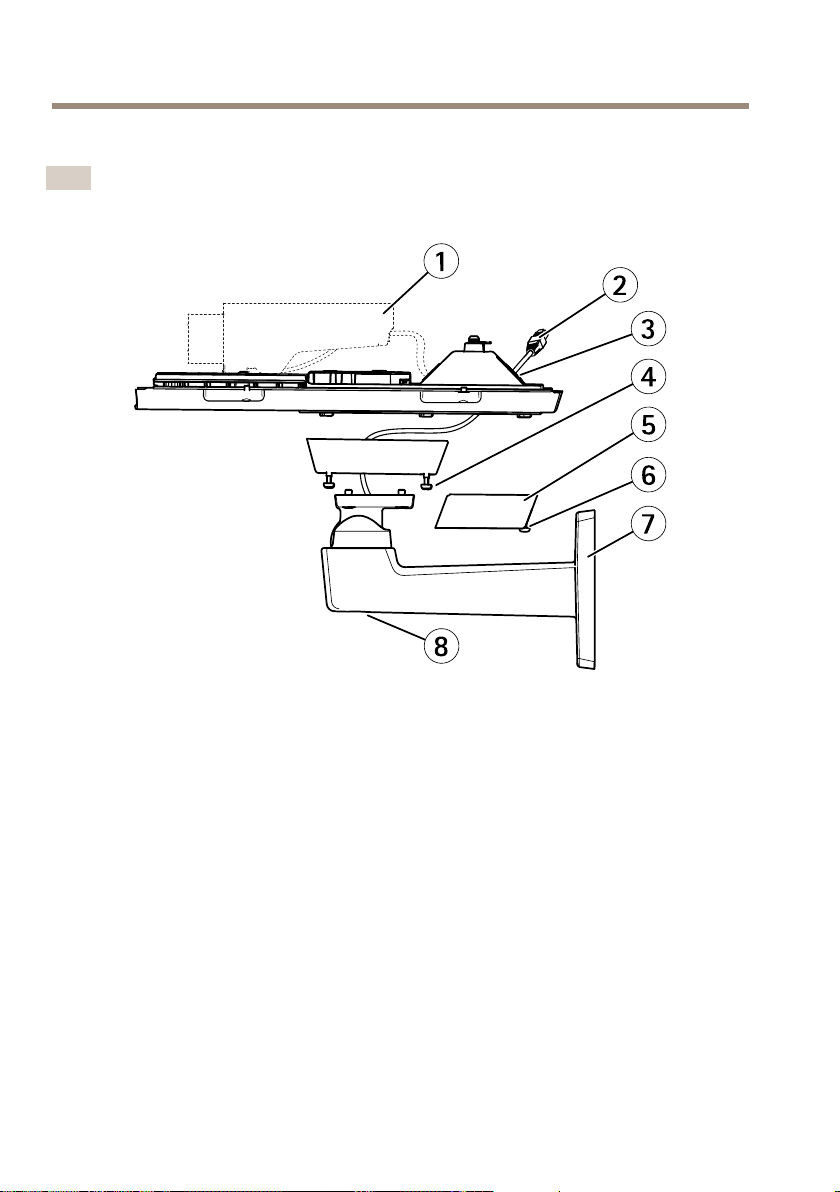
InstalltheCameraontheBracket
Note
TolocatethedifferentcomponentsseeillustrationsunderHardwareOverviewonpage10.
1
Axisnetworkcamera
2
Networkcable(routethroughwallbracket)
3
Cableholes
4
Bracketscrew(4x)
5
Cablecover
6
Cablecoverscrew(2x)
7
Wallbracket
8
Bracketadjustmentscrew
1.Installthecamerawiththebottomcoveronthebracketandtightenthebracketscrews.
2.Removethegasketfromoneoftheholesinthebottomcover.
3.Routethenetworkcablethroughtheholeandplugthecablegaskettothehole.
4.Connectthecables,seeConnecttheCables.
5.Takethetopcoverandattachthesafetywiretothetabonthebottomcover.
6.Loosenthebracketadjustmentscrewtopointthecameraintherightdirection.See
page22forinformationonhowtoviewthevideostream.
Adjustthefocus,seepage23.
20
AXISP13-ESeries
2
3
1
ENGLISH
7.Installthetopcover.Makesuretotightendiagonallyoppositebottomcoverscrewsa
fewturnsatatimeuntilallaretight.Thiswillhelpensurethatthebottomcovergasket
iscompressedevenly.Donottightenthescrewscompletelythersttime.
8.Installthecablecoverandtightenthecablecoverscrews.
9.Loosenthesunshieldadjustmentscrewsandadjustthesunshieldtothefrontposition.
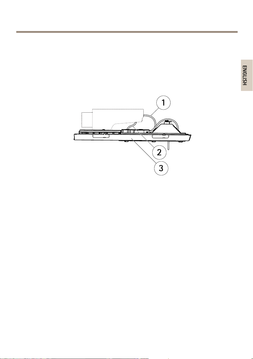
ConnecttheCables
1
Networkcables
2
I/Ocable
3
Bottomcover
21
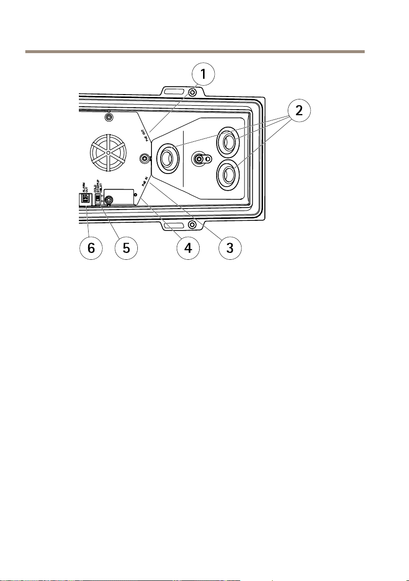
AXISP13-ESeries
1
456 3
2
1
Networkconnector(PoEOUT,connectedatdelivery)
2
Cableholes
3
Networkconnector(PoEIN)
4
LEDindicator
5
ArcticTemperatureControlswitch
6
Alarmoutput(connectedatdelivery)
1.OptionallyinsertanSDmemorycard(notincluded)intotheSDcardslot.Astandardor
highcapacitySDcardisrequiredtostoreimageslocallyinthecamera.
2.Optionallyconnectexternalinput/outputdevices.SeeConnectorsonpage16for
informationontheconnectorpins.SeeRoutetheNetworkCableThroughtheCableHole
onpage19forinformationonpreparingthenetworkcable.Routethecablesthrough
thecableholesintothebottomcoverandtothecamera.
3.Connectthecameratothenetworkusingashieldednetworkcableandusingthe
networkconnector(PoEIN)onthebottomcover.ThenetworkcableandtheI/Ocable
betweenthebottomcoverandthecamera,arealreadyconnectedatdelivery.
4.CheckthattheindicatorLEDsindicatethecorrectconditions.SeeLEDIndicatorson
page12forfurtherdetails.
AccesstheProduct
AXISIPUtilityandAXISCameraManagementarerecommendedmethodsforndingAxisproducts
onthenetworkandassigningthemIPaddressesinWindows®.Bothapplicationsarefreeandcan
bedownloadedfromwww.axis.com/techsup
22

AXISP13-ESeries
ENGLISH
Theproductcanbeusedwithmostoperatingsystemsandbrowsers.Therecommendedbrowsersare
•InternetExplorer
•Safari
•Chrome
Formoreinformationaboutusingtheproduct,seetheUserManualavailableatwww.axis.com
®
withOSX
TM
®
withWindows
®
orFirefox
®
withotheroperatingsystems.
®
AdjustFocus
Toadjustthezoomandfocusfollowtheseinstructions:
Note
•SetthefocusaspreciseaspossiblewiththefocuspullerorFocusAssistantbeforestarting
automaticnetuning.Usingthefocuspullernormallygivesthebestresult.
•Theirisshouldalwaysbeopenedtoitsmaximumwhilefocusing.Thisgivesthesmallest
depthofeldandthusthebestconditionsforcorrectfocusing.
1.Opentheproduct’shomepageandgotoSetup>BasicSetup>Focus.
2.UndertheBasictab,clickOpeniris.Ifthebuttonisinactivetheirisisalreadyopen.
3.Iffocushasbeensetbefore,clickResettoresetthebackfocus.
4.Loosenthezoomandfocuspullers(seeHardwareOverviewonpage10)onthelensby
turningthemcounter-clockwise.Movethepullerstosetzoomandfocusandcheckthe
qualityoftheimageintheimagewindow.
Ifthecameraismountedsothatonecannotlookattheimageandmovethepullers
atthesametime,usetheFocusAssistantinstead.See.
5.Loosenthezoompullerandthelockscrewforthefocusring(seeHardwareOverviewon
page10)onthelensbyturningthemcounter-clockwise.Movethezoompullerandthe
focusringtosetzoomandfocusandcheckthequalityoftheimageintheimagewindow.
Ifthecameraismountedsothatyoucannotlookattheimageandmovethezoompuller
andthefocusringatthesametime,usetheFocusAssistantinstead.See.
6.Re-tightenthezoomandfocuspullers.
7.OntheFocuspage,clickFine-tunefocusautomaticallyandwaituntilautomaticne
tuningiscompleted.
8.ClickEnableiris.Ifthebuttonisinactivetheirisisalreadyenabled.
9.Ifneeded,makefurtheradjustmentsundertheAdvancedtab.Seetheonlinehelpfor
moreinformation.
FocusAssistant
TofocususingtheFocusAssistant,followtheinstructionsinsteps1–3onpage23beforeyou
startwiththestepsbelow.
23

AXISP13-ESeries
Note
•Theviewinfrontofthecamerashouldnotbechangedduringfocusadjustment(steps5
and6).Ifthecameraismoved,orifangerorotherobjectisplacedinfrontofthelens,
steps3–7belowwillhavetoberepeated.
•Ifmovementsinfrontofthecameracannotbeavoided,theFocusAssistantshouldnot
beused.
•Ifthecontrolbuttonisnotreleasedwithintwoseconds,AXISDynamicDNSService
isenabledinsteadoftheFocusAssistant.
•Ifthecameraismountedsothatthecontrolbuttoncannotbeaccessed,youcanstilluse
theFocusAssistant.Followtheinstructionsbutmountthecameraafterstep4(pressing
thecontrolbutton)insteadandskipstep7.
1.Mountorplacethecamerasothatitcannotbemoved.
2.Loosenthezoompullerbyturningitanti-clockwise.Movethepullertosetthezoom
level.Retightenthezoompuller.
3.Setthecameratoitsextremedistant-focuspositionbylooseningthefocuspullerand
turningthefocusringfullyclockwise.
4.Pressandquicklyreleasethecontrolbutton.Whenthestatusindicatorashesgreen,the
FocusAssistantisenabled.Ifthestatusindicatorasheseitherredoramberbeforeyou
areabletoadjustthelens,skiptostep7toexittheFocusAssistantandrepeatsteps3–7.
5.Gentlyturnthefocusringanti-clockwiseuntilitstops.
6.Finally,turnthefocusringslowlyclockwiseuntilthestatusindicatorashesgreen
oramber(notred).
7.ToexittheFocusAssistant,pressthecontrolbutton.TheFocusAssistantisswitchedoff
automaticallyafter15minutes.
8.Retightenthefocuspuller.
9.OpentheLiveViewpageinthewebbrowserandcheckthequalityoftheimage.
10.Continuewithsteps6–8onpage23.
ResettoFactoryDefaultSettings
Important
Resettofactorydefaultshouldbeusedwithcaution.Aresettofactorydefaultwillreset
allsettings,includingtheIPaddress,tothefactorydefaultvalues.
Note
Theinstallationandmanagementsoftwaretoolsareavailablefromthesupportpages
onwww.axis.com/techsup
Toresettheproducttothefactorydefaultsettings:
24

AXISP13-ESeries
ENGLISH
1.Disconnectpowerfromtheproduct.
2.Pressandholdthecontrolbuttonandreconnectpower.SeeHardwareOverviewon
page10.
3.Keepthecontrolbuttonpressedfor15–30secondsuntilthestatusLEDindicatorashes
amber.
4.Releasethecontrolbutton.TheprocessiscompletewhenthestatusLEDindicatorturns
green.Theproducthasbeenresettothefactorydefaultsettings.IfnoDHCPserveris
availableonthenetwork,thedefaultIPaddressis192.168.0.90
5.Usingtheinstallationandmanagementsoftwaretools,assignanIPaddress,setthe
password,andaccessthevideostream.
6.Refocustheproduct.
Itisalsopossibletoresetparameterstofactorydefaultviathewebinterface.GotoSetup
>SystemOptions>Maintenance.
FurtherInformation
TheUserManualisavailableatwww.axis.com
Visitwww.axis.com/techsuptocheckifthereisupdatedrmwareavailableforyournetwork
product.Toseethecurrentlyinstalledrmwareversion,gotoSetup>About.
VisitAxislearningcenterwww.axis.com/academyforusefultrainings,webinars,tutorialsand
guides.
WarrantyInformation
ForinformationaboutAxis’productwarrantyandtheretorelatedinformation,see
www.axis.com/warranty/
25

26
AXISP13-ESeries
FRANÇAIS
Informationssurlasécurité
Lisezattentivementceguided'installationavantd'installerl'appareil.Conservezleguide
d'installationpourtouteréférenceultérieure.
Niveauxderisques
DANGER
Indiqueunesituationdangereusequi,siellen'estpasévitée,entraîneraledécèsoudes
blessuresgraves.
AVERTISSEMENT
Indiqueunesituationdangereusequi,siellen'estpasévitée,pourraitentraînerledécès
oudesblessuresgraves.
ATTENTION
Indiqueunesituationdangereusequi,siellen'estpasévitée,pourraitentraînerdes
blessureslégèresoumodérées.
VIS
A AAVIS VIS
Indiqueunesituationqui,siellen'estpasévitée,pourraitendommagerl'appareil.
Autresniveauxdemessage
Important
Indiquelesinformationsimportantes,nécessairespourassurerlebonfonctionnementde
l’appareil.
Note
Indiquelesinformationsutilesquipermettrontd’obtenirlefonctionnementoptimalde
l’appareil.
27

AXISP13-ESeries
Consignesdesécurité
AVERTISSEMENT
•LeproduitAxisdoitêtreinstalléparunprofessionnelhabilité.
VIS
A AAVIS VIS
•LeproduitAxisdoitêtreutiliséconformémentauxloisetrèglementationslocalesen
vigueur.
•ConserverceproduitAxisdansunenvironnementsecetventilé.
•NepasexposerceproduitAxisauxchocsouauxfortespressions.
•Nepasinstallerceproduitsurdessupports,surfacesoumursinstables.
•Utiliseruniquementdesoutilsrecommandéspourl'installationdel'appareilAxis.
L'applicationd'uneforceexcessivesurl'appareilavecdesoutilspuissantspourrait
l'endommager.
•Nepasutiliserdeproduitschimiques,desubstancescaustiquesoudenettoyants
pressurisés.
•Utiliserunchiffonpropreimbibéd'eaupurepourlenettoyage.
•Utiliseruniquementdesaccessoiresconformesauxcaractéristiquestechniquesduproduit.
IlspeuventêtrefournisparAxisouuntiers.
•UtiliseruniquementlespiècesderechangefourniesourecommandéesparAxis.
•Nepasessayerderéparerceproduitparvous-même.Contacterl'assistancetechnique
d'AxisouvotrerevendeurAxispourdesproblèmesliésàl'entretien.
•L'alimentationdoitêtrebranchéesuruneprisedecourantinstalléeàproximitéduproduit
etdoitêtrefacilementaccessible.
Transport
VIS
A AAVIS VIS
•LorsdutransportduproduitAxis,utilisezl'emballaged'origineouunéquivalentpour
éviterd'endommagerleproduit.
Batterie
LeproduitAxisutiliseunebatterieaulithiumBR/CR20323,0Vcommealimentationdeson
horlogeentempsréelinterne(RTC).Dansdesconditionsnormales,cettebatterieauneduréede
vieminimaledecinqans.
Silabatterieestfaible,lefonctionnementdel'horlogeentempsréelpeutêtreaffectéetentraîner
saréinitialisationàchaquemisesoustension.Unmessageenregistréapparaîtdanslerapportde
serveurduproduitlorsquelabatteriedoitêtreremplacée.Pourtoutcomplémentd'information
28

AXISP13-ESeries
FRANÇAIS
concernantlerapportdeserveur,reportez-vousauxpagesdeCongurationduproduitoucontactez
l'assistancetechniqued'Axis.
Labatteriedoitêtreremplacéeuniquementencasdebesoin,etpourcefaire,contactezl'assistance
techniqued'Axisàl'adressewww.axis.com/techsupetobtenirdel'aide.
AVERTISSEMENT
•Risqued'explosionsilabatterieestremplacéedefaçonincorrecte.
•Remplacez-launiquementparunebatterieidentiqueouunebatterierecommandéepar
Axis.
•Mettezaurebutlesbatteriesusagéesconformémentauxréglementationslocalesou
auxinstructionsdufabricantdelabatterie.
29

30
 Loading...