

Page 1

INSTALLATION GUIDE
AXIS M31-VE Network Camera Series
AXIS M3113-VE Network Camera
AXIS M3114-VE Network Camera
AXIS M3113-VE Nocap Network Camera
AXIS M3114-VE Nocap Network Camera
AXIS M3114-VE Nocap 2 MM Network Camera
ENGLISH DEUTSCH
FRAN
Ç
AIS
ITALIANO
ESPAÑOL
Page 2

About this Document
This document includes instructions for installing the
AXIS M31-VE Network Cameras on your network.
Previous experience of networking will be beneficial
when installing the product.
Legal Considerations
Video and audio surveillance can be prohibited by laws
that vary from country to country. Check the laws in
your local region before using this product for
surveillance purposes.
This product includes one (1) H.264 decoder license. To
purchase further licenses, contact your reseller.
Electromagnetic Compatibility (EMC)
This equipment generates, uses and can radiate radio
frequency energy and, if not installed and used in
accordance with the instructions, may cause harmful
interference to radio communications. However, there is
no guarantee that interference will not occur in a
particular installation.
If this equipment does cause harmful interference to
radio or television reception, which can be determined
by turning the equipment off and on, the user is
encouraged to try to correct the interference by one or
more of the following measures: Re-orient or relocate
the receiving antenna. Increase the separation between
the equipment and receiver. Connect the equipment to
an outlet on a different circuit to the receiver. Consult
your dealer or an experienced radio/TV technician for
help. Shielded (STP) network cables must be used with
this unit to ensure compliance with EMC standards.
USA - This equipment has been tested and found to
comply with the limits for a Class B computing device
pursuant to Subpart B of Part 15 of FCC rules, which are
designed to provide reasonable protection against such
interference when operated in a commercial
environment. Operation of this equipment in a
residential area is likely to cause interference, in which
case the user at his/her own expense will be required to
take whatever measures may be required to correct the
interference.
Canada - This Class B digital apparatus complies with
Canadian ICES-003.
Europe - This digital equipment fulfills the
requirements for radiated emission according to limit B
of EN55022, and the requirements for immunity
according to EN55024 residential and commercial
industry.
Japan - This is a class B product based on the standard
of the Voluntary Control Council for Interference from
Information Technology Equipment (VCCI). If this is used
near a radio or television receiver in a domestic
environment, it may cause radio interference. Install and
use the equipment according to the instruction manual.
Australia - This electronic device meets the
requirements of the Radio communications
(Electromagnetic Compatibility) Standard AS/NZS
CISPR22.
Korea -
ࢇЕɼࢽࡈ%ࢷળࢶଢԻ۰
࣯Իɼࢽ߾۰یࡈଜЕʨࡶּࢶࡳԻଜֲֻҘ
ࠇ߾۰یࡈଟܹݡТЬ
Equipment Modifications
This equipment must be installed and used in strict
accordance with the instructions given in the user
documentation. This equipment contains no
user-serviceable components. Unauthorized equipment
changes or modifications will invalidate all applicable
regulatory certifications and approvals.
Liability
Every care has been taken in the preparation of this
document. Please inform your local Axis office of any
inaccuracies or omissions. Axis Communications AB
cannot be held responsible for any technical or
typographical errors and reserves the right to make
changes to the product and documentation without
prior notice. Axis Communications AB makes no
warranty of any kind with regard to the material
contained within this document, including, but not
limited to, the implied warranties of merchantability
and fitness for a particular purpose. Axis
Communications AB shall not be liable nor responsible
for incidental or consequential damages in connection
with the furnishing, performance or use of this material.
RoHS
This product complies with both the European
RoHS directive, 2002/95/EC, and the Chinese
RoHS regulations, ACPEIP.
WEEE Directive
The European Union has enacted a Directive
2002/96/EC on Waste Electrical and Electronic
Equipment (WEEE Directive). This directive is
applicable in the European Union member
states.
The WEEE marking on this product (see right) or its
documentation indicates that the product must not be
disposed of together with household waste. To prevent
possible harm to human health and/or the environment,
the product must be disposed of in an approved and
environmentally safe recycling process. For further
information on how to dispose of this product correctly,
contact the product supplier, or the local authority
responsible for waste disposal in your area.
Business users should contact the product supplier for
information on how to dispose of this product correctly.
This product should not be mixed with other commercial
waste. For more information, visit
www.axis.com/techsup/commercial waste
Support
Should you require any technical assistance, please
contact your Axis reseller. If your questions cannot be
answered immediately, your reseller will forward your
queries through the appropriate channels to ensure a
rapid response. If you are connected to the Internet, you
can:
• download user documentation and firmware updates
• find answers to resolved problems in the FAQ database;
search by product, category, or phrases
• report problems to Axis support by logging in to your
private support area.
Page 3

Safeguards
Please read through this Installation Guide carefully before installing the product. Keep the Installation Guide
for further reference.
CAUTION!
• When transporting the Axis product, use the original packaging or equivalent to prevent damage to the
product.
• Store the Axis product in a dry and ventilated environment.
• Only use hand tools when installing the Axis product, the use of electrical tools or excessive force could
cause damage to the product.
• Do not use chemicals, caustic agents, or aerosol cleaners. Use a damp cloth for cleaning.
• Only use accessories and spare parts provided or recommended by Axis.
• Do not attempt to repair the product by yourself, contact Axis or your Axis reseller for service matters.
IMPORTANT!
• This Axis product must be used in compliance with local laws and regulations.
• If the installation requires IP66/IP67 classification, the attached network cable and IP66/IP67 classified
network connector must be used to create a water proof seal.
• The camera is designed for outdoor installation in a sheltered position and ceiling and wall mounting is recommended.
• For proper protection from water ingress, please check the following:
- The top cover must be properly closed
- The camera shall not be mounted outdoors facing the sky where the screws can collect water.
- Do not bend the network cable too close to the camera.
ENGLISH
Page 4

Page 5

AXIS M31-VE Network Camera Series Installation Guide Page 5
AXIS M31-VE Series
Installation Guide
This installation guide provides instructions for installing the following network cameras:
• AXIS M3113-VE
• AXIS M3114-VE
• AXIS M3113-VE Nocap
• AXIS M3114-VE Nocap
• AXIS M3114-VE Nocap 2 MM
For all other aspects of using the product, please see the user’s manual, available in the CD included
with this package, or available at www.axis.com/techsup
Installation steps
1. Check the package contents against the list below.
2. See Hardware overview. See page 6.
3. Install the hardware. See page 8.
4. Adjust the focus. See page 10.
5. Complete the installation. See page 10.
Package contents
Item Models/variants/notes
Network camera
AXIS M3113-VE, AXIS M3114-VE
AXIS M3113-VE Nocap, AXIS M3114-VE Nocap,
AXIS M3114-VE Nocap 2 MM
ENGLISH
Tools Adaptor with (2) lids
Lens tool
Top cover tool
Allen key
CD Installation and Management Software CD
Printed Materials AXIS M31-VE Network Camera Series Installation Guide (this
document)
Drill template
Extra serial number labels (2x)
Page 6

Page 6 AXIS M31-VE Network Camera Series Installation Guide
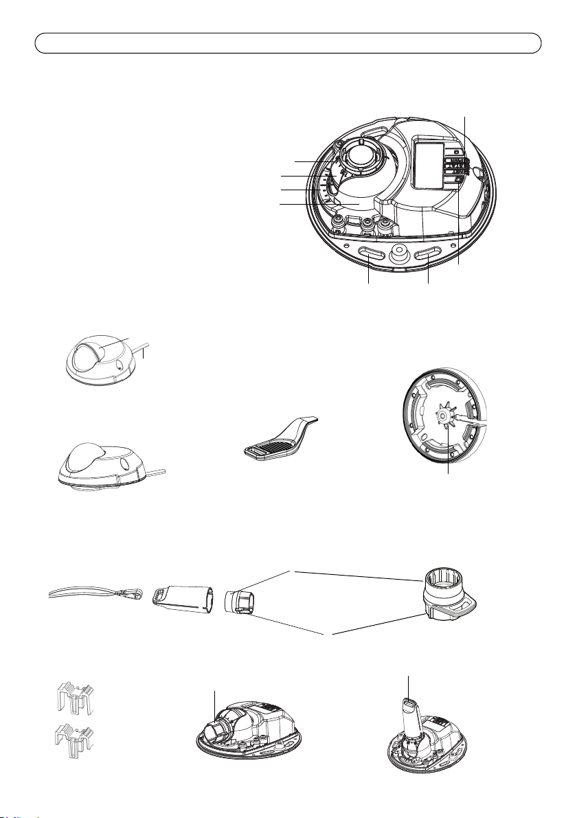
Lens holder
180° mark (top of image)
Optic holder
LED indicators
Lens tool
Transparent side
Black rubber side (for focus adjustment)
Ethernet cable
Control button
Optic mount
Use screws here to mount camera
(for image adjustment)
Lens tool for adjusting focus
to mounting surface
Adaptor
Lens tool for adjusting image
Top cover tool
Hole for mounting
camera on stand
AXIS M31-VE Nocap
AXIS M31-VE
Weather shield
Cable lids
Lens tool
(AXIS M3114-VE Nocap 2MM)
Hardware overview
Page 7

AXIS M31-VE Network Camera Series Installation Guide Page 7
LED indicators
LED Color Indication
Network
Status Green Steady green for normal operation.
Power Green Normal operation.
Green Steady for connection to a 100 Mbit/s network. Flashes for network activity.
Amber Steady for connection to 10 Mbit/s network. Flashes for network activity.
Unlit No network connection. Note: The Network LED can be configured to be unlit
during normal operation. To configure, go to Setup > System Options > LED set-
tings. See the online help files for more information.
Note: The Status LED can be configured to be unlit during normal operation, or to
flash only when the camera is accessed. To configure, go to Setup > System
Options > LED settings. See the online help files for more information.
Amber Steady during startup, during reset to factory default or when restoring settings.
Red Slow flash for failed upgrade.
Amber Flashes green/amber during firmware upgrade.
Unit connectors
Network connector - Male RJ-45 Ethernet connector for 10BaseT/100BaseTX with 3-meter cable.
Supports Power over Ethernet.
ENGLISH
Page 8

Page 8 AXIS M31-VE Network Camera Series Installation Guide
Cable lid
Cable lid
Cable slot
Install the hardware
1. Remove the top cover from the camera unit by
loosening the 2 screws. Then insert the top
cover tool into the slit in the bottom cover and
lift.
2. Depending on the kind of installation required, follow the appropriate instructions below.
Mount the camera without adaptor
1. Adjust the drill template on the mounting surface so the camera’s
lens faces the right direction, and drill four holes for the screws,
and one hole for the cable.
2. Align the screw slots in the camera with the screw holes in the
mounting surface, and attach the camera with 4 screws.
Note:
It is recommended that each screw head with the washer does not exceed
5mm in height and 7mm in diameter.
Do not use a countersunk screw head.
3. Attach the network cable to the PoE switch.
Mount camera with adaptor (cabling along the wall)
1. Place the adaptor on the mounting surface (wall or ceiling) and position the slot for the cable
where appropriate.
2. Fasten the adaptor with four screws appropriate to the surface material.
3. Draw the camera’s Ethernet cable along the cable slot
in the adaptor.
4. Press the cable lid appropriate for side cabling, into
the slot in the side of the adaptor.
5. Place the camera on the adaptor, and turn the camera
so the lens faces the correct direction.
6. Adjust so the screw slots on the camera are aligned
with the screw holes in the adaptor, and attach the 4
screws (torque < 2.5 Nm).
7. Attach the network cable to the PoE switch.
Page 9

AXIS M31-VE Network Camera Series Installation Guide Page 9
cable hole
cable lid
cable slot
Align ribs horizontally
line
line
Mount camera with adaptor (for cabling through the wall, and mounting on stand)
1. Slide the camera’s Ethernet cable through the
cable slot. Adjust the cable so it snaps into the
hole.
2. Press the appropriate cable lid into the slot in
the side of the adaptor.
3. Fasten the adaptor with four screws appropriate
to the surface material.
4. Follow steps 5-7 above.
Access the Axis Product
Use the tools provided on the Installation and Management Software CD to assign an IP address,
set the password and access the video stream.
Adjust the direction of the lens
Fit the lens tool to the lens holder, and adjust the position of the lens by pointing the lens tool
handle in the preferred direction (See illustration on page 6). This can be done vertically from 0 to
90 degrees (ensure weather shield is not blocking the view), and 30 degrees to the left or the right
on either side in increments of five.
The lens holder can also be rotated to adjust the image.
ENGLISH
Align the ribs in the lens tool horizontally so that the image is also aligned
horizontally.
Note:
The '0' mark on the lens holder indicates the bottom of
the image and the ‘180’ mark indicates the top, See
Hardware overview, on page 6. If the camera is mounted
upside down, adjust so the '0' mark is on top and the
'180' mark below the lens.
The line inside of the bottom of the optic holder should
be aligned with the line at the center of the optic mount.
Do not turn the lens more than one full turn.
Page 10

Page 10 AXIS M31-VE Network Camera Series Installation Guide
Fit black rubber side to adjust focus
lens tool
Adjust the focus
Pull the lens tool from the lens tool holder, turn it around and fit the black rubber side to the lens.
Adjust the focus. Check the image in the Live View page, and move the lens to the desired position
using the transparent side of the lens tool. See illustration under Hardware overview, on page 6.
After replacing the top cover, the image may appear slightly out of focus due to the optical effect
of the dome (especially in the case of tele/zoom lenses). To compensate, focus on an object slightly
closer than the intended area. If possible, position the top cover in front of the lens while adjusting
focus.
Complete the installation
To complete the installation, replace the top cover with care and tighten the captive screws. Ensure
that the rubber gasket in the top cover and the ridge it fits into in the bottom plate are dust-free.
Check the live view at this point to see if the weather shield on the top cover interferes with the
image. If it does, adjust the lens again as described above.
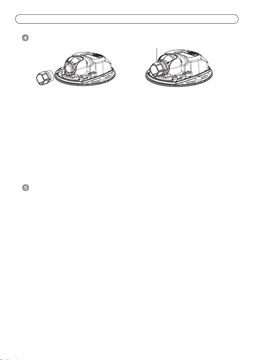
Changing the lens
To change the lens of the network camera:
1. Fit the black rubber side of the lens tool to the lens holder and unscrew the lens.
2. Remove the lens from the lens tool and fix the new lens to it.
3. Fit the new lens to the camera and tighten the lens into place.
4. Adjust the focus as described above.
Page 11

AXIS M31-VE Network Camera Series Installation Guide Page 11
Resetting to the Factory Default Settings
This will reset all parameters, including the IP address, to the factory default settings:
1. Disconnect power from the camera.
2. Remove the top cover by loosening the 2 captive screws.
3. Press and hold the Control button and reconnect power (see Hardware overview, on page 6).
4. Keep the Control button pressed for about 15 seconds until the Status indicator flashes amber.
5. Release the Control button. The process is complete after about 1 minute (when the Status
indicator turns green). The network camera has been reset to the factory default settings. The
default IP address is 192.168.0.90
6. Re-assign the IP address.
7. Refocus the camera.
It is also possible to reset parameters to factory default via the web interface. Go to Setup > System
Options > Maintenance.
Further information
The User Manual is available from the Axis Web site at www.axis.com
Visit Axis learning center www.axis.com/academy for useful trainings, webinars, tutorials and
guides.
ENGLISH
Tip!
Visit www.axis.com/techsup to check if there is updated firmware available for your network
product. To see the currently installed firmware version, see Setup > About.
Warranty
For information about Axis’ product warranty and thereto related information, see
www.axis.com/warranty
Page 12

Mesures de sécurité
Lisez attentivement le présent guide d’installation avant d’installer le produit. Conservez le guide d’installation
si vous souhaitez le consulter ultérieurement.
ATTENTION !
• Pour éviter d’endommager le produit Axis, utilisez l’emballage d’origine ou un équivalent pour le
transporter.
• Stockez le produit Axis dans un environnement sec et aéré.
• Utilisez uniquement des outils manuels pour l’installation du produit Axis, l’utilisation d’outils électriques
ou l’usage excessif de la force risque de l’endommager.
• N’utilisez ni produits chimiques, ni substances caustiques, ni nettoyeurs aérosol. Utilisez un linge humide
pour le nettoyage.
• Utilisez uniquement des accessoires et des pièces de rechange fournis ou recommandés par Axis.
• Ne tentez pas de réparer le produit vous-même, contactez Axis ou votre revendeur Axis pour tout problème
lié au service.
IMPORTANT !
• Ce produit Axis doit être utilisé conformément aux lois et réglementations locales en vigueur.
• Si l'installation requiert une classification IP66/IP67, le câble réseau et le connecteur réseau classifié IP66/
IP67 fournis doivent être utilisés pour créer un joint étanche à l'eau.
• Pour une bonne protection contre les infiltrations d'eau:
• Le capot supérieur doit être correctement fermé.
• Lorsqu'elle est monté sur un mur, le câble ne doit pas être orienté vers le haut dans le support de
fixation ce qui peut provoquer une infiltration d'eau dans la caméra. Il est recommandé que le câble
descende du support ou sur le côté.
• Ne pliez pas le câble réseau trop près de la caméra.
Page 13

Série des caméras réseau AXIS M31-VE Guide d’installation Page 13
Important !
Ce produit doit être utilisé
conformément aux lois et
réglementations locales en
vigueur.
Guide d’installation pour la série AXIS
M31-VE
Ce guide d’installation vous explique comment installer les caméras réseau suivantes :
• AXIS M3113-VE
• AXIS M3114-VE
• AXIS M3113-VE Nocap
• AXIS M3114-VE Nocap
• AXIS M3114-VE Nocap 2 MM
Pour toute autre question concernant l’utilisation du produit, reportez-vous au manuel de
l’utilisateur que vous trouverez sur le CD ci-joint ou sur le site www.axis.com/techsup
Procédure d’installation
1. Vérifiez le contenu de l’emballage en le comparant à la liste ci-dessous.
2. Description du matériel. Reportez-vous à la page 14.
3. Installation du matériel. Reportez-vous à la page 16.
4. Réglage de la mise au point. Reportez-vous à la page 18.
5. Fin de l’installation. Reportez-vous à la page 18.
Contenu de l’emballage
Élément Modèles/variantes/remarques
Caméra réseau
AXIS M3113-VE, AXIS M3114-VE
AXIS M3113-VE Nocap, AXIS M3114-VE Nocap, AXIS
M3114-VE Nocap 2 MM
FRANÇAIS
Outils Adaptateur à deux (2) couvercles, Outil de l’objectif, Outil du couvercle
CD Le CD d'installation et de gestion du logiciel, y compris les outils
Documentation imprimée Guide d’installation de la Série des caméras réseau AXIS M31-VE (le
supérieur, Clé hexagonale
d'installation et autre logiciel.
présent document)
Gabarit de perçage
Étiquettes de numéro de série supplémentaires
Document de garantie d’Axis
Page 14

Page 14 Série des caméras réseau AXIS M31-VE Guide d’installation
Porte-objectif
Marque « 180 »
Support optique
Voyants lumineux
Outil de l’objectif
Côté transparent
Côté noir en caoutchouc
Câble Ethernet
Bouton de commande
Monture optique
Utilisez les vis ici pour monter la caméra
(pour le réglage du champ de vision)
Outil de l’objectif pour le réglage de la mise au point
Adaptateur
Outil de l’objectif pour le réglage du champ de vision
Outil du couvercle supérieur
Trou pour le montage
de la caméra sur le support
AXIS M31-VE Nocap
AXIS M31-VE
Protection étanche
Couvercles de câble
(haut de l’image)
sur la surface de montage
Outil de l’objectif
(AXIS M3114-VE Nocap 2MM)
(pour le réglage de la mise au point)
Description du matériel
Page 15

Série des caméras réseau AXIS M31-VE Guide d’installation Page 15
Voyants lumineux
(DEL) Couleur Indication
Réseau Vert Continu en cas de connexion à un réseau de 100 Mbit/s. Clignote en cas d’activité
Orange Continu en cas de connexion à un réseau de 10 Mbit/s. Clignote en cas d’activité
Éteint Pas de connexion au réseau. Remarque : le voyant de réseau peut être configuré
État Vert Vert continu en cas de fonctionnement normal.
Orange Continu pendant le démarrage, la réinitialisation des paramètres d’usine ou la
Rouge Clignote lentement en cas d’échec de la mise à niveau.
Aliment
ation
Vert Fonctionnement normal.
Orange Clignote en vert/orange pendant la mise à niveau des micrologiciels.
réseau.
réseau.
pour être éteint au cours du fonctionnement normal. Pour ce faire, cliquez sur
Setup > System Options > LED settings (Configuration > Options système >
Paramètres des voyants). Reportez-vous à l’aide en ligne pour plus
d’informations.
Remarque : le voyant d’état peut être configuré pour être éteint pendant le
fonctionnement normal ou pour clignoter uniquement en cas d’accès à la caméra.
Pour ce faire, cliquez sur Setup > System Options > LED settings (Configuration
> Options système > Paramètres des voyants). Reportez-vous à l’aide en ligne
pour plus d’informations.
restauration des paramètres.
Connecteurs de l’unité
Connecteur réseau - Connecteur mâle Ethernet RJ-45 pour 10BaseT/100BaseTX avec câble de 3
mètres. Prend en charge l’alimentation par Ethernet (PoE).
FRANÇAIS
Page 16

Page 16 Série des caméras réseau AXIS M31-VE Guide d’installation
Couvercle de câble
Fente pour
de câble
Couvercle
câble
Installation du matériel
1. Enlevez le couvercle supérieur de la caméra en
desserrant les deux vis. Insérez ensuite l’outil
du couvercle supérieur dans la fente du
couvercle inférieur et soulevez-le.
2. Selon le type d’installation requise, suivez les instructions appropriées ci-dessous.
Monter la caméra sans l’adaptateur
1. Ajustez le gabarit de perçage sur la surface de montage de façon à
ce que l’objectif de la caméra soit dirigé dans la bonne direction,
puis percez quatre trous pour les vis et un trou pour le câble.
2. Alignez les emplacements pour les vis de la caméra avec les trous
faits dans la surface de montage, et fixez la caméra avec quatre
vis.
Remarque :
Chaque tête de vis avec rondelle doit mesurer 5 mm de haut et 7 mm de
diamètre au maximum.
N’utilisez pas de vis à tête fraisée.
3. Connectez le câble réseau au commutateur PoE.
Monter la caméra avec l’adaptateur (câbles le long du mur)
1. Placez l’adaptateur sur la surface de montage (mur ou plafond) et positionnez la fente pour le
câble à l’endroit approprié.
2. Fixez l’adaptateur avec quatre vis appropriées au matériau de la surface.
3. Faites glisser le câble Ethernet de la caméra le long de
la fente pour câble dans l’adaptateur.
4. Appuyez sur le couvercle de câble destiné au câblage
latéral pour l’insérer dans la fente située sur le côté de
l’adaptateur.
5. Placez la caméra sur l’adaptateur et tournez la caméra
pour que l’objectif soit dirigé dans la bonne direction.
6. Ajustez les fentes pour les vis de la caméra pour
qu’elles soient alignées avec les trous pour les vis de
l’adaptateur, puis fixez les quatre vis (couple < 2,5
Nm).
7. Connectez le câble réseau au commutateur PoE.
Page 17

Série des caméras réseau AXIS M31-VE Guide d’installation Page 17
Trou pour câble
Couvercle de câble
Fente pour câble
Alignez les nervures
horizontalement
Ligne
Ligne
Monter la caméra avec l’adaptateur (câbles dans le mur et montage sur support)
1. Faites glisser le câble Ethernet de la caméra
dans la fente pour câble. Ajustez le câble pour
qu’il s’insère dans le trou.
2. Appuyez sur le couvercle de câble approprié
pour l’insérer dans la fente sur le côté de
l’adaptateur.
3. Fixez l’adaptateur avec quatre vis appropriées
au matériau de la surface.
4. Suivez les étapes 5 à 7 ci-dessus.
Ajuster l’orientation de l’objectif
Insérez l’outil de l’objectif dans le porte-objectif et ajustez la position de l’objectif en orientant sa
poignée dans la direction souhaitée (voir l’illustration à la page 14). Cette opération peut se faire
verticalement de 0 à 90 degrés (assurez-vous que la protection étanche ne gène pas la vue) et de 30
degrés vers la gauche ou vers la droite de chaque côté par incrément de cinq.
Le porte-objectif peut également pivoter pour s’ajuster à l’image.
Alignez les nervures horizontalement sur le dispositif de l’objectif pour que
l’image soit aussi alignée horizontalement.
Remarque :
La marque « 0 » sur le porte-objectif indique le bas de
l’image et la marque « 180 » indique le haut de l’image,
consultez Description du matériel, à la page 14. Si la
caméra est montée à l’envers, ajustez-la de façon à ce
que la marque « 0 » soit en haut et la marque « 180 »
sous l’objectif.
La ligne à l’intérieur de la partie inférieure du porte-objectif doit être alignée avec la ligne au centre de
la monture optique.
Ne pas faire tourner l'objectif de plus d'un tour complet.
FRANÇAIS
Accéder au flux video
Utilisez le logiciel fourni sur le CD du logiciel d'installation et de gestion pour attribuer une
adresse IP, définir le mot de passe et accéder au flux vidéo.
Page 18
Page 18 Série des caméras réseau AXIS M31-VE Guide d’installation
Insérez le côté noir en caoutchouc pour régler la mise au point
Outil de l’objectif
Régler la mise au point
Enlevez l’outil de l’objectif du porte-objectif, retournez-le et intégrez le côté noir en caoutchouc à
l’objectif. Réglez la mise au point. Vérifiez l’image dans la page Live View (Vue en direct) et placez
l’objectif dans la position souhaitée, en utilisant le côté transparent du l’outil de l’objectif. Voir
l’illustration dans Description du matériel, à la page 14.
Après avoir replacé le couvercle supérieur, l’image peut être légèrement floue en raison de l’effet
optique du dôme (particulièrement dans le cas d’objectifs avant/zoom). Pour compenser ce défaut,
effectuez la mise au point sur un objet légèrement plus proche que la zone cible. Si possible, placez
le couvercle supérieur devant l’objectif tout en réglant la mise au point.
Fin de l’installation
Pour terminer l’installation, replacez le couvercle supérieur avec précaution et serrez les vis
imperdables. Assurez-vous que le joint en caoutchouc du couvercle supérieur et la strie dans
laquelle il s’emboîte dans le plateau inférieur ne présentent aucune poussière.
Vérifiez alors la vue en temps réel pour voir si la protection étanche sur le couvercle supérieur
interfère avec l’image. Si tel est le cas, réglez de nouveau l’objectif comme indiqué plus haut.
Remplacement de l’objectif
Pour remplacer l’objectif de la caméra réseau :
1. Ajustez le côté noir en caoutchouc de l’outil de l’objectif au porte-objectif et dévissez l’objectif.
2. Enlevez l’objectif de l‘outil de l’objectif et fixez-y le nouvel objectif.
3. Ajustez le nouvel objectif à la caméra et serrez l’objectif pour le maintenir solidement en place.
4. Réglez la mise au point comme indiqué plus haut.
Page 19

Série des caméras réseau AXIS M31-VE Guide d’installation Page 19
Rétablissement des paramètres d’usine
Procédez comme suit pour rétablir les paramètres par défaut définis en usine et réinitialiser
l’adresse IP :
1. Mettez la caméra hors tension.
2. Enlevez le couvercle supérieur en desserrant les deux vis imperdables.
3. Maintenez le bouton de commande enfoncé tout en remettant l’appareil sous tension
(reportez-vous à la Description du matériel, à la page 14).
4. Maintenez le bouton de commande enfoncé jusqu’à ce que le voyant d’état devienne l’orange
(cela prend environ 15 secondes).
5. Relâchez le bouton de commande. Le processus se termine après environ 1 minute (lorsque le
voyant d’état devient vert). Les paramètres d’usine de la caméra réseau ont été rétablis.
L’adresse IP par défaut est 192.168.0.90
6. Attribuez à nouveau l’adresse IP.
7. Effectuez de nouveau la mise au point de la caméra.
Il est également possible de rétablir les paramètres d’usine à partir de l’interface Web. Cliquez sur
Setup > System Options > Maintenance (Configuration > Options système > Maintenance).
Plus d’informations
Le manuel de l’utilisateur est disponible sur le site web d’Axis à l’adresse www.axis.com
Pour en savoir plus sur les produits et les technologies d’Axis, rendezvous sur
ww.axis.com/academy, le centre de formation mondial pour la vidéo sur IP.
FRANÇAIS
Tip!
Consultez le site www.axis.com/techsup pour vérifier si des mises à jour des micrologiciels sont
disponibles pour votre produit Axis. Pour connaître la version du micrologiciel actuellement
installée, reportezvous à la page Setup > About (Configuration > À propos de) dans votre interface
web.
Garantie
Pour plus d'informations sur la garantie des produits Axis et des informations générales relatives à
celle-ci merci de consulter le site www.axis.com/warranty
Page 20

Sicherheitsvorkehrungen
Bitte lesen Sie zunächst diese Installationsanleitung vollständig durch, bevor Sie mit der Installation Ihres
Produkts beginnen. Halten Sie die Installationsanleitung bereit, falls Sie darauf zurückgreifen müssen.
VORSICHT!
• Transportieren Sie das Axis-Produkt nur in der Originalverpackung bzw. in einer vergleichbaren Verpackung,
damit das Produkt nicht beschädigt wird.
• Lagern Sie das Axis-Produkt in einer trockenen und belüfteten Umgebung.
• Verwenden Sie keine elektrischen Werkzeuge zur Montage des Axis-Produkts, da diese das Produkt
beschädigen könnten.
• Verwenden Sie keine chemischen, ätzenden oder Aerosol-Reinigungsmittel. Verwenden Sie zur Reinigung
ein feuchtes Tuch.
• Verwenden Sie nur Zubehör und Ersatzteile, die von Axis empfohlen bzw. bereitgestellt wurden.
• Versuchen Sie nicht, das Produkt selbst zu reparieren. Wenden Sie sich bei Service-Angelegenheiten an Axis
oder an Ihren Axis-Händler.
WICHTIG!
• Verwenden Sie dieses Axis-Produkt unter Beachtung der geltenden rechtlichen Bestimmungen.
• Wenn das Produkt die IP66/IP67 Klassifizierung benötigt, dann muss das fest montierte Netzwerkkabel
sowie der IP66/IP67 klassifizierte Netzwerkstecker verwendet werden, damit eine wasserdichte Verbindung
hergestellt wird.
• Um das Eindringen von Wasser zu vermeiden:
• Schließen Sie die obere Abdeckung korrekt.
• Wenn die Kamera an einer Wand montiert wird, dann soll das Kabel nicht von oben zugeführt
werden, da entlang des Kabels Wasser in die Kamera eindringen kann. Es wird empfohlen, dass das
Kabel entweder nach unten oder zur Seite hin weggeführt wird.
• Vermeiden Sie das Netzwerkkabel sehr nahe an der Kamera abzuwinkeln.
Page 21

AXIS M31-VE Netzwerk-Kamera-Serie Installationsanleitung Seite 21
Wichtig!
Verwenden Sie dieses Produkt
unter Beachtung der geltenden
rechtlichen Bestimmungen.
Installationsanleitung für die AXIS
M31-VE Serie
In dieser Anleitung wird die Installation der folgenden Netzwerk-Kameras beschrieben:
• AXIS M3113-VE
• AXIS M3114-VE
• AXIS M3113-VE Nocap
• AXIS M3114-VE Nocap
• AXIS M3114-VE Nocap 2 MM
Alle weiteren Hinweise zur Verwendung des Produkts finden Sie im Benutzerhandbuch, das auf der
mitgelieferten CD oder auf unserer Website unter „www.axis.com/techsup“ zur Verfügung steht.
Installationsschritte
1. Prüfen Sie, ob alle in der nachfolgenden Liste aufgeführten Komponenten vorhanden sind.
2. Sehen Sie sich die Hardwareübersicht an. Siehe Seite 22.
3. Installieren Sie die Hardware. Siehe Seite 24.
4. Stellen Sie die Bildschärfe ein. Siehe Seite 27.
5. Schließen Sie die Installation ab. Siehe Seite 27.
Inhalt des Produktpakets
Komponente Modelle/Varianten/Anmerkungen
Netzwerk-Kamera
AXIS M3113-VE, AXIS M3114-VE
AXIS M3113-VE Nocap, AXIS M3114-VE Nocap, AXIS
M3114-VE Nocap 2 MM
DEUTSCH
Tools Adapter mit (2) Klemmen
Objektivwerkzeug
Werkzeug für obere Abdeckung
Inbusschlüssel
CD-ROM Installations- und Verwaltungssoftware-CD, einschl. Installationstools
und anderer Software
Gedruckte Dokumente AXIS M31-VE Netzwerk-Kamera-Serie Installationsanleitung (dieses
Dokument)
Bohrschablone
Zusätzliche Aufkleber mit Seriennummer
Axis-Garantieerklärung
Page 22

Seite 22 AXIS M31-VE Netzwerk-Kamera-Serie Installationsanleitung
Objektivhalter
180°-Markierung
Optikhalter
LED-Anzeigen
Objektivwerkzeug
Transparente Seite
Schwarze Gummiseite
Ethernet-Kabel
Steuertaste
Optikanschluss
Bringen Sie die Schrauben hier an, um die Kamera
(für die Bildanpassung)
Objektivwerkzeug für die Einstellung der Bildschärfe
Adapter
Objektivwerkzeug für die Bildanpassung
Werkzeug für obere Abdeckung
Öffnung zur Montage der
Kamera auf einem Standfuß
AXIS M31-VE Nocap
AXIS M31-VE
Wetterschutz
Kabelklemmen
(Bildoberseite)
an der Montageoberfläche zu befestigen
Objektivwerkzeug
(AXIS M3114-VE Nocap 2MM)
(für das Einstellen der Bildschärfe)
Hardwareübersicht
Page 23

AXIS M31-VE Netzwerk-Kamera-Serie Installationsanleitung Seite 23
LED-Anzeigen
LED Farbe Bedeutung
Netzwerk
Status Grün Leuchtet bei Normalbetrieb konstant grün.
Betriebs
anzeige
Grün Leuchtet dauerhaft bei Verbindung mit einem 100-MBit/s-Netzwerk. Blinkt bei
Gelb Leuchtet dauerhaft bei Verbindung mit einem 10-MBit/s-Netzwerk. Blinkt bei
Leuchtet
nicht
Gelb Leuchtet konstant beim Einschalten und beim Wiederherstellen der
Rot Blinkt langsam bei Aktualisierungsfehler.
Grün Normaler Betrieb.
Gelb Blinkt grün/gelb während Firmware-Aktualisierung.
Netzwerkaktivität.
Netzwerkaktivität.
Keine Netzwerkverbindung vorhanden. Hinweis: Die Netzwerk-LED kann so
konfiguriert werden, dass sie bei normalem Betrieb nicht leuchtet. Diese
Einstellung können Sie unter „Setup > System Options > LED settings“ (Setup >
Systemoptionen > LED-Einstellungen) vornehmen. Weitere Informationen
hierzu finden Sie in der Online-Hilfe.
Hinweis: Die Status-LED kann so konfiguriert werden, dass sie bei normalem
Betrieb nicht leuchtet oder nur dann blinkt, wenn auf die Kamera zugegriffen
wird. Diese Einstellung können Sie unter „Setup > System Options > LED
settings“ (Setup > Systemoptionen > LED-Einstellungen) vornehmen. Weitere
Informationen hierzu finden Sie in der Online-Hilfe.
Werkseinstellungen bzw. von vorherigen Einstellungen.
Geräteanschlüsse
Netzwerkanschluss - RJ-45-Ethernet-Stecker für 10BaseT/100BaseTX mit 3-Meter-Kabel.
Unterstützt Power over Ethernet.
DEUTSCH
Page 24

Seite 24 AXIS M31-VE Netzwerk-Kamera-Serie Installationsanleitung
Installieren der Hardware
1. Entfernen Sie die obere Abdeckung von der
Kameraeinheit, indem Sie zunächst die beiden
Schrauben lösen. Schieben Sie anschließend
das Werkzeug für die obere Abdeckung in den
Spalt der unteren Abdeckung und heben Sie diese an.
2. Führen Sie abhängig von der erforderlichen Installationsart die entsprechenden unten
stehenden Schritte aus.
Montage der Kamera ohne Adapter
1. Richten Sie die Bohrschablone auf der Montageoberfläche so aus,
dass das Objektiv der Kamera in die richtige Richtung zeigt, und
bohren Sie vier Löcher für die Schrauben sowie ein Loch für das
Kabel.
2. Richten Sie die Aussparungen für die Schrauben in der Kamera auf
die Schraubenlöcher in der Montageoberfläche aus und befestigen
Sie die Kamera mit vier Schrauben.
Hinweis:
Die Größe der Schraubenköpfe sollte zusammen mit der Unterlegscheibe
eine Höhe von 5 mm und einen Durchmesser von 7mm nicht überschreiten.
Verwenden Sie keine Senkkopfschrauben.
3. Schließen Sie das Netzwerkkabel am PoE-Switch an.
Montage der Kamera mit Adapter (Verkabelung entlang der Wand)
1. Platzieren Sie den Adapter auf der Montageoberfläche (Wand oder Decke) und positionieren Sie
die Aussparung für das Kabel an der richtigen Stelle.
2. Befestigen Sie den Adapter mit vier für das Oberflächenmaterial geeigneten Schrauben.
Page 25

AXIS M31-VE Netzwerk-Kamera-Serie Installationsanleitung Seite 25
Kabelklemme
Kabelklemme
Kabelaussparung
Kabeldurchführung
Kabelklemme
Kabelaussparung
3. Ziehen Sie das Ethernet-Kabel entlang der
Kabelaussparung in den Adapter.
4. Drücken Sie die Kabelklemme für die seitliche
Verkabelung in die seitliche Öffnung des Adapters.
5. Platzieren Sie die Kamera auf dem Adapter und drehen
Sie sie, bis das Objektiv in die richtige Richtung zeigt.
6. Richten Sie die Aussparungen für die Schrauben in der
Kamera auf die Schraubenlöcher im Adapter aus und
bringen Sie die vier Schrauben an (Drehmoment < 2,5
Nm).
7. Schließen Sie das Netzwerkkabel am PoE-Switch an.
Montage der Kamera mit Adapter (zur
Verkabelung durch die Wand und Montage auf
dem Standfuß)
1. Führen Sie das Ethernet-Kabel der Kamera durch
die Kabelaussparung. Drücken Sie das Kabel in
die Kabeldurchführung.
2. Drücken Sie die entsprechende Kabelklemme in
die seitliche Öffnung des Adapters.
3. Befestigen Sie den Adapter mit vier für das
Oberflächenmaterial geeigneten Schrauben.
4. Fahren Sie mit den Schritten 5 bis 7 oben fort.
DEUTSCH
Page 26

Seite 26 AXIS M31-VE Netzwerk-Kamera-Serie Installationsanleitung
Rippen horizontal
ausrichten
Linie
Linie
Einstellen der Objektivrichtung
Bringen Sie das Objektivwerkzeug am Objektivhalter an und passen Sie die Position des Objektivs
an, indem Sie den Griff des Objektivwerkzeugs in die gewünschte Richtung bewegen (siehe
Abbildung auf Seite 22). Der Griff des Objektivwerkzeugs kann in 5-Grad-Schritten vertikal in einem
Winkel von 0 bis 90 Grad (stellen Sie sicher, dass die Sicht nicht durch den Wetterschutz versperrt
wird) sowie auf beiden Seiten um 30 Grad nach links und rechts bewegt werden.
Darüber hinaus kann der Objektivhalter zur Anpassung des Bilds gedreht
werden.
Richten Sie die Rippen im Objektivwerkzeug horizontal aus, sodass das Bild
ebenfalls horizontal ausgerichtet ist.
Hinweis:
Die „0“-Markierung am Objektivhalter gibt die
Unterseite des Bilds an und die „180“-Markierung die
Oberseite. Siehe Hardwareübersicht, auf Seite 22. Wenn
die Kamera über Kopf montiert wird, muss sich die
„0“-Markierung auf der Oberseite und die
„180“-Markierung unter dem Objektiv befinden.
Die Linie innerhalb der Unterseite des Optikhalters muss auf die Linie in der Mitte des Optikanschlusses
ausgerichtet sein.
Drehen Sie die Linse nicht um mehr als eine volle Drehung.
Zugriff auf den Videostream
Bitte verwenden Sie die auf der beigefügten Installations- und Management-Software-CD
enthaltenen Werkzeuge, um dem Produkt eine IP-Adresse zuzuweisen und auf den Videostream
zuzugreifen. Diese Information finden Sie auch auf den Support-Seiten unter
"www.axis.com/techsup"
Page 27

AXIS M31-VE Netzwerk-Kamera-Serie Installationsanleitung Seite 27
Befestigen der schwarzen Gummiseite zum Einstellen des Fokus
Objektivwerkzeug
Einstellen der Bildschärfe
Ziehen Sie das Objektivwerkzeug aus dem Objektivwerkzeughalter, drehen Sie es um und befestigen
Sie die schwarze Gummiseite am Objektiv. Stellen Sie die Bildschärfe ein. Überprüfen Sie das Bild
auf der Seite Live View (Live-Ansicht) und bewegen Sie das Objektiv mithilfe der transparenten
Seite des Objektivwerkzeugs in die gewünschte Position. Siehe Abbildung unter Hardwareübersicht,
auf Seite 22.
Nachdem die obere Abdeckung wieder angebracht wurde, kann das Bild aufgrund des optischen
Effekts der Kuppel (insbesondere bei Tele-/Zoom-Objektiven) leicht unscharf erscheinen. Um diesen
Effekt auszugleichen, stellen Sie die Kamera auf ein Objekt scharf, das etwas näher als der zu
erfassende Bereich liegt. Positionieren Sie die obere Abdeckung beim Einstellen der Bildschärfe
nach Möglichkeit vor dem Objektiv.
DEUTSCH
Installation abschließen
Um die Installation abzuschließen, setzen Sie die obere Abdeckung vorsichtig wieder auf die
Kameraeinheit und ziehen Sie die unverlierbaren Schrauben fest. Stellen Sie sicher, dass die
Gummidichtung in der oberen Abdeckung und die Kante in der Bodenplatte, mit der sie abschließt,
frei von Staub sind.
Überprüfen Sie an dieser Stelle in der Live-Ansicht, ob der Wetterschutz auf der oberen Abdeckung
das Sichtfeld beeinträchtigt. Ist dies der Fall, wiederholen Sie die oben beschriebenen Schritte und
passen Sie das Objektiv erneut an.
Wechseln des Objektivs
So wechseln Sie das Objektiv der Netzwerk-Kamera:
1. Befestigen Sie die schwarze Gummiseite des Objektivwerkzeugs am Objektivhalter und
schrauben Sie das Objektiv ab.
2. Entfernen Sie das Objektiv vom Objektivwerkzeug und befestigen Sie das neue Objektiv daran.
3. Befestigen Sie das neue Objektiv an der Kamera, indem Sie es festschrauben.
4. Stellen Sie die Bildschärfe ein, wie oben beschrieben.
Page 28

Seite 28 AXIS M31-VE Netzwerk-Kamera-Serie Installationsanleitung
Wiederherstellen der werkseitigen Standardeinstellungen
Gehen Sie wie folgt vor, um sämtliche Parameter einschließlich der IP-Adresse auf die werkseitigen
Standardeinstellungen zurückzusetzen:
1. Trennen Sie die Kamera von der Stromversorgung.
2. Entfernen Sie die obere Abdeckung, indem Sie die beiden unverlierbaren Schrauben lösen.
3. Halten Sie die Steuertaste gedrückt und stellen Sie die Stromversorgung wieder her (siehe
„Hardwareübersicht“ auf Seite 22).
4. Halten Sie die Steuertaste etwa 15 Sekunden gedrückt, bis die Statusanzeige gelb blinkt.
5. Lassen Sie die Steuertaste los. Der Vorgang ist nach etwa 1 Minute abgeschlossen (die
Statusanzeige wird grün). Die Netzwerk-Kamera wurde auf die werkseitigen
Standardeinstellungen zurückgesetzt. Die Standard-IP-Adresse lautet 192.168.0.90.
6. Weisen Sie die IP-Adresse erneut zu.
7. Führen Sie die Fokussierung der Kamera erneut durch.
Die Parameter können auch über die Weboberfläche auf die werkseitigen Einstellungen
zurückgesetzt werden. Wählen Sie „Setup > System Options > Maintenance“ (Setup >
Systemoptionen > Wartung).
Weitere Informationen
Das Benutzerhandbuch steht auf der Website von Axis unter „www.axis.com“ zur Verfügung. Um
mehr über Produkte und Technologien von Axis zu erfahren, besuchen Sie uns unter
„www.axis.com/academy“, dem globalem Lernzentrum für Netzwerk- Video.
Tip!
Unter „www.axis.com/techsup“ finden Sie Firmware-Aktualisierungen für Ihr Axis-Produkt.
Informationen zur aktuell installierten finden Sie in Ihrer Weboberfläche unter „Setup“>„About“
(Info).
Garantie
Die Garantiebedingungen für Axis Produkte sowie weitere Informationen zum Thema Garantie
finden Sie unter www.axis.com/warranty
Page 29

Page 30

Precauzioni
Leggere per intero e con attenzione questa Guida all'installazione prima di installare il prodotto. Conservare la
Guida all'installazione per ulteriori riferimenti.
ATTENZIONE!
• Quando si trasporta un prodotto Axis, utilizzare l'imballo originale o un imballo equivalente per evitare
danni al prodotto.
• Conservare il prodotto Axis in un ambiente asciutto e ventilato.
• Per l'installazione del prodotto Axis, utilizzare solo attrezzi manuali, l'utilizzo di utensili elettrici o
l'applicazione di una forza eccessiva potrebbero danneggiare il prodotto.
• Non utilizzare sostanze chimiche, agenti caustici o detergenti aerosol. Utilizzare un panno umido per la
pulizia.
• Utilizzare solo accessori e parti di ricambio forniti o consigliati da Axis.
• Non tentare di riparare da soli il prodotto, ma contattare Axis o il rivenditore Axis per qualsiasi argomento
relativo all'assistenza tecnica.
IMPORTANTE!
• Questo prodotto Axis deve essere utilizzato in conformità alle leggi e alle regolamentazioni locali.
• Per utilizzare questo prodotto Axis all'esterno, è necessario installarlo in un alloggiamento per esterni
approvato.
• Il prodotto Axis deve essere installato da un tecnico qualificato. Osservare le disposizioni nazionali e locali
per l'installazione.
• Se l'istallazione richiede certificazione di classe IP66/67, sarà necessario utilizzare gli appositi connettori in
dotazione per assicurare una completa protezione da infiltrazioni.
• Affinchè l'unità sia protetta da infiltrazioni assicurarsi che:
• Il coperchio superiore sia ermeticamente chiuso.
• Quando montata a muro, i cavi non provengano dall'alto, per evitare gocciolamento verso la
telecamera. Si raccomanda che il cablaggio scenda dalla telecamera o sia disposto lateralmente.
• Non piegare il cavo di rete in prossimitità della telecamera.
Page 31

Guida all'installazione di Telecamere di rete serie AXIS M31-VE Pagina 31
Importante!
Questo prodotto deve essere
usato in conformità alle leggi e
ai regolamenti locali.
Guida all'installazione della serie AXIS
M31-VE
Nel presente documento vengono fornite le istruzioni per installare le seguenti telecamere di rete:
• AXIS M3113-VE
• AXIS M3114-VE
• AXIS M3113-VE Nocap
• AXIS M3114-VE Nocap
• AXIS M3114-VE Nocap 2 MM
Per ulteriori informazioni sull’utilizzo del prodotto, consultare la guida per l'utente disponibile sul
CD incluso nella confezione o all’indirizzo www.axis.com/techsup
Procedura di installazione
1. Controllare il contenuto della confezione con l'elenco che segue.
2. Vedere la Panoramica dell’hardware. Vedere pagina 32.
3. Installazione dell'hardware. Vedere pagina 34.
4. Regolare la messa a fuoco. Vedere a pagina 36.
5. Completamento dell’installazione. Vedere a pagina 36.
Contenuto della confezione
Elemento Modelli/varianti/note
Telecamera di rete
Strumenti Adattatore con (2) coperchi
CD CD di installazione e gestione
Documentazione cartacea Telecamere di rete serie AXIS M31-VE Guida all'installazione (questo
AXIS M3113-VE, AXIS M3114-VE
AXIS M3113-VE Nocap, AXIS M3114-VE Nocap, AXIS
M3114-VE Nocap 2 MM
Strumento per l'obiettivo
Strumento per il coperchio superiore
Chiave Allen
documento)
Sagoma per la foratura
Etichette aggiuntive con numero di serie
Documento di garanzia Axis
ITALIANO
Page 32
Pagina 32 Telecamere di rete serie AXIS M31-VE Guida all'installazione
Supporto per l'obiettivo
Segno a 180° (parte
Supporto dell'ottica
Indicatori LED
Strumento per l'obiettivo
Lato trasparente
Lato in gomma nera
Cavo Ethernet
Pulsante di comando
Montaggio dell'ottica
Inserire qui le viti per montare la telecamera
(per la regolazione dell'immagine)
Strumento per l'obiettivo per la regolazione della messa a fuoco
sulla superficie di montaggio
Adattatore
Strumento per l'obiettivo per la regolazione dell'immagine
Strumento per il coperchio
Foro per il montaggio
della telecamera sul supporto
AXIS M31-VE Nocap
AXIS M31-VE
Schermo di protezione contro gli agenti atmosferici
Coperchi per il cavo
superiore dell'immagine)
superiore
(per la regolazione della messa a fuoco)
Strumento per l'obiettivo
(AXIS M3114-VE Nocap 2MM)
Panoramica dell’hardware
Page 33

Guida all'installazione di Telecamere di rete serie AXIS M31-VE Pagina 33
Indicatori LED
LED Colore Indicazione
Rete Verde Luce fissa: connessione di rete a 100 Mbit/s. Luce lampeggiante: attività di rete.
Giallo Luce fissa: connessione di rete a 10 Mbit/s. Luce lampeggiante: attività di rete.
Spento Assenza di connessione. Nota: È possibile configurare il LED della rete in modo
Stato Verde Luce verde fissa: condizioni di normale utilizzo.
Giallo Luce fissa: durante l’avvio o il ripristino delle impostazioni predefinite o della
Rosso Luce lampeggiante lenta: aggiornamento non riuscito.
Aliment
azione
Verde Normale utilizzo.
Giallo Luce lampeggiante verde/gialla: aggiornamento firmware.
che rimanga spento nelle normali condizioni di utilizzo. Per configurarlo,
selezionare Setup > System Options > LED settings (Configurazione > Opzioni
di sistema > Impostazioni LED). Per ulteriori informazioni, consultare la Guida in
linea.
Nota: è possibile configurare il LED di stato in modo che rimanga spento in
condizioni di normale utilizzo oppure in modo da ottenere una luce intermittente
quando si effettua l’accesso alla telecamera. Per configurarlo, selezionare Setup
> System Options > LED settings (Configurazione > Opzioni di sistema >
Impostazioni LED). Per ulteriori informazioni, consultare la Guida in linea.
configurazione.
Connettori dell’unità
Connettore di rete - Connettore Ethernet maschio RJ-45 per 10BaseT/100BaseTX con cavo di 3
metri. Supporta Power over Ethernet.
ITALIANO
Page 34

Pagina 34 Telecamere di rete serie AXIS M31-VE Guida all'installazione
Coperchio per il cavo
Coperchio
Passaggio per il cavo
per il cavo
Installazione dell'hardware
1. Rimuovere la copertura superiore della
telecamera allentando le 2 viti. Inserire quindi
lo strumento per il coperchio superiore nella
fessura del coperchio inferiore e sollevarlo.
2. A seconda del tipo di installazione richiesto, seguire le istruzioni appropriate che seguono.
Montaggio della telecamera senza adattatore
1. Adattare la sagoma di foratura sulla superficie di montaggio in
modo che l'obiettivo della telecamera sia rivolto nella direzione
corretta, quindi praticare quattro fori per le viti e un foro per il
cavo.
2. Allineare le aperture per le viti nella telecamera con i fori per le
viti sulla superficie di montaggio, quindi fissare la telecamera con
4 viti.
Nota:
Si raccomanda che le teste delle viti e le relative rondelle non superino 5
mm di altezza e 7mm di diametro.
Non utilizzare viti a testa svasata.
3. Collegare il cavo di rete allo switch PoE.
Montaggio della telecamera con adattatore (cablaggio lungo la parete)
1. Collocare l'adattatore sulla superficie di montaggio (muto o soffitto) e posizionare la fessura
per il cavo nel punto appropriato.
2. Fissare l'adattatore con quattro viti adeguate al materiale della superficie.
3. Far passare il cavo Ethernet della telecamera nel
passaggio per il cavo dell'adattatore.
4. Premere il coperchio per il cavo adatto al cablaggio
laterale, nel passaggio sul lato dell'adattatore.
5. Collocare la telecamera sull'adattatore e ruotare la
telecamera in modo che l'obiettivo sia rivolto nella
direzione corretta.
6. Fare in modo che le aperture per le viti della
telecamera siano allineate con i fori delle viti
sull'adattatore, quindi fissare le 4 viti sull'adattatore
(con una coppia < 2,5 Nm).
7. Collegare il cavo di rete allo switch PoE.
Page 35

Guida all'installazione di Telecamere di rete serie AXIS M31-VE Pagina 35
foro per il cavo
coperchio per il cavo
passaggio per il cavo
Allineare orizzontal-
le nervature
mente
linea
linea
Montaggio della telecamera con adattatore (cablaggio attraverso la parete e
montaggio su supporto)
1. Far passare il cavo Ethernet della telecamera
attraverso il passaggio per il cavo. Regolare il
cavo in modo che scatti nel foro.
2. Premere il coperchio per il cavo adatto nel
passaggio sul lato dell'adattatore.
3. Fissare l'adattatore con quattro viti adeguate al
materiale della superficie.
4. Seguire i punti 5-7 precedenti.
Regolazione della direzione dell'obiettivo
Adattare lo strumento per l'obiettivo sul supporto dell'obiettivo e regolare la posizione dell'obiettivo
puntando lo strumento per l'obiettivo nella direzione desiderata (vedere l'illustrazione a pagina 32).
La regolazione è compresa tra 0 e 90 gradi in verticale (assicurarsi che lo schermo di protezione non
blocchi la visuale), e fino a 30 gradi a sinistra o a destra in orizzontale, con incrementi di cinque
gradi.
Anche il supporto dell'obiettivo può essere ruotato per regolare l'immagine.
Allineare orizzontalmente le nervature dello strumento per l'obiettivo in modo
che anche l'immagine risulti allineata orizzontalmente.
ITALIANO
Nota:
Il segno '0' sul supporto dell'obiettivo indica la parte
inferiore dell'immagine e il segno ‘180’ indica la parte
superiore. Vedere Panoramica dell’hardware, a pagina
32. Se la telecamera viene montata capovolta, regolarla
in modo che il segno '0' sia in alto e il segno '180' si trovi
sotto l'obiettivo.
La linea all'interno della parte inferiore del supporto dell'ottica dovrebbe essere allineata con la linea
centrale del montaggio dell'ottica.
Non ruotare le lenti piú di un giro completo.
Page 36

Pagina 36 Telecamere di rete serie AXIS M31-VE Guida all'installazione
Adattare il lato in gomma nera per
strumento per l'obiettivo
regolare la messa a fuoco
Accesso al flusso video
Utilizzare gli strumenti software forniti nel CD d’Installazione e Gestione per assegnare indirizzi IP,
impostare password e accedere al flusso video. È anche possibile consultare la pagina
ww.axis.com/techsup per reperire gli stessi.
Regolazione della messa a fuoco
Estrarre lo strumento per l'obiettivo dal supporto dello strumento, ruotarlo e adattare il lato in
gomma nera all'obiettivo. Regolare la messa a fuoco. Controllare l'immagine nella pagina Live View
(Immagini dal vivo) e spostare l'obiettivo nella posizione desiderata usando il lato trasparente dello
strumento per l'obiettivo. Vedere l'illustrazione sotto Panoramica dell’hardware, a pagina 32.
Dopo avere rimontato il coperchio superiore, l'immagine potrebbe apparire leggermente sfocata a
causa dell'effetto ottico della cupola (specialmente nel caso di obiettivi tele/zoom). Per compensare
questa imperfezione, mettere a fuoco un oggetto leggermente più vicino della zona desiderata. Se
possibile posizionare il coperchio superiore davanti all'obiettivo mentre si regola la messa a fuoco.
Completamento dell’installazione
Per completare l'installazione, rimontare con attenzione il coperchio superiore e stringere le viti
imperdibili. Assicurarsi che la guarnizione in gomma del coperchio superiore e il bordo rilevato che
si inserisce nella piastra inferiore siano esenti da polvere.
Controllare a questo punto l'immagine dal vivo per vedere se lo schermo di protezione del coperchio
superiore interferisce con l'immagine. In caso affermativo. regolare di nuovo l'obiettivo come
descritto in precedenza.
Sostituzione dell'obiettivo
Per sostituire l'obiettivo della telecamera di rete, attenersi alla seguente procedura:
1. Adattare il lato di gomma nera dello strumento per l'obiettivo al supporto dell'obiettivo e
svitare l'obiettivo.
Page 37

Guida all'installazione di Telecamere di rete serie AXIS M31-VE Pagina 37
2. Rimuovere l'obiettivo dal supporto e inserirvi il nuovo obiettivo.
3. Montare il nuovo obiettivo sulla telecamera e fissarlo in posizione.
4. Regolare la messa a fuoco come descritto in precedenza.
Ripristino delle impostazioni predefinite
Questa procedura consentirà di ripristinare le impostazioni predefinite per tutti i parametri, incluso
l'indirizzo IP.
1. Scollegare l’alimentazione dalla telecamera.
2. Rimuovere la copertura superiore della telecamera allentando le 2 viti imperdibili.
3. Tenere premuto il pulsante Control e ricollegare il cavo di alimentazione (vedere Panoramica
dell’hardware a pagina 32).
4. Tenere premuto il pulsante di comando fino a quando l'indicatore di stato non lampeggia in
giallo.
5. Rilasciare il pulsante di comando. Il processo è completo dopo circa 1 minuto (quando
l'indicatore di stato diventa verde). La telecamera di rete è stata reimpostata alle impostazioni
predefinite in fabbrica. L'indirizzo IP predefinito è 192.168.0.90
6. Riassegnare l'indirizzo IP.
7. Rimettere a fuoco la telecamera.
È anche possibile reimpostare i parametri alle impostazioni predefinite in fabbrica mediante
l’interfaccia web. Selezionare Setup > System Options > Impostazione > Opzioni di sistema >
Manutenzione.
Ulteriori informazioni
La Guida per l'utente è disponibile sul sito Web di Axis all'indirizzo www.axis.com Per maggiori
informazioni sui prodotti e sulle tecnologie Axis visitare il sito www.axis.com/academy, centro di
apprendimento globale per i video di rete.
Suggerimento!
Visitare il sito di Axis all'indirizzo www.axis.com/techsup per verificare la disponibilità di
ggiornamenti del firmware per il proprio prodotto Axis. Per conoscere la versione installata del
software, selezionare Setup > About (Configurazione > Informazioni su) nell'interfaccia Web.
Garanzia
Per informazioni relative alla garanzia del prodotto AXIS ed ogni altra ulteriore informazione
correlata, si prega di consultare la pagina http:// www.axis.com/warranty
ITALIANO
Page 38

Medidas preventivas
Lea atentamente la Guía de instalación antes de instalar el producto. Guarde la Guía de instalación para futuras
consultas.
¡PRECAUCIÓN!
• A la hora de transportar el producto Axis, utilice el embalaje original o uno equivalente para no dañar el
producto.
• Guarde el producto Axis en un entorno seco y ventilado.
• Utilice solo herramientas manuales a la hora de instalar el producto Axis, ya que el empleo de herramientas
eléctricas o de una fuerza excesiva podría dañar el producto.
• No utilice productos químicos, agentes cáusticos ni limpiadores en aerosol. Utilice un paño húmedo para la
limpieza.
• Utilice únicamente accesorios y piezas de recambio suministrados o recomendados por Axis.
• No intente reparar el producto por sí mismo, póngase en contacto con Axis o con el distribuidor de Axis
para los temas de servicio técnico.
¡IMPORTANTE!
• Este producto Axis debe utilizarse de conformidad con la legislación y normativas locales.
• En caso que la instalación requiera clasificación IP66/IP67, deberá usar el cable y el conector de red IP66/67
adjuntos para crear un acoplamiento hermético.
• Para una protección adecuada para evitar la entrada de agua:
• La cubierta superior deberá ser cerrada correctamente.
• Cuando la instalación sea sobre pared, el cable no deberá bajar hacia la cámara, lo cual podrá causar
la entrada de agua en la cámara. Se recomienda que el cable salga de la cámara por debajo o por el
lado.
• No gire el cable de red demasiado cerca de la cámara.
Page 39

Guía de instalación de la serie de cámaras de red AXIS M31-VE Página 39
Importante:
Este producto debe utilizarse de
acuerdo con la legislación y
normativas locales.
Guía de instalación de la serie AXIS
M31-VE
Esta guía de instalación incluye las instrucciones necesarias para instalar las siguientes cámaras de
red:
• AXIS M3113-VE
• AXIS M3114-VE
• AXIS M3113-VE Nocap
• AXIS M3114-VE Nocap
• AXIS M3114-VE Nocap 2 MM
Para obtener información sobre cualquier cuestión relacionada con el uso del producto, consulte el
Manual del usuario, disponible en el CD que se incluye en este paquete o en www.axis.com/techsup.
Pasos para la instalación
1. Verifique el contenido del paquete con la lista que aparece más abajo.
2. Consulte Presentación del hardware. Consulte la página 40.
3. Instale el hardware. Consulte la página 42.
4. Ajuste el enfoque. Consulte la página 45.
5. Complete la instalación. Consulte la página 45.
Contenido del paquete
Artículo Modelos/variantes/notas
Cámara de red
Herramientas Adaptador con 2 tapas
CD CD de instalación y gestión
Material impreso Guía de instalación de serie de cámaras de red AXIS M31-VE (este
AXIS M3113-VE, AXIS M3114-VE
AXIS M3113-VE Nocap, AXIS M3114-VE Nocap, AXIS
M3114-VE Nocap 2 MM
Herramienta de objetivo
Herramienta de cubierta superior
Llave Allen
documento)
Plantilla de taladrado
Etiquetas adicionales con el número de serie
Documento de garantía de Axis
ESPAÑOL
Page 40

Página 40 Guía de instalación de la serie de cámaras de red AXIS M31-VE
Soporte del objetivo
Marca de 180° (parte superior de la imagen)
Soporte óptico
Indicadores LED
Herramienta de objetivo
Extremo transparente
Extremo de caucho negro
Cable Ethernet
Botón de control
Montura óptica
Utilice aquí los tornillos para fijar la cámara
(para ajustar la imagen)
Herramienta de objetivo para ajustar el enfoque
a la superficie de montaje
Adaptador
Herramienta de objetivo para ajustar la imagen
Herramienta de cubierta superior
Orificio para fijar
la cámara al soporte
AXIS M31-VE Nocap
AXIS M31-VE
Pantalla de protección
Tapas de cable
Herramienta de objetivo
(para ajustar el enfoque)
(AXIS M3114-VE Nocap 2MM)
Presentación del hardware
Page 41

Guía de instalación de la serie de cámaras de red AXIS M31-VE Página 41
Indicadores LED
LED Color Indicación
Red Verde Fijo para indicar la conexión a una red de 100 Mbits/s. Parpadea para indicar
actividad en la red.
Ámbar Fijo para indicar conexión a una red de 10 Mbits/s. Parpadea para indicar
actividad en la red.
Apagado Sin conexión a la red. Nota: puede configurarse el LED de estado para que esté
apagado durante el funcionamiento normal. Para configurarlo, vaya a Setup >
System Options > LED settings (Configuración - Opciones del sistema Ajustes de LED). Para más información, consulte los archivos de ayuda en línea.
Estado Verde Verde fijo para indicar funcionamiento normal.
Nota: puede configurarse el LED de estado para que esté apagado durante el
funcionamiento normal o para que parpadee únicamente cuando se accede a la
cámara. Para configurarlo, vaya a Setup > System Options > LED settings
(Configuración > Opciones del sistema > Ajustes de LED). Para más información,
consulte los archivos de ayuda en línea.
Ámbar Fijo durante el inicio o durante el restablecimiento de los valores o la
configuración iniciales.
Rojo Parpadeo lento si no se puede realizar una actualización.
Encendi-doVerde Funcionamiento normal.
Ámbar Parpadea en verde/ámbar durante la actualización del firmware.
Conectores de la unidad
Conector de red - Conector macho Ethernet RJ-45 para 10BaseT/100BaseTX con cable de 3
metros. Compatible con PoE (alimentación a través de Ethernet).
ESPAÑOL
Page 42

Página 42 Guía de instalación de la serie de cámaras de red AXIS M31-VE
Instale el hardware
1. Retire la cubierta superior de la cámara
aflojando los 2 tornillos. A continuación,
introduzca la herramienta de cubierta superior
en la ranura en la cubierta inferior y levante.
2. En función del tipo de instalación que se requiera, siga las instrucciones correspondientes a
continuación.
Montaje de la cámara sin adaptador
1. Ajuste la plantilla de taladrado sobre la superficie de montaje de
forma que el objetivo de la cámara esté orientado hacia la
dirección correcta y taladre cuatro agujeros para los tornillos y
uno para el cable.
2. Haga coincidir las ranuras para los tornillos de la cámara con los
agujeros para los tornillos de la superficie de montaje y fije la
cámara con 4 tornillos.
Nota:
Se recomienda que la cabeza de los tornillos con la arandela no supere los
5 mm de altura ni los 7mm de diámetro.
No utilice tornillos de cabeza fresada.
3. Conecte el cable de red al switch PoE
Montaje de la cámara con adaptador (cable a lo largo de la pared)
1. Coloque el adaptador sobre la superficie de montaje (pared o techo) y sitúe la ranura para el
cable donde corresponda.
2. Fije el adaptador con cuatro tornillos adecuados al material de la superficie.
Page 43

Guía de instalación de la serie de cámaras de red AXIS M31-VE Página 43
Tapa de cable
Tapa de cable
Ranura para el cable
agujero para el cable
tapa de cable
ranura para el cable
3. Pase el cable Ethernet de la cámara por la ranura del
adaptador.
4. Presione la tapa adecuada del cable lateral en la
ranura del lado del adaptador.
5. Coloque la cámara sobre el adaptador y gírela de
forma que el objetivo esté orientado en la dirección
correcta.
6. Ajuste, de forma que las ranuras para los tornillos de
la cámara queden alineadas con los agujeros para los
tornillos del adaptador, y fije los 4 tornillos (par < 2,5
Nm).
7. Conecte el cable de red al switch PoE
Montaje de la cámara con adaptador (cable a
través de la pared y montaje con soporte)
1. Pase el cable Ethernet de la cámara por la
ranura para el cable. Ajuste el cable para que
encaje en el agujero.
2. Presione la tapa adecuada del cable en la ranura
del lado del adaptador.
3. Fije el adaptador con cuatro tornillos adecuados
al material de la superficie.
4. Realice los pasos 5-7 anteriores.
ESPAÑOL
Page 44

Página 44 Guía de instalación de la serie de cámaras de red AXIS M31-VE
Alinee las nervaduras
horizontalmente.
línea
línea
Ajuste la dirección del objetivo
Encaje la herramienta de objetivo en el soporte del objetivo y ajuste la posición de éste orientando
el asa de la herramienta en la dirección que desee (Consulte la ilustración de la página 40). Esto
puede hacerse verticalmente de 0 a 90 grados (asegúrese de que la pantalla de protección no
bloquea la vista), y 30 grados a izquierda o a derecha en cada lado en incrementos de cinco.
El soporte del objetivo también se puede girar para ajustar la imagen.
Alinee las nervaduras de la herramienta de objetivo horizontalmente de forma
que la imagen también se alinee horizontalmente.
Nota:
La marca "0" del soporte del objetivo indica la parte
inferior de la imagen y la marca "180" indica la parte
superior (consulte Presentación del hardware, en la
página 40). Si la cámara se instala mirando hacia abajo,
ajústela de forma que la marca "0" quede por encima del
objetivo y la marca "180" quede por debajo.
La línea dentro de la parte inferior del soporte óptico debe coincidir con la línea del centro de la
montura óptica.
Asegúrese de no girar la lente más de una vuelta completa.
Acceso al flujo de video
Utilice las herramientas incluidas en el CD de Software de Instalación y Gestión para asignar una
dirección IP, establecer la contraseña y acceder al flujo de video. Esta información también está
disponible en las páginas de asistencia técnica en www.axis.com/techsup
Page 45

Guía de instalación de la serie de cámaras de red AXIS M31-VE Página 45
Coloque el extremo de caucho negro para ajustar el enfoque
herramienta de objetivo
Ajuste el enfoque
Saque la herramienta de objetivo de su soporte, déle la vuelta y coloque el extremo de caucho negro
en el objetivo. Ajuste el enfoque. Compruebe la imagen en la página Live View y mueva el objetivo
a la posición que desee utilizando el extremo transparente de la herramienta de objetivo. Consulte
la ilustración en Presentación del hardware, en la página 40.
Después de sustituir la cubierta superior, la imagen puede aparecer ligeramente desenfocada debido
al efecto óptico del domo (especialmente en caso de teleobjetivos/zoom). Para compensarlo,
enfoque un objeto ligeramente más cercano que la zona que nos interesa. Si es posible, coloque la
cubierta superior delante del objetivo mientras ajusta el enfoque.
Complete la instalación
Para finalizar la instalación, vuelva a colocar con cuidado la cubierta superior y apriete los tornillos
cautivos. Asegúrese de que la junta de goma de la cubierta superior y el borde en el que encaja en la
placa inferior no tengan polvo.
Compruebe la vista en vivo ahora para ver si la pantalla de protección de la cubierta superior
interfiere con la imagen. En ese caso, vuelva a ajustar el objetivo, tal y como se ha descrito
anteriormente.
Sustitución del objetivo
Para sustituir el objetivo de la cámara de red:
1. Coloque el extremo de caucho negro de la herramienta de objetivo en el soporte y desenrosque
el objetivo.
2. Retire el objetivo de la herramienta e instale en ella el nuevo objetivo.
3. Fije el nuevo objetivo a la cámara y ajuste el objetivo en su lugar.
4. Ajuste el enfoque tal y como se ha descrito anteriormente.
ESPAÑOL
Page 46

Página 46 Guía de instalación de la serie de cámaras de red AXIS M31-VE
Restablecimiento de los valores iniciales
Mediante esta operación se restablecerá la configuración predeterminada original de todos los
parámetros, incluida la dirección IP:
1. Desconecte la alimentación de la cámara.
2. Retire la cubierta superior aflojando los 2 tornillos cautivos.
3. Mantenga pulsado el botón de control y vuelva a conectar la alimentación (consulte
Presentación del hardware en la página 40).
4. Mantenga pulsado el botón de control durante 15 segundos hasta que el indicador de estado
parpadee en ámbar.
5. Suelte el botón de control. El proceso finalizará transcurrido 1 minuto (cuando el indicador de
estado se muestre en color verde). La cámara de red se ha restablecido a la configuración
predeterminada original. La dirección IP predeterminada es 192.168.0.90
6. Vuelva a asignar la dirección IP.
7. Vuelva a enfocar la cámara.
También es posible restablecer los parámetros en la configuración predeterminada original
mediante la interfaz Web. Vaya a Setup > System Options > Maintenance (Configuración Opciones del sistema - Mantenimiento).
Más información
El manual del usuario está disponible en el sitio web de Axis en www.axis.com. Para obtener más
información sobre los productos y tecnologías de Axis, visite www.axis.com/academy, centro de
formación mundial para el vídeo en red.
Un consejo:
Visite www.axis.com/techsup para comprobar si hay disponible firmware actualizado para su
producto de Axis. Para consultar la versión de firmware que tiene instalada actualmente, vaya a
Setup (Configuración) > About (Acerca de) en la interfaz web.
Garanzia
Per informazioni relative alla garanzia del prodotto AXIS ed ogni altra ulteriore informazione
correlata, si prega di consultare la pagina http:// www.axis.com/warranty
Page 47

Page 48

Installation Guide Ver.2.2
AXIS M31-VE Network Camera Series Printed: November 2012
© Axis Communications AB, 2011-2012 Part No. 49475
 Loading...