

Page 1
Page 2
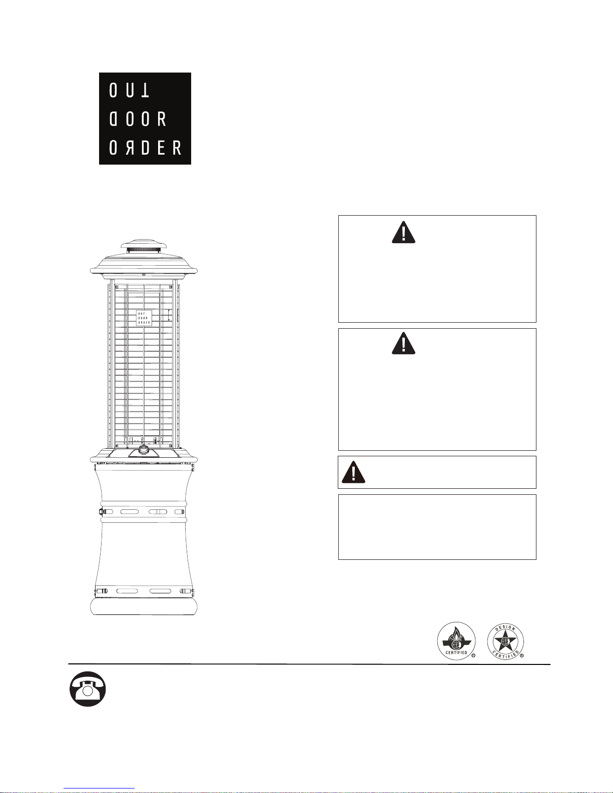
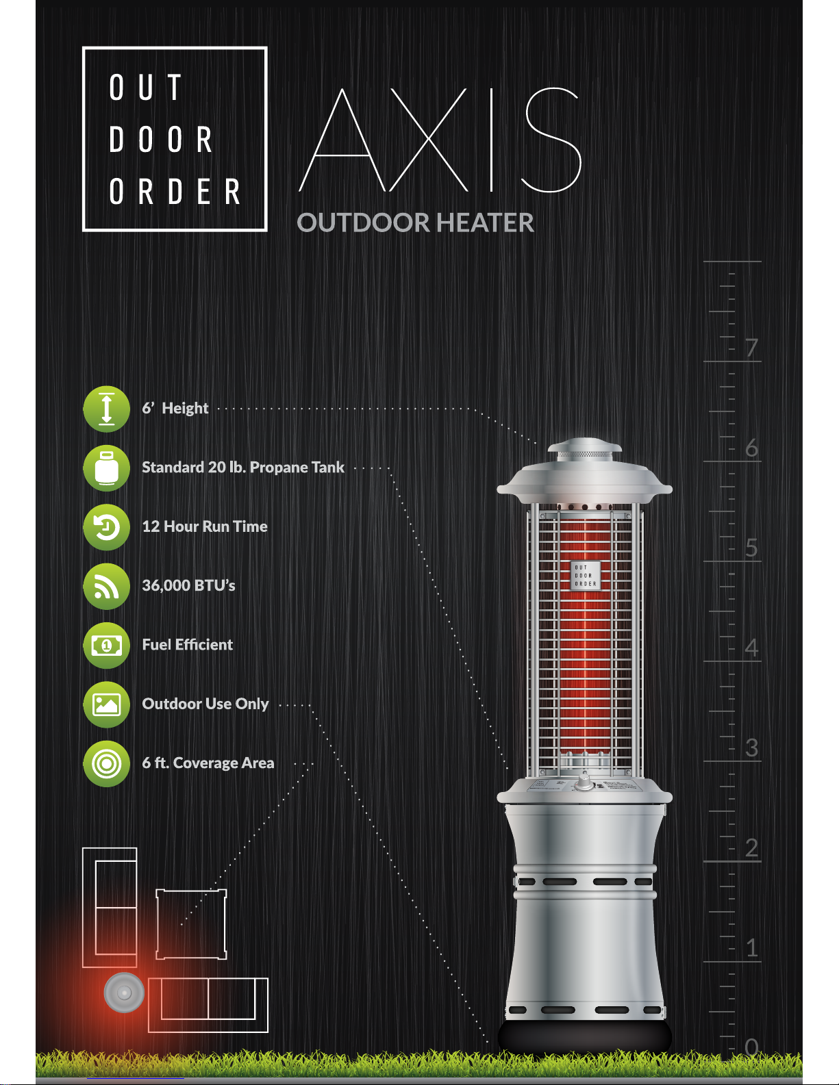
AXIS
OUTDOOR HEATER
Owner’s Manual
Questions, problems, missing / replacement parts? Before returning to your retailer,
call our customer service department at 1-866-814-0585, 8 a.m.-8 p.m., EST,
Monday-Friday.
If you smell gas:
1. Shut off gas to the appliance.
2. Extinguish any open flame.
3.
If odor continues, keep away from
the appliance and immediately call
your gas supplier or fire department.
Do not store or use gasoline or
other flammable vapors and liquids
in the vicinity of this or any other
appliance.
An LP-cylinder not connected for
use shall not be stored in the vicinity
of this or any other appliance.
DANGER
WARNING
CAUTION:
Installer: Leave the manual instructions
to the user for future use.
Consumer: Please keep this manual
for future reference.
Read the instructions before use.
This appliance must be installed in
accordance with such regulations as
are in force.
Model#
MTC-AXIS-GM-LP
WARNING:For Outdoor Use Only.
Page 3
2
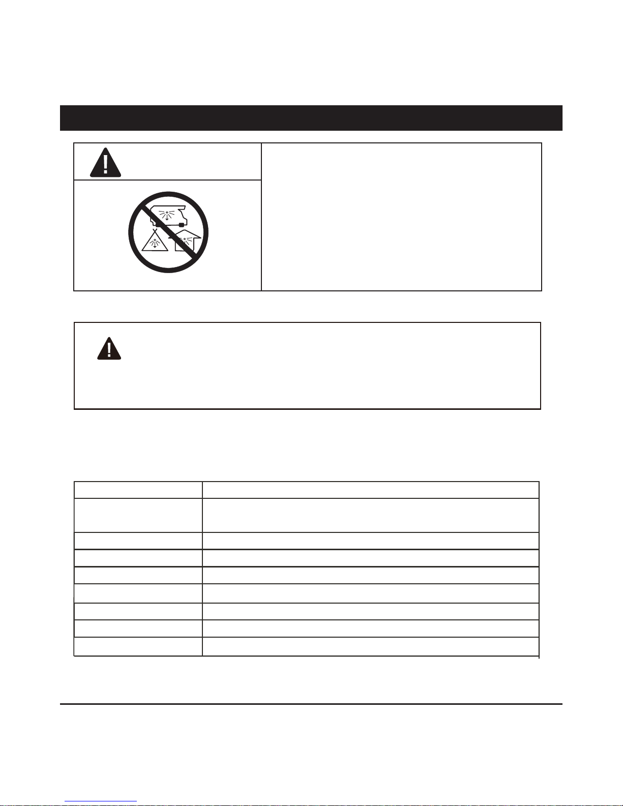
This appliance can produce carbon monoxide
which has no odor.
Using it in an enclosed space can kill you.
Never use this appliance in an enclosed space such
as a camper, tent or home.
DANGER
CARBON MONOXIDE HAZARD
WARNINGS AND CAUTIONS
SPECIFICATION
Certification CSA
Height BALI-I68: 70.87" (1.80 m)
BALI-DI69: 74" (1.88 m)
Rated heat input 36,000 BTU/hr
Fuel LP
Gas Supply 20 lb (9 kg) LP gas cylinder
Manifold pressure 11" W.C.
Diameter of injector 1/13" (1.90 mm)
Safety features Flame failure device, anti-tilt switch
Gas supply pressure Max. 250 PSI, Min. 5 PSI
WARNING: Improper installation, adjustment, alteration, service or
maintenance can cause property damage, injury or death. Read the installation, operating
and maintenance instructions thoroughly before installing or servicing this equipment.
Page 4
3
The installation must conform with local codes
or, in the absence of local codes, with the
National Fuel Gas Code, ANSI Z223.1/NFPA 54,
NFPA58 Natural Gas and Propane Installation
Code, CSA B149.1, or Propane Storage and
Handling Code, B149.2
The heater, when installed, must be electrically
grounded in accordance with local codes or, in
the absence of local codes, with the National
Electrical Code, ANSI/NFPA 70, or the Canadian
Electrical Code, CSA C22.1.
Children and adults should be alerted to
the hazards of high surface temperatures
and should stay away to avoid burns or
clothing ignition.
Young children should be carefully
supervised when they are in the area of
the heater.
Clothing or other flammable materials
should not be hung from the heater, or
placed on or near the heater.
Prior to use, check for damaged parts such as
hoses, regulators, pilot or burner.
All leak tests should be done with a soapy solution. NEVER USE AN OPEN FLAME TO
CHECK FOR LEAKAGE.
The propane hose with regulator assembly shall
be located out of pathways where people may
trip over it or in areas where the hose will not be
subject to accidental damage.
Any guard or other protective device
removed for servicing the heater must be
replaced prior to operating the heater.
Installation and repair should be done by
a qualified service person. The heater
should be inspected before use and at
least annually by a qualified service
person.
More frequent cleaning may be required
as necessary. It is imperative that control
compartment, burners and circulating air
passageways of the heater be kept clean.
Keeping the appliance area clear and free from
combustible materials, gasoline and other flammable vapors and liquids.
Not obstructing the flow of combustion and ventilation air.
Keeping the ventilation opening(s) of the cylinder enclosure free and clear from debris.
This appliance shall be used only in a wellventilated space and shall not be used in a building, garage or any other enclosed area.
An appliance may be installed with shelter no
more inclusive than:
With walls on all sides, but with no overhead
cover.
Within a partial enclosure which includes an
overhead cover and no more than two side
walls. These side walls may be parallel, as in a
breezeway, or at right angles to each other.
NOTE:PLEASE READ THE FOLLOWING SAFETY RULES
WARNING:
WARNINGS AND CAUTIONS
Page 5

4
The pressure regulator and hose assembly supplied with the appliance must be used, replacement pressure regulators and hose assemblies
must be those specified by the appliance manufacturer.
Do not store a spare LP-gas cylinder under or
near this appliance;
Never fill the cylinder beyond 80 percent full;
Do not clean the heater with cleaners that are
combustible or corrosive.
NOTE:PLEASE READ THE FOLLOWING SAFETY RULES
Place the dust cap on the cylinder valve outlet
whenever the cylinder is not in use. Only install
the type of dust cap on the cylinder valve that is
provided with the cylinder valve. Other types of
caps or plugs may result in leakage of propane.
Within a partial enclosure which includes an
overhead cover and three side walls, as long as
30 percent or more of the horizontal periphery of
the enclosure is permanently open.
This appliance requires 9kg(20lb) LP-gas supply
cylinder.
The LP-gas supply cylinder to be used must be:
Constructed and marked in accordance with the
Specifications for LP-gas cylinders of the U.S.
Department of Transportation (DOT); or the
Standard for Cylinders, Spheres and Tubes for
Transportation of Dangerous Goods and Com-
mission, CAN/CSA-B339, as applicable;
Provided with a listed overfilling prevention
device; and provided with a cylinder connection
device compatible with the connection for the
appliance.
The cylinder be disconnected when the appli-
ance is not in use.
Storage of an appliance indoors is permissible
only if the cylinder is disconnected and removed
from the appliance.
A cylinder must be stored outdoors in a well-
ventilated area out of the reach of children. A
disconnected cylinder must have dust caps
tightly installed and must not be stored in a building, garage or any other enclosed area.
WARNING:
WARNINGS AND CAUTIONS
Certain materials or items, when stored under
the heater, will be subjected to radiant heat and
could be seriously damaged.
Inspect the visible portion of the hose before
each use of the appliance and inspect the entire
hose assembly at lease annually.
The cylinder used must include a collar to protect
the cylinder valve.
Page 6

5
This heater is designed to operate with a standard 20 Ib propane cylinder with Approved Cylinder
Connection.
NOTE: PLEASE READ THE FOLLOWING SAFETY RULES:
PREPARATION
Before beginning assembly of product, make sure all parts are present. If any part is missing or
damaged, do not attempt to assemble the product. Contact customer service for replacement parts.
Perform a leak test with a soapy solution:
1. T
o check gas connections.
2. After connecting a new cylinder
.
3. Upon re-assembly after disassembly
.
WARNINGS AND CAUTIONS
Page 7
6
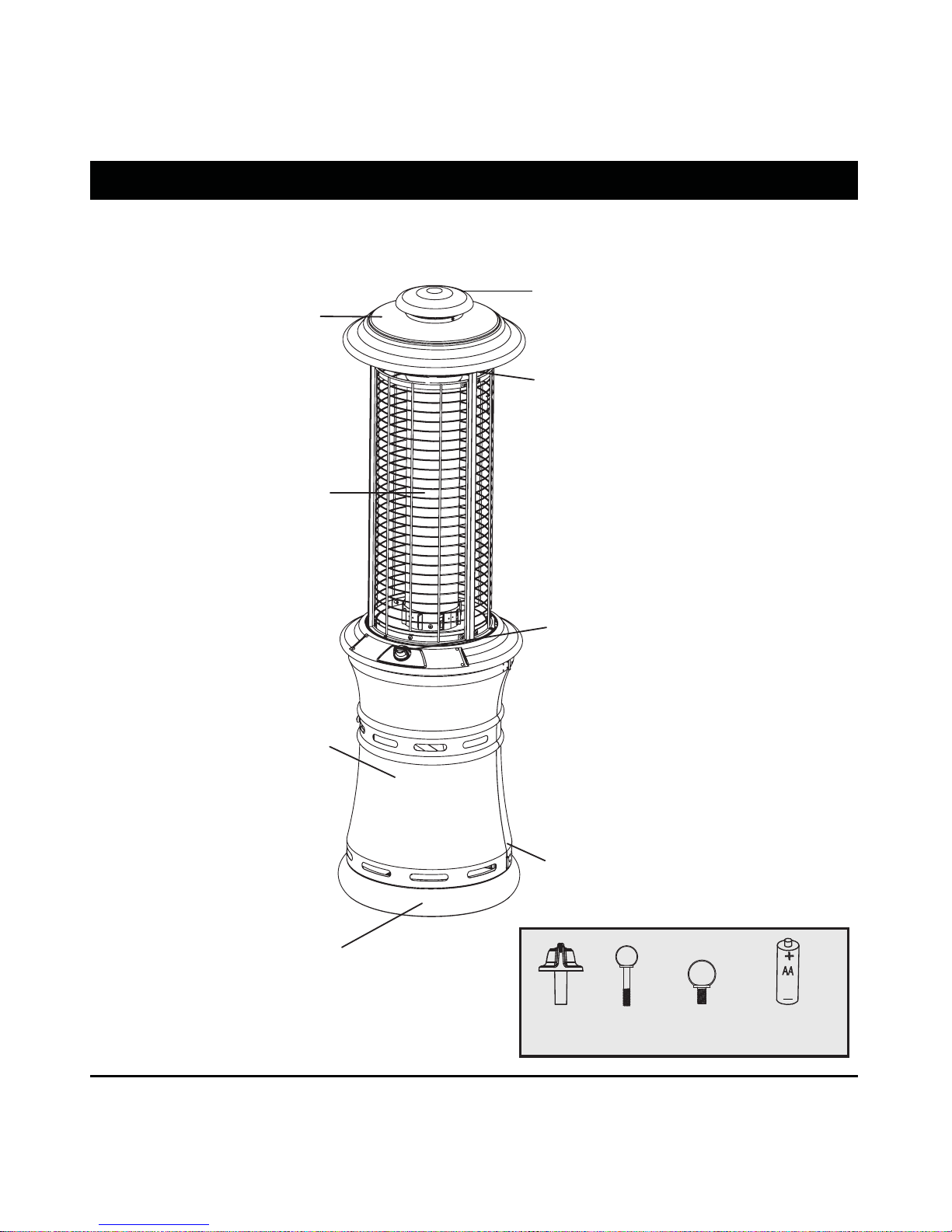
PARTS CONTENTS
Please check the contents of the packaging as to whether anything is missing!
A hinged metal door is provided for
easy access to the LP gas cylinder.
Heat exchange tube has a large
heat-radiating surface.
Safety guard protects the full
height of the heat exchanger tube.
Gas control with electronic igniter is
centrally positioned for easy access.
Integrated wheels allow for easy
transport.
The large base ensures good stability.
Chimney cover
Weather resistant heat reflector
prevents water from entering the
combustion zone and reflects
heat down.
Control
Knob
AA Battery(1.5V)
(not included)
M6x12
Thumb
Screw
M6x35
Thumb
Screw
Page 8

7
ASSEMBLY INSTRUCTIONS
Step 1
Step 2
S
door. Carefully lift heat reflector until entire heat exchange
tube is exposed.
tep1: To assemble unit-partially open gas chamber
Step 2: After heat exchange tube is fully extended, rotate
counter-clockwise until stopped.
Warning:This appliance requires installation
by a competent person. Proper assembly is
the responsibility of the installer.
Page 9

1
2
3
ASSEMBLY INSTRUCTIONS
8
Step 4
Step4: Fully open gas chamber door. Place control
knob on control stem.
Remove the knob from control stem and store it inside the
bracket inside the door when you lower down the heat
exchange tube, and don't use the heater for a long time.
Warning:This appliance requires installation by a
competentperson. Proper assembly is the
responsibility of the installer.
Step3: Insert M6x35 thumb screw into hole A, and M6x12
thumb screw into hole B. Lock the screws.
After raising and pivoting heat exchange tube, tighten two
thumb screws to lock into place. Failure to do so could
allow heat tube to drop during use. Tighten screws before
operation!
CAUTION!
Step 3
A
B
Page 10

9
ASSEMBLY INSTRUCTIONS
Step 5
Step 6
Step5: Place battery in compartment below control panel.
Warning:This appliance requires installation
by a competent person. Proper assembly is
the responsibility of the installer.
Step6: Place the gas cylinder (not included) into the base
assembly , and fix it with fixing chain. Attach the regulator
to the cylinder, turn clockwise to tighten it securely, and
then close the door.
Note: Make sure to check for leaks once the cylinder has
been replaced. (Refer to the “check for leaks” section on
page 10)
Tighten
Page 11

10
SAFETY CHECK
Check for leaks
All connections on the patio heater have been
checked for leakage at the factory. In
transportation and handling some connections
may have loosened. Follow these
steps to check
the gas hose/regulator/cylinder connections:
1) Make leakage solution by mixing 1 part liquid
dish soap and 3 parts water.
2) Spoon or brush several drops (or use squirt
bottle) of the solution onto hose connection,
regulator & cylinder connection.
3)Turn on gas cylinder valve. Inspect the
connections and look for bubbles.
4) If no bubbles appear
, the connection is safe.
5) If bubbles appear, there is leakage. Loosen
and re-tighten this connection. If connection
still leaks, please call customer service:
1-866-814-0585.
Note:
1)
The cylinder supply system must be arranged
for vapor withdrawal;
2)
The cylinder used must include a collar to
protect the cylinder valve.
regulator & cylinder
connection
WARNING : ONLY AN AUTHORIZED GAS TECHNICIAN SHOULD INSTALL THIS PRODUCT.
The hose assembly must be replaced prior to the
appliance being put into operation if there is
evidence of excessive abrasion or wear, or if the
hose is damaged.
At least once a year, a complete inspection of the
entire gas path components should be performed.
If there is need to replace parts, proceed to leak
test after reassembly (These procedures should
be performed by a professional technician).
Page 12

OPERATION
11
WARNING: DO NOT ATTEMPT TO OPERATE HEATER UNTIL YOU HAVE READ AND
UNDERSTAND ALL PRECAUTIONS. FAILURE TO DO SO CAN RESULT IN SERIOUS
PERSONAL INJURY, DEATH, OR PROPERTY DAMAGE.
Before turning gas supply ON
Your heater was designed and approved for OUTDOOR
USE ONLY. DO NOT use it inside a building or any other
enclosed area.
Make sure surrounding areas are free of combustible
materials, gasoline, and other flammable vapors or liquids.
Ensure that there is no obstruction to air ventilation.
Be sure all gas connections are tight and there are no leaks.
Be sure the access panel is clear of debris.
Be sure any component removed during assembly or
servicing is replaced and fastened prior to starting.
Before Lighting
Heater should be thoroughly inspected before each use,
and by a qualified service person at least annually.
If relighting a hot heater, always wait at least 5 minutes.
WARNING
FOR YOUR SAFETY:
If at any time you are unable to
light burner and smell gas, wait 5
minutes to allow gas to dissipate
before attempting to light heater.
If after 1 minute, you are unable
to light burner, wait 5 minutes
and allow flammable vapors to
dissipate before attempting to
light heater.
WARNING
FOR YOUR SAFETY:
DO NOT touch or move heater
for at least 45 minutes after use.
Allow emitter and heat reflector
to cool before touching.
WARNING
Lighting operations should
comply with Lighting Instruction
section. Improper lighting
operations will cause serious
injury and explosion.
Lighting instructions
1) Turn the control knob to “OFF” position.
2) Turn LP cylinder gas valve to fully open position.
3) Turn knob counter-clockwise to “IGNITE”. Hold knob
down to activate “IGNITE” until lit. (It is also possible to
ignite the appliance using a long match, by approaching
the burner through the ignition hole provided.)
If pilot does not light, turn knob clockwise to “OFF”. Wait
5 minutes and repeat the procedure.
Page 13

OPERATION
12
4) When the pilot is lit keep knob pressed for up to 20
seconds to heat the thermocouple flame sensor
,
then
release it (first ignition generally takes more time,
because the gas circuit is full of air).
5) If the pilot does not stay lit, repeat steps 3 and 4.
6) Turn knob to “LOW “ position.
7) Adjust the heat input by turning the knob from the “LOW“
position, to the “HIGH” position, as required.
8)
After lighting, turn knob from “LOW “ to “HIGH”, position
and back, to check flame stability
.
9) In case of accidental break down of the flame (due to
wind or other reasons), a Flame Safely Device (FSD) will
automatically shut-off gas supply within 90 seconds.
If you experience any ignition problem consult the following
“Troubleshooting”.
These lighting instructions must be followed. An unsafe
condition can occur if they are not followed correctl
Flame Characteristic
The flame pattern at the emitter screen should be visually
checked whenever heater is operated.
y.
If black spot is accumulating on the emitter grid or reflector,
the heater should be turned off immediately. The heater
should not be operated again until the unit is serviced and
or repaired.
Thermocouple
Pilot Assembly
Page 14

OPERATION
NOTE:
The burner may be noisy when initially turned on. To eliminate
excessive noise from the burner, turn the Control Knob to the "LOW"
position. Then, turn the knob to the level of heater desired.
When heater is ON:
Emitter grid will become bright red due to intense heat. The color
is more visible at night.
These flames should not or produce thick black smoke, indicating an
obstruction of airflow through the burners.
Operation pressure checked:
If the flame is very small, this is because the supply pressure is not
enough. Please refill gas cylinder.
Re-light:
1) Turn the control knob to "OFF" position.
2) Wait five (5) minutes before attempting to relight pilot.
3) Repeat steps beginning with step 2 of the lighting instruction
above.
Shut down instructions:
1) Push in and turn control knob clockwise to "OFF" position.
2)
Turn LP cylinder gas valve clockwise to "OFF" position when
heater is not in use.
Note: After use, some discoloration of the emitter screen is normal.
The Event of Gas Leakage:
1)
Turn the control knob to "OFF" position.
2) Turn LP cylinder valve to “OFF” position.
3) Wait 5 minutes to allow gas to dissipate.
4) If odor continues, immediately call gas supplier
.
WARNING : Heater will be hot after use.
Handle with extreme care.
CAUTION : AVOID INHALING FUMES EMITTED FROM THE HEATER'S FIRST USE. SMOKE AND
ODOR FROM THE BURNING OF OILS USED IN MANUFACTURING WILL APPEAR. BOTH
SMOKE AND ODOR WILL DISSIPATE AFTER APPROXIMATELY 30 MINUTES. THE HEATER
SHOULD NOT PRODUCE THICK BLACK SMOKE.
13
Page 15

14
LOCATING HEATER FOR USE
CAUTION: WHEN CERTAIN MATERIALS OR ITEMS ARE LEFT, ABOVE, BESIDE OR UNDER
THIS HEATER WHILE IN USE, THEY WILL BE SUBJECT TO RADIANT HEAT AND COULD BE
SERIOUSLY DAMAGED.
This heater is primarily used for the heating of
outdoor patios, decks, spas, pools and open
working areas.
Always make sure that adequate fresh air
ventilation is provided. Follow the spacing
tolerances shown in the following figure right at
all times.
This heater must be placed on level, firm
ground.
Never operate in an explosive atmosphere.
Keep away from areas where gasoline or other
flammable liquids or vapors are stored or used.
Page 16

15
MAINTENANCE/STORAGE
DO NOT touch or move heater for
at least 45 minutes after use. Allow
all burner elements to cool before
touching.
FOR YOUR SAFETY ;
WARNING:
NOTE:
In a salt-air environment (such as
near an ocean). corrosion occurs
more quickly than normal.
Frequently check for corroded
areas and repair them promptly.
NOTE:
wait until heater is cool before
covering.
CLEANING AND MAINTENANCE :
To enjoy years of outstanding performance from your
heater make sure you perform the following maintenance
activities on a regular basis:
Keep exterior surfaces clean.
Use warm soapy water for cleaning. Never use
flammable of corrosive cleaning agents.
While washing your unit, be sure to keep the area
around the burner and pilot assembly dry at all times. If
the gas control is exposed to water in any way, do NOT
try to use it. It must be replaced.
Keep the appliance area free and clean from combustible
materials, gasoline and other flammable vapors and
liquids; not obstructing the flow of combustion and
ventilation air; keeping the ventilation opening(s) of the
cylinder enclosure free and clear from debris.
Gas odor with extreme yellow tipping of flame.
Heater does NOT reach the desired temperature.
Heater glow is excessively uneven.
Heater makes popping noises.
Visually check burner flames.
Check if there are cracks or worn sections on hose. If
yes, please call our customer service to replace hose.
At least once a year, the unit should be inspected for
the presence of spiders, spider webs or other insects.
Air flow must be unobstructed. Keep controls, burner,
and circulating air passageways clean. Signs of possible
blockage include:
Check the cracks or worn sections
Page 17

16
MAINTENANCE/STORAGE
NOTE:
wait until heater is cool before
covering.
Turn the control knob to "OFF" position.
Turn LP cylinder to "OFF" position.
Store heater upright in an area sheltered from direct
contact with inclement weather (such as rain, sleet, hail,
snow, dust and debris).
If desired, cover heater to protect exterior surfaces and
to help prevent build up in air passages.
Spiders and insects can nest in burner or orifices. This
dangerous condition can damage heater and render it
unsafe for use. Clean burner holes by using a heavy-duty
pipe cleaner. Compressed air may help clear away
smaller particles.
Carbon deposits may create a fire hazard. Clean heat
reflector and heat exchange tube with warm soapy
water if any carbon deposits develop.
STORAGE:
Between uses:
During periods of extended inactivity or when
transporting;
Turn LP cylinder to "OFF" position
Unhook fixing chain.
Disconnect the regulator from the LP Cylinder by turning
counter-clockwise and move LP cylinder to a secure,
well-ventilated
Remove 2pcs thumb screws. Remove knob from control
panel and store in door. Keep gas chamber door partially
open. Turn heat exchange tube clockwise. Slowly
descend heat exchange tube.
Always remove the battery from the patio heater if not
being used for long periods of time as battery leakage can
cause corrosion in the battery ignition housing.
location outdoors. DO NOT store in a
location that will exceed 125 degrees F.
Store heater upright in an area sheltered from direct
contact with inclement weather (such as rain, sleet, hail,
snow, dust and debris).
If desired, cover heater to protect exterior surfaces and to
help prevent build up in air passages.
WARNING:
Do NOT keep the heater fully
extended and the heat exchange
tube must be lowered down to
position during transportation!
.
Page 18

TROUBLESHOOTING
17
Gas valve may be OFF
Fuel tank empty
Air in supply system
Loose connection
Debris around pilot
Loose connection
Defective thermocouple
Gas leak in line
Lack of fuel pressure
Pressure is low
Control valve not ON
Thermocouple broken
Pilot light assembly bent or not
in correct location
Fuel tank is near empty
Turn valve to ON
Contact customer service
Contact customer service
Clean dirty area
Tighten connection
Contact customer service
Check connections
Fuel tank is near empty
Turn the gas valve ON
Refill LP gas tank
Purge air from lines
Check all fittings
Pilot will not light
Pilot will not stay on
Burner will not light
PROBLEM PROBABLE CAUSE SOLUTION
Page 19

21
one 1
OUTDOOR ORDER LLC.
1-866-814-0585
cs@outdoororder.com
Page 20

MANUFACTURED BY:
OUTDOOR ORDER LLC.
T. 1.866-814-0585
cs@outdoororder.com
1900 Burgandy Place, Ontario, CA 91761
Dear Valued Customer,
Thank you for your recent purchase from Outdoor Order. We pride ourselves in
providing the most innovative, reliable and stylish outdoor comfort products in
the industry. Our mission is simple, bring order to the outdoors.
Our collection meets the highest manufacturing standards and is backed by an
unmatched industry warranty. Tough enough for the most demanding commer-
cial environment and yet accessible to the discriminating consumer, Outdoor
Order products stand alone in an industry we are proud to be a part of.
As an original equipment manufacturer Outdoor Order has been delivering unri-
valed quality and unprecedented design to our partners for over a decade. No
problem is too small and no order is too big, thats our mantra. Our customer ser-
vice department is here to help you with any problem and our logistics and sup-
port team can deliver when you’re in a pinch. We never forget that you come first,
and always will.
Outdoor Order
“BRINGING ORDER TO THE OUTDOORS"
Page 21

 Loading...