

Page 1
User Manual
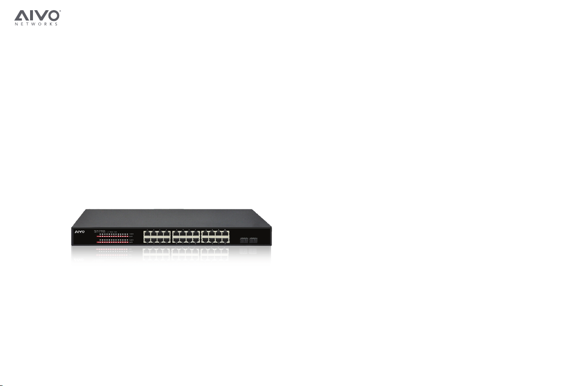
Professional 10/100/1000 Ethernet PoE Switch
AVN-S24-2P24W400G
Introduction
Power over Ethernet (PoE) eliminates the need to run DC power to other devices on
a wired LAN. Using a Power-over-Ethernet system, installers only need to run a single
Category 5 Ethernet cable that carries both power and data to each devices. This reduce
equipment and installation cost significantly and allows much more flexibility in locating
a network devices.
There are two system components in PoE- the PSE (Power Sourcing Equipment) and
the PD (Powered Device). The IEEE 802.3af/at specification defines PSE as a device that
inserts power onto an Ethernet cable. The PSE may be located at the switch (Endspan
configuration) or it may be a seperate device located between the switch and the PD
(Midspan configuration). The PD is the natural termination of this link, receiving the
power, and could be an IP phone, a WLAN access point, or any other IP device that
requires power. The current is transmitted over two of the four twisted pairs of wires in a
Category-5 cable.
Power over Ethernet follows the IEEE 802.3af/at specification and is completely
compatible with existing Ethernet switches and networked devices. Because the Power
Sourcing Equipment (PSE) tests whether a networked device is PoE-capable, power is
never transmitted unless a Powered Device does not draw a minimum current, because
it has been unplugged or physically turned off, the PSE shuts down the power to that
port. Optionally, the standard permits Powered Devices to signal the PSEs exactly how
much power they need.
The PoE switch is a multi-port fast ethernet switch that can be built high-performance
switch network. This is a store-and-forward device that offers low latency for high-speed
network. It also allows the switch to auto-learn and store source addresses in a 8K-entry
MAC address table. The switch is targeted at workgroup, department or backbone
computing environments.
www.aivonet.com
www.aivonet.com
Page 2

Product Specification
Fixed Port
LED Indicators
Input Voltage
Network Standard
Network Media
Total PoE Budget
Operating Temperature
Storage Temperature
Relative Humidity
Thermal Management
Switching Capacity
MAC Address Table
Traffic Control
Dimensions
Package
PoE Port
PoE Standard
Pin Assignment
24 x 10/100/1000Base-TX ports, 2 1000 Mbps SFP ports
PWR, PoE, Link/Act LED
100V ~ 240V AC, 50/60Hz
IEEE 802.3 10Base-T
IEEE 802.3u 100Base-TX
IEEE 802.3x Flow Control
IEEE 802.3az
10BASE-TX: UTP Category 5/5e Cable (≤250m)
100BASE-TX: UTP Category 5/5e Cable (≤150m)
1000BASE-TX: UTP Category 5/5e Cable (≤150m)
Uplink Fiber Port: Single Fiber 20 km / 12 miles,
Double Fiber 20 km / 12 miles
370W
0°C ~ 40°C (32°F ~ 104°F)
-10°C ~ 70°C (14°F ~ 158°F)
20% ~ 85% (Non-condensing)
Built-in Noiseless FAN
52G
8K
IEEE 802.3x full-duplex flow control
440mm x 200mm x 44mm (W x D x H)
Weight
<5Kg (11lb)
AVN-S24-2P24W400G PoE switch
User Manual
Power Cable
Rack Mount Ears x 2
24 10/100/1000Base-TX ports
IEEE802.3af, IEEE802.3at, per port 15.4W, Max. 30W
V+ (RJ45 Pins 1, 2), V- (RJ45 Pins 3, 6)
FCC Statement
This equipment has been tested and found to comply with the limits for a class B device, pursuant
to part 15 of the FCC rules. These limits are designed to provide reasonable protection against
harmful interference in a commercial installation. This equipment generates, uses and can radiate
radio frequency energy and, if not installed and used in accordance with instructions, may cause
harmful interference with radio communications. Operation of this equipment in a reidential area
is likely to cause harmful interference, in which case, the user will be required to correct the
interference at the user’s expense.
• RJ-45 Ports
Use unshielded twisted-pair (UTP) or shield twisted-pair (STP) cable for RJ-45 connections:
100Ω Category 3, 4 or 5 cable for 10 Mbps connections, 100Ω Category 5 cable for 100Mpbs
connections, or 100Ω Category 5e/above cable for 1000Mbps connections. Also be sure that
length of any twisted-pair connection does not exceed 100 meters (328feet). We suggest
using Category 5e cable when connect a power to the device.
• Improper Network Topologies
It is important to make sure that the network topology is valid. Common topology faults
include excessive cable length and too many repeaters (hubs) between the nodes.
In addition to that, you should make sure your network topology contains no data path
loops. Between any two ends nodes, there should be only one active cabling path at any
time. Data path loops will cause broadcast storms which could severely impact your network
performance.
• Diagnosing LED Indicators
To identify the problems, switches can be easily monitored through panel indicators,
which describe common problems the user may encounter and where the user can find
possible solutions. If the LED display detection isn’t correct, please unplug and plug back
into the cable again. If the power indicator does not light when the power cord is plugged
in, you may have a problem with the power outlet or power connections, power losses, or
surges at power outlet. If the problem still cannot be resolved, please contact the local
serive technician for assistance.
www.aivonet.com
Page 3

Hardware Description
• The Front Panel
The front panel consists of LED Indications and 24 auto-sensing ports.
• LED Indicators
Per Device: Power
Per Port: LINK/ACT (Link/Activity)
Per PoE Port: PoE
2 SFP Port: Speed
Figure 2. Front panel view of LED indications
LED Status Color Description
Power
LINK/ACT
PoE
Speed
On
On
Blinks
Off
On
Off
On
Off
Green
Green
-
-
Green
-
Green
-
The switch is supplied with suitable power.
The port is connecting.
The port is receiving or transmitting data.
The port is not linked successfully with the device
PD is connected
No PD is connected or power forwarding fails
Indicates that the port is running at 1000M
No links
• RJ-45 Ports (Auto MDI/MDIX)
Auto-sensing ports of 10/100/1000 N-way for 10Base-T, 100Base-T, 1000Base-T
connections. [In general, MDI means connecting to another Hub or Switch while MDIX
means connecting to a workstation or PC. Therefore, Auto MDI/MDIX means that you can
connect to another Switch or workstation without changing pin-to-pin or crossover
cabling.] All of these ports can supply to PDs.
.
• The Rear Panel
The rear panel view of the PoE switch consists of a AC power connector.
Figure 3. Rear panel view of the switch
• AC Power Connector
Plug the female connector into the switch and male connector into the power outlet.
Supports input voltages 100~240VAC, 50/60HZ.
Package Contents
Package contents include the following:
• PoE Switch
• AC Power Cord
• 2 Rack-mount Pallet and 6 Screws
• 4 Adhensive-backed Rubber Feet
• User’s Manual
*IMPORTANT: If any piece is missing or damaged, please contact your local dealer or reseller for service.
Network Application
The PoE switch is designed as a segment switch that has a large address table and high
performance to deal with interconnecting networking segments.
PC, workstations, and servers can communicate with each other by directly connecting with
the PoE switch. The switch automatically learns nodes addresses, which are subsequently
used to filter and forward all the traffic based on destination address.
The PoE Switch can provide power to PDs that follow the IEEE 802.3af/at standard in the
network. It solves the problem of the position limitation. For a better performance, the
network devices should be installed in an appropriate position. The following figure is an
example of network application for Power over Ethernet Swtich.
www.aivonet.com
www.aivonet.com
Page 4

Troubleshooting
This section is intended to help solve the most common issues with the PoE Switch.
• Incorrect Connection
Every port on the switch can automatically detect either straight or crossover cables when
you connect it to the Ethernet devices. However, depending on the device, others may
demand a specific cable type. Choose appropriate cable to connect between the units.
The RJ-45 connector should use correct UTP or STP cable, 10/100 Mbps port use 2-pairs
of twisted cable. If the RJ-45 connector is not correctly pinned then the link will fail.
• Faulty or Loose Cables
Look for loose or faulty cable connections. If they are appeared to be okay, make sure the
connections are snug. If the problem is not fixed, try a different cable and disconnect the
cable and reconnect it.
• Non-Standard Cables
Non-Standard and miswired cables may cause numerous network collisions and corrupt
other network performance. A cable tester is the recommended tool to verify the
connection in a cable signal.
www.aivonet.com
www.aivonet.com
 Loading...