

Page 1

INSTALLATION INSTRUCTIONS/
OPERATORS MANUAL
This manual provides
Installation & Operating instructions for
TRAY-TRAC
SYSTEM
NOTIFY CARRIER OF DAMAGE AT ONCE.
It is the responsibility of the consignee to inspect the
container upon receipt of same and to determine
the possibility of any damage, including concealed
damage. Avtec suggests that if you are suspicious of
damage to make a notation on the delivery receipt. It will be the responsibility of the consignee to
le a claim with the carrier. We recommend that you
do so at once.
Manufacture Service/Questions 888-994-7636.
Information contained in this document is known to be
and accurate at the time of printing/creation. Unified Brands
recommends referencing our product line websites,
unifiedbrands.net, for the most updated product information and
specifications.
PP MNL0803
current
1055 Mendell Davis Drive
Jackson, MS 39272
888-994-7636, fax 888-864-7636
unifiedbrands.net
Page 2

TABLE OF CONTENTS
INSTALLATION INSTRUCTIONS
I. SERVICE CONNECTIONS . . 1
A. Electrical . . . . . . . . . . . . . . . . . . . . . . . . . . . . . . . . . . . . . 1
1. Mobile Tray-Trac [Casters] 1
2. Stationary Tray-Trac [Legs] 1
B. Water . . . . . . . . . . . . . . . . . . . . . . . . . . . . . . . . . . . . . . . . . . . 1
1. Mobile Tray-Trac [Casters] 1
2. Stationary Tray-Trac [Legs] 1
C. Drains . . . . . . . . . . . . . . . . . . . . . . . . . . . . . . . . . . . . . . . . . . . 1
1. Hot Food Well Drain . . 1
2. Refrigeration Drain . . 1
OPERATING INSTRUCTIONS
I. STANDARD CONTROLS . . . . . . . . . . . . . . . . . . . . . . . . . . . . . . . . . . . 2
A. Modular Distribution Systems .......................................................................................
B. Start/Stop Stat ion . . . . . . . . . . . . . . . . . . . . . . . . . . . . . . . . . . . 2
C. Speed Control . . . . . . . . . . . . . . . . . . . . . . . . . . . . . . . . . . . 2
III. ACCESSORIES AND CONTROLS 2
A. Momentary Foot Stop Switch 2
B. Fluorescent Work Lights . . . . . . . . . . . . . . . . . . . . . . . . . . . . . . 2
C. Hot Food Wells . . . . . . . . . . . . . . . . . . . . . . . . . . . . . . 2
D. Cold Tops and Cold Pans
E. Checker Audio Call System 3
F. Timer Programmer . . . . . . . . . . . . . . . . . . . . . . . . . . . . . . 3
..
2
3
USER-MAINTENANCE INSTRUCTIONS
IV. PERIODIC CLEANING . . . . . . . . . . . . . . . . . . . . . . . . . . . . . . . . . . 4
A. All Work Surfaces 4
B. Tray Carriers . . . . . . . . . . . . . . . . . . . . . . . . . . . . . . . . . . . . 4
C. Hot Food We ls . . . . . . . . . . . . . . . . . . . . . . . . . . . . . . . . . . . . 4
D. Cold Tops and Cold Pans
V. PERIODIC MAINTENANCE 4
A. Gear Reducer . . . . . . . . . . . . . . . . . . . . . . . . . . . . . . . . . . . . 4
B. Motor Brushes . . . . . . . . . . . . . . . . . . . . . . . . . . . . . . . . . . . . 4
C. Tray Carrier Drive Chain
D. Drains . . . . . . . . . . . . . . . . . . . . . . . . . . . . . . . . . . . . 4
E. Torque Limiter Sprocket 4
F. Refrigeration . . . . . . . . . . . . . . . . . . . . . . . . . . . . . . . . . . . . 4
Important Safety Instructions . . . . . . . . . . . . . . . . . . . . . . . . . . . . . . . . . . . . 5
Grounding Instructions . . . . . . . . . . . . . . . . . . . . . . . . . . . . . . . . . . . . 5
Grounding Instructions for Permanently Connected Appliances . . . . . . . . . . . . . . . . . . . . . 6
VI. EMERGENCY PARTS LIST . . 7
Randell Manufactured Drop in Units Parts List ............................................................................... . 7
Mechanical Parts . . . . . . . . . . . . . . . . . . . . . . . . . . . . . . . 8
Hot Food Drop Ins . . . . . . . . . . . . . . . . . . . . . . . . . . . . . . . 8
HOT Food Well Pa
Fluorescent Light Fixture Parts . 9
Electrical Parts . . . . . . . . . . . . . . . . . . . . . . . . . . . . . . . 9
Component Identification . . . . . . . . . . . . . . . . . . . . . . . . . . . . . . . . . . 10
Component Identification Detail . . . . . . . . . . . . . . . . . . . . . . . . . . . . . . . 11
rts
. . . . . . . . . . . . . . . . . . . . . . . . . . . . . . . . . . 8
. . 4
4
VII. SPECIFIC TECHNICAL DATA AND DIAGRAMS
A. Electrical Schematics
1. Carousel Motor Controls . . 12
VIII. ADDITIONAL INFORMATION
A. Warranty
13
Page 3

INSTALLATION INSTRUCTIONS
I. SERVICE CONNECTIONS
A. Electrical
1.Mobile Tray-Trac [Casters]
a.Power from above
A male connection is provided at the top of
the service pylon. This is the power inlet to
the Tray-Trac System. A drop cord with
matching connector body is supplied for
connecting to the ceiling. To complete the
connection, turn main breakers in each
electrical distribution system OFF, insert
connector body into male receptacle fully
and lock into position with locking collar.
Turn breakers ON to energize Tray-Trac.
b.Power from below
A power supply cord is provided from the
back of the Service Terminal Box to a
matching receptacle in the floor box. To
complete the connection, turn main
breakers in each electrical distribution
system OFF, insert plug fully into receptacle
and lock into position with locking collar.
Turn breakers ON to energize Tray-Trac.
2. Stationionary Tray-Trac [Legs]
a.Power from above
Turn main service breakers in power
supply panel box to OFF while making
connection. The electrical contractor is
to bring rigid or flexible conduit down
from the ceiling into the top of the
service enclosure.
provided within the service enclosure to
which the
connects.
b.Power from below
Turn main service breakers in power
supply panel box to OFF while making
connection. Electrical contractor is to
bring rigid or flexible conduit into back or
bottom of Service Terminal Box. A
terminal is provided within the Service
Terminal Box to which the electrical
contractor connects.
B. Water
1.Mobile Tray-Trac [Casters]
The plumbing connection[s] is usually made
with a flexible hose and quick-disconnect
assembly. To connect quick-disconnect,
slide locking collar on female connector
back and insert male connector. The
A terminal is
electrical contractor
locking collar will snap forward when male
connector is fully inserted. Both halves of
the quick-disconnect are equipped with
self-contained shut-off valves stop the flow
of water as soon as it is uncoupled.
However, we recommend installing a
manual shut-off valve immediately before
the quick-disconnect/hose assembly.
a.Service from above
Install the union end of the water
connector [hose] assembly to the supply
piping in the ceiling.
disconnect male coupling into female on
Tray-Trac unit as described previously.
b.Service from below
A water connector
supplied on the Tray-Trac. If an AVTEC
floor box is supplied, connect the supply
piping to
mounted in AVTEC floor box, then insert
male quick-disconnect as described
above. If an AVTEC floor box is not
supplied, connect female quick-disconnect
to supply piping shut-off valve.
2.Stationary Tray-Trac [Legs]
The plumbing connection[s] is usually
terminated with a 1/4 turn shut-off valve,
which may be located in the base of the unit
[connection from below] or in the service
pylon
plumbing contractor then connects directly
to this valve with rigid pipe.
C. Drains
1.Hot Food Well Drain
a.Direct service connection
Drain normally connected with hard piping
to open floor drain or other waste line.
b.Hose Connection [Optional]
Attach rubber or plastic hose [supplied by
owner] to hose adapter [AVTEC optional
feature] and route to open floor drain.
2.Refrigeration Drain
The drain may be connected if desired, in
the same manner as the hot food well
drain or a bucket may be used in lieu of a
drain connection. The bucket should be
placed under the drain shut-off valve,
located behind the end doors.
[connection from above].
[hose] assembly is
female quick-disconnect
Insert quick-
The
1
1
Page 4

OPERATING INSTRUCTIONS
II. STANDARD CONTROLS
A.Modular Electrical Distribution System
The Tray-Trac has an electrical service
terminal box which is connected to the
main incoming electrical service. From
this point, power supply is provided to
each Modular Electrical Distribution
System [MR0E] running the length of each
side of the Tray-Trac. Each MR0E unit is
a linear panel board, with a main service
disconnect breaker, main system cable
bus and link plates containing a point-ofuse circuit breaker and either receptacle,
switch or internal connection. These link
plates can be moved to any location on
the system, or new plates can be added,
as long as the total kilowatt capacity
[ampacity] of each MR0E unit is not
exceeded.
B.Start/Stop Station
The unit is equipped with one or more pairs
of push buttons which are used to start and
stop the carousel motor. Depressing any of
the STOP buttons will stop the carousel
motor. These switches are intended to start
and stop the carousel at the beginning and
end of the serving period or whenever the
tray carriers will not be in use for an
extended period of time.
C.Speed Control
The unit is supplied with a variable speed
control unit located on the unload end
[inside
STOP/START Station, accessible through
the base cabinet door or access panel.
Trays must be timed manually and
adjustment made on the speed control dial.
See separate instructions for more detailed
information. Max speed of
minute.
III.ACCESSORIES AND CONTROLS
The following optional features may or may
not be supplied. Check drawing and
specifications to determine which features
are included in your systems.
A.Momentary Foot Stop Switch
The Tray-Trac is equipped with a two position
terminal within the Modular Distribution
the Tray-Trac] behind the
10 trays per
2
System at tray unload end. The optional
foot-operated momentary stop switch can be
mounted at this location. Depressing the foot
switch will cause the carousel motor to stop
and it will remain stopped as long as the
switch is depressed. When the operator’s
foot is removed, the carousel will begin
rotating again.
B.Fluorescent Work Lights
Fluorescent work lights may be supplied
beneath the carousel and/or under the
overshelf. The overshelf lights incorporate a
diffuser panel that is integral to the fixture to
reduce glare, protect the bulb an equalize
light distribution. The carousel work lights
use a separate prismatic clear plastic sheet
to protect the bulb and aid in light diffusion.
To replace the carousel bulb, slide the
diffuser panel upward in its slot, and allow the
back edge to drop down and out. The work
lights are operated by a switch that is usually
located alongside the carousel start/stop
switch. Power for the work lights is drawn
from one of the Modular Electrical
Distribution Systems. Three foot fixtures
require #F30-T8 Slimline Lamps, 18” fixtures
require #F15-T8 Slimline Lamps.
C.Hot Food Wells
Heavy-duty rectangular food wells can be
provided with or without drains. Wells are
able to accommodate a standard 12” x 20”
#200 pan up to six inches deep and are
suitable for either wet or dry operation. The
warming element is controlled by an infinite
switch control with a positive-OFF position.
Each food warmer has a separate control A
red signal light indicates a power-ON
condition. Add water to warmer BEFORE
preheating.
DRY, PRE-HEATED WARMER MAY
DAMAGE THE UNIT.
preheating, add hot water, place empty pan
in well, then cover well. Preheating varies
from 15-30 minutes.
NOTE: Hot food wells are warranted
directly by the manufacturer; refer to
separate warranty and owner’s
information.
Some hot food wells may be supplied with a
strainer and drain manifold. This manifold is
POURING WATER INTO A
For most efficient
Page 5
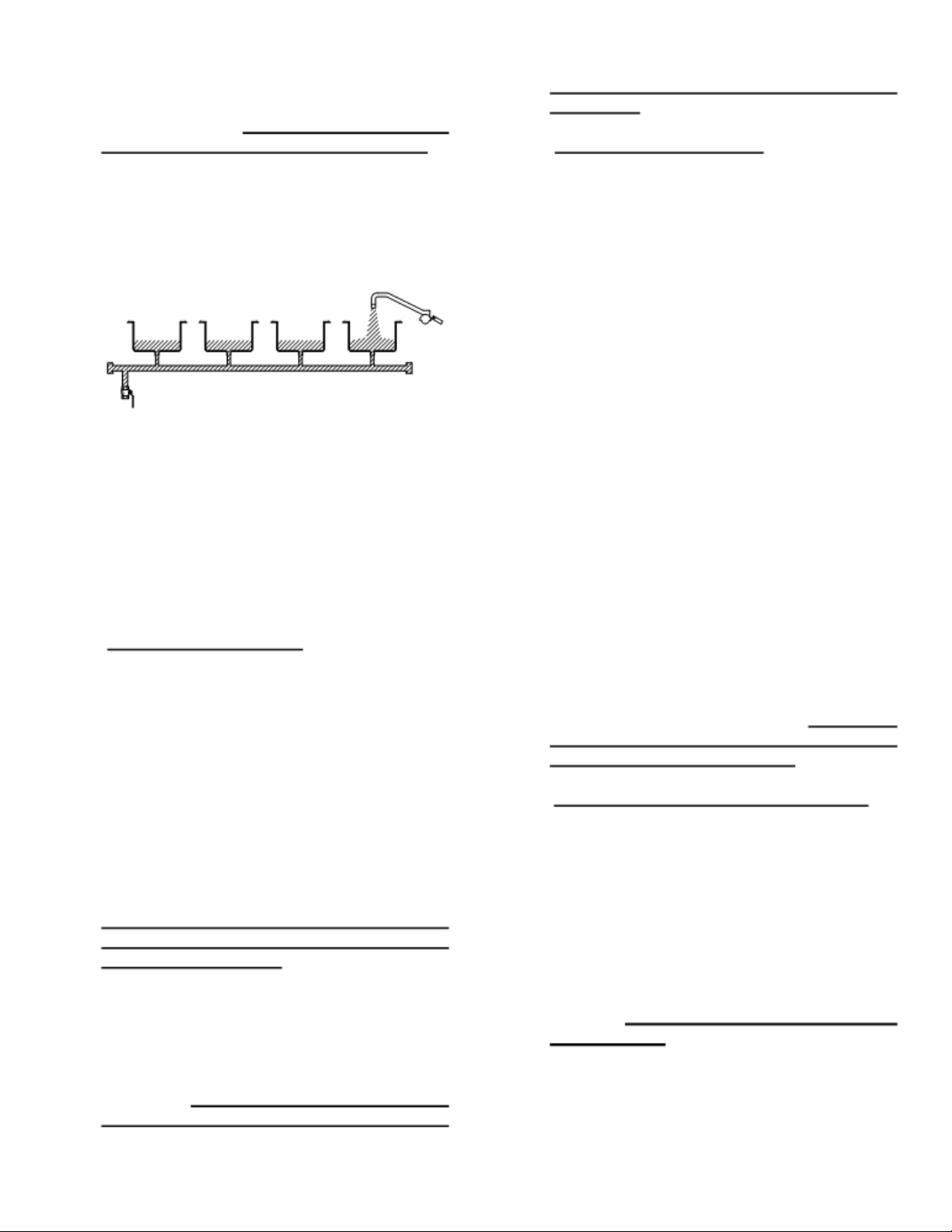
equipped with a ¼ turn ball valve for flushing
and threaded caps at each end for easy
periodic rodding. At least 1” of water should
be in all wells prior to each meal assembly.
The most common method for putting water
into the hot food wells is to back feed through
the drain manifold. By closing the drain
manifold shut-off valve [located in the base
near the end doors] and filling one hot food
well, the water will back up into the other hot
food wells. Hot food wells without drains
must be filled individually and drained with a
cup and sponge.
D.Cold Tops and Cold Pans
Cold Tops [raised cooling surfaces] and Cold
Pans
available for full and half base Tray-Tracs.
The circuits for these items are protected by
breakers in the Modular Distribution Systems.
THESE BREAKERS SHOULD NOT BE
USED TO TURN THE UNITS ON AND OFF.
Switches have been provided beside each
breaker for turning these items on and off.
Units should be turned on approximately
thirty minutes prior to use and left on until the
end of the day.
NOTE: Cold tops and cold pans may or may
not frost, depending on humidity and ambient
atmospheric conditions.
The refrigerated surfaces are supplied with a
removable strainer and drain, which is routed
to one end of the Tray-Trac. This piping is
equipped with a 1/4-turn shut off valve for
flushing and threaded caps for periodic
rodding. To prevent back-up into drain
gutter, the drain should be flushed daily into
[recessed cooling surfaces] are
the open floor drain or bucket, and rodded
periodically.
E.Checker Audio Call System
To aid in communications between the
personnel, a Checker Audio Call Station can
be supplied. Power is supplied from a circuit
breaker connection plate in the Modular
Distribution Panel along the side of the unit.
To turn the system on, make sure that the
circuit breaker is on. Depress the ON/OFF
switch and the Power Indicator LED will
illuminate. If only one microphone is used,
adjust volume by turning the know labeled
“INPUT 1” until the desired level is obtained.
If two microphones are used, adjust the
volume of one microphone using the “INPUT
1” knob and adjust the volume of the second
microphone using the “INPUT 2” knob. The
“PROGRAM” knob is not used in Tray-Trac
applications. When the Checker Audio Call
Station will not be in use for an extended
period of time, turn the unit OFF using power
on/off switch.
After adjusting the amplifier, you are ready to
use the Checker Audio Call Station. To use
the system, hold the button on the side of the
microphone IN while speaking.
microphone is ON only while the button is
held IN.
microphone is mounted on an 18” long
adjustable, flexible gooseneck.
adjustments, consult the amplifier and
microphone operations manual.]
F.Timer Programmer [Seven Day, 24-Hour]
The timer programmer is used to
automatically control the ON/OFF of integral
and ancilliary equipment connected to the
Tray-Trac unit, especially heated bases.
Each Modular Electrical Distribution System
[MR0E] is connected separately thru a
bypass switch to the timer/programmer.
Either MR0E unit may be ON or OFF the
program. The timer/programmer and bypass
switches are located as shown on the
drawing. Refer to separate instructions for
programming.
For your convenience, the
[For further
The
3
Page 6

USER-MAINTENANCE INSTRUCTIONS
IV.PERIODIC CLEANING
A.All Work Surfaces
Entire unit should be wiped down after
every meal and cleaned thoroughly daily
with mild soap and water. *Do not use plain
steel wool, plastic or scouring pads. Use
sponge or towel, if necessary.
*NOTE: Use of these pads will affect the
grain and finish of the metal.
B.Tray Carriers
Tray carriers can be hinged up for daily
cleaning and removed for weekly cleaning.
This also allows the trac to be more
thoroughly cleaned. Do not put tray carriers
in dish machine, as menu holders can be
damaged.
C.Hot Food Wells
Hot food wells should be drained and
cleaned daily. 1/4 turn drain shut off valves
are located near end doors.
D.Cold Tops and Cold Pans
Units should be drained and flushed daily to
prevent clogging and back-up into cold top
gutters or cold pan; 1/4 turn shut-off valve
are located near end doors. All surfaces
should be cleaned at the end of the day.
V.PERIODIC MAINTENANCE
A.Gear Reducer
Change oil after the first month of
operation. Thereafter, change oil after one
[1] year of operation.
Recommended lubricants:
Gulf Transgear #EP680
Mobil 600W Super
Texaco Honor Cylinder Oil #680
B.Motor Brushes
After 2,500
recommended that the motor brushes be
replaced. Refer to the parts list for the
appropriate part number.
hours of operation, it is
4
C.Tray Carrier Drive Chain
Use a spray lubricant on the chain after
one [1] month or 250 hours of operation.
Lubricate after four
hours of operation thereafter.
Recommended lubricant:
McMaster Carr No. 6159K11 Roller Chain
Lubricant
RX Silicone Spray
WD-40
D.Drains
Make sure drain strainers are reinserted
after cleaning. If drains become clogged,
remove threaded end cap, run rod through
drain manifold and replace end cap.
E.Torque Limiter Sprocket
At periodic intervals, or if proper torque is
not being maintained, inspect Torque
Limiter for presence of oil, grease,
moisture, or corrosion on the driving
surfaces and for proper setting of spring
load.
Friction facings and bushings are the only
parts that should normally require
replacement or tightening.
F.Refrigeration
The louvers on the condensing unit
enclosures should be brushed regularly to
prevent clogging of the openings. The
condensing coil of the unit should be
cleaned periodically, for proper function of
the cooling system. Access for service is
obtained by removing the side panel
directly below the cold top or cold pan.
Clean and adjust as required.
[4] months or
500
Page 7

IMPORTANT SAFETY INSTRUCTIONS FOR TRAY TRAC
WARNING - When using electric appliances, basic precautions should always be followed, including
the following:
a)
Read all the instructions before using the appliance.
b) To reduce the risk of injury, close supervision is necessary when an appliance is used near children.
c) Do not contact moving parts.
d) Only use attachments recommended or sold by the manufacturer.
e)
Do not use outdoors.
f)
For a cord-connected appliance, the following shall be included:
- To disconnect, turn all controls the off (“O”) position, then remove from outlet.
- Do not unplug by pulling on cord. To unplug, grasp the plug, not the cord.
- Unplug from the outlet when not in use and before servicing or cleaning.
- Do not operate any appliance with a damaged cord or plug, or after the appliance malfunctions or
is dropped or damaged in any manner. Return appliance to the nearest authorized service facility
for examination, repair, or electrical or mechanical adjustment.
g) For a permanently connected appliance - Turn the power switch to the off position when the appliance
is not in use and before servicing or cleaning.
h)
For an appliance with a replaceable lamp - always unplug before replacing the lamp. Replace only with
the following lamps:
- 36” Fixtures: #F30-T8 Slimline Lamps
- 18” Fixtures: #F15-T8 Slimline Lamps
i)
For a grounded appliance - connect to a properly grounded outlet only. See grounding instructions.
SAVE THESE INSTRUCTIONS
GROUNDING INSTRUCTIONS
This appliance must be grounded. In the event of malfunction or breakdown, grounding provides a path of least
resistance fro electric current to reduce the risk of electric shock. If this appliance is equipped with a cord that
cord contains an equipment-grounding conductor and a grounding plug. The plug must be plugged into an
appropriate outlet that is properly installed and grounded in accordance with all local codes and ordinances.
DANGER - Improper connection of the equipment-grounding conductor can result in a risk of electric shock.
The conductor with insulation having an outer surface that is green with or without yellow stripes is the equipment-grounding conductor. If repair or replacement of the cord or plug is necessary, do not connect the equipment-grounding conductor to a live terminal. Check with a qualified electrician or serviceman if the grounding
instructions are not completely understood, or if in doubt as to whether the appliance is properly grounded. Do
not modify the plug provided with the appliance - if it will not t the outlet have a proper outlet installed by a
qualified electrician.
a) If this is a mobile unit this appliance is rated more than 15A and is for use on a circuit having a nominal
rating of 120V, and is factory equipped with a specific electric cord and plug. No adapter should be
used with this appliance. If the appliance must be reconnected for use on a different type of electric
circuit, the reconnection should be made by qualified service personnel; and after the reconnection,
the appliance should comply with all local codes and ordinances.
b) A qualified electrician should be consulted if there is any doubt as to whether an outlet box is properly
grounded.
5
Page 8
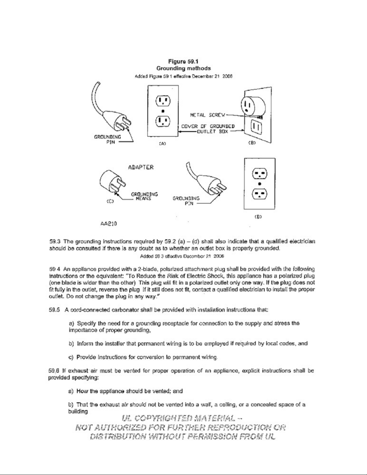
GROUNDING INSTRUCTIONS FOR PERMANENTLY CONNECTED APPLIANCES
This appliance must be connected to a grounded, metal, permanent wiring system; or an equipment-grounding
conductor must be run with the circuit conductors and connected to the equipment-grounding terminal or lead on
the appliance.
GROUNDING METHODS
6
Page 9

VI. TRAY-TRAC EMERGENCY PARTS LIST
AVTEC PART NO. DESCRIPTION
1 HD LCK0301 Panel Lock w/key
2 HD SPR 0302 Menu Ho
3 RP BRK0314 Cha
4 RP CAR0503 Tray Carrier (Right)
5 RP CAR0504 Tray Carrier Assembly [Left]
6 EL FUS0307 Fuse, 10A, SL
7 HD RED0312 Winsmith Reducer
8 EL REC020
9 EL REC5461
10 EL REC0310 Receptacle9330 [208vac, 30A, 1Φ]
11 EL SWT0304 Square Green Start Button w / N.O. contact
12 EL SWT0305 Square Red Stop Button w / N.C. contact
15 HD CNT0305 Wells Hot Food Well Infinite Control
16 EL BRK0301
17 EL BRK0304
18 EL BRK0305
19 EL BRK0308
20 EL BRK 0371
21 EL PTN0301 Potentiometer, 10K ohm
22 EL DIA0301 Dial (Speed Control)
23 EL KNB0301 Knob (Speed Control)
24 EL RES0301 47K OHM Resistor
25 EL RLY0307 Control Relay
26 HD BRD0304 Motor Controller
27 EL CNT0301 Inhibit Pin for 420-0000
28 HD BRS0301 Motor Brushes ¾ HP [up to 26’]
29 HD BRS0303 Motor Brushes 1HP [26’ and over]
30 EL MTR0203 ¾ HP Motor
31 EL MTR0331 1 HP Motor
32 EL ASY0309 Foot Switch Assembly
1 600-2100 Drop in Frost Top 28” x
2 600-2101 Drop in Frost Top 28” x
3 600-2102 Drop in Frost Top 28” x
4 600-2103 1 pan capacity cold drop in 26” x 1
5 600-2104 2 pan capacity cold drop in 26” x 3
6 600-2105 3 pan capacity cold drop in 26” x 4
7 600-2106 4 pan capacity cold drop in 26” x 5
8 600-2107 5 pan capacity cold drop in 26’ x 6
9 600-2108 6 pan capacity cold drop in 26” x 8
10 600-2109 2 pans front to back 2 total cold drop in 25.42” x 31.10”
11 600-2110 2 pans front to back 4 total cold drop in 31.06” x 46.54”
12 600-2111 2 pans front to back 6 total cold drop in 31.06” x 67.36”
13 600-2112 2 pan capacity combo hot or cold drop in 26” x 31.13”
14 600-2113 3 pan capacity combo hot or cold drop in 26” x 43.63”
15 600-2114 4 pan capacity combo hot or cold drop in 26” x 56.50”
16 600-2115 5 pan capacity combo hot or cold drop in 26” x 69.25”
17 600-2116 Drop in Frost Top 28” x 58”
18 600-2117 2 pans front to back 8 total 31.06” x 88.2”
1 HDPCK0301 UHMW Tray Pucks
Receptacle 5362 DCO [120vac, 1Φ, Duplex
Receptacle 5461 [208vac, 20A, 1Φ]
Circuit Breaker 1503 [120vac, 15A, 3Φ]
Circuit Breaker 2003 BQ [120vac, 20A, 1Φ]
Circuit Breaker 2023 BQ [208vac, 20A, 1Φ]
Circuit Breaker 3023 BQ [208vac, 30A, 3Φ]
Circuit Breaker 8024 BQ [208vac, 80A, 3Φ]
RANDELL MANUFACTURED
DROP IN UNITS PARTS LIST
Mechanical Pa
l d
er Sp
r i
ng
i n
Attachment Bracket
- 1
0 , 30 0
r t
s
v
5 8
”
7 6
”
9 4
”
7 .50 ”
0 .40 ”
3 .31 ”
6 .22 ”
9 .13 ”
2 .06 ”
7
Page 10

2 HD TAB0301 Tab for 120-6004
3 HD SPR0302 Menu Card Holding Spring
4 HD LCH0306 Paddle Latches w/Locks
5 HD LCH0304 Paddle Latches
6 HD BMP0301 Bumper Strip [Length x 2 + 11”]
7 120-6001 3
8 120-6002 ¼” x 1
9 PL EXT0301 UHMW 42-118 Profile Wear S
10 PL EXT0302 UHMW 42-114 Profile for chain track edge
11 HD WRM0301 “Wells” Hot Food Wells w/Drain
12 RP DIF0401 Plexiglass Diffuser Panel [specify size]
13 RP CAR0503 Tray Carrier [Right]
14 RP CAR0504 Tray Carrier [Left]
15 HD SPK0303 60 B 32 1” Sprocket
16 HD CHN0301 No. 60 Chain
17 ST SHF0306 1” x 8” Shaft, W 2” Keyway
18 HD BRG0308 RC J-1 Fafner Bearing
19 HD RED0312 Winsmith Reducer
20 HD LMT0301 Torque Limiter
21 HD BSH0301 Torque Limiter Bushing
22 HD SPK0301 Torque Limiter Sprockets
23 PP LBL0359 Blue Logo, “AVTEC”
24 PP LBL0361 Tray-Trac [marker]
25 EL MTR0203 ¾” HP Motor
26 FA BLT0339 Carriage Bolt for 114-0130
/ 8
x 1” UHMW Bar Stock for Chain
[No. trays x 4.7]
- 1
/2” UHMW Bar Stock track bed
[No. trays x 2.35]
[No. trays x 2.35]
[No. trays x 2.35]
t r
ip [for oval ]
RANDELL MANUFACTURED
Hot Food Drop Ins
1 600-2200 Single we l Drop In with drain
2 600-2201 2 well side by side drop in with drains
3 600-2202 3 well side by side drop in with drains
4 600-2203 4 well side by side drop in with drains
5 600-2204 5 well side by side drop in with drains
6 600-2205 6 well side by side drop in with drains
7 600-2300 2 well front to back drop in with drains
8 600-2301 4 well front to back drop in with drains
9 600-2302 6 well front to back drop in with drains
10 600-2303 8 well front to back drop in with drains
Hot Food Well Parts
1 HD SCR0303 Drain Screens
2 EL ELM0301 Heating Element 50398 [SS
3 HD CNT0305 Hot Food We l Control, includes:
a )
Knob
[ 5
0371]
b ) Inf i
nite Switch [54593]
c )
Pi lot Light [50385]
d )
Face Plate [50410]
Fluorescent Light Fixture P
4 RP DIF0401 Fl
5 EL DIF0301
6 EL DIF0302
a t
Light Di fuser Panel 8” x 11”
1 8
” Alko Light Di fuser
3 6
” Alko Light Di fuser
8
- 2
a r
06D]
ts
Page 11

7 EL DIF0303 18” Duray Di fuser
8 150-0046 36” Duray Di fuser
9 EL STR0301 Starter No. FS-4
Ballast Transformer [Rober
10 EL STR101 Starter No. F2-2
Ballast Transformer [Rober
11 EL LGT0309 3’-0’ Fixture Lamp [Tube] 30 watt F30-T8
[Slimline]
12 EL LGT0310 1’-6” Fixture Lamp [tube] 15 watt No. F15-T8
[Slimline]
13 EL ASY0309 Heavy Duty Foot Switch Assembly Parts
[a] EL GRP0301 Straight Cable Grip
[b] EL SWT0327 Foot Switch SPDT N.C.
[c] EL WSH0301 ¾” x ½” Reducer
[d] EL PLG0322 2 Pin Plug w/Cable
7-Day Timer Pa
14 112-0293 Universal Bracket
15 112-0311 Contactor Bracket
16 EL BRK0368 5 amp Circuit Breaker
17 EL RLY0307 Relay, 2PDT, 30 a, 120 vac coil
18 EK TRN0304 Transformer 120:24, 40VA
19 EL VAR0302 Suppressor
20 EL TMR0303 Timer EC-71-24
21 407-1269 Contactor, 3-Pole, 90A, 120vac coil
22 EL SWT0321 Switch DPST, 10a
23 EL CNT0305 4Pin Amp Plug
24 EL CNT0306 4Pin Amp Cap
Electrical Parts
1 EL REC0350 Connector body 100A Risor
2 EL PLG0351 Flanged Receptacle [male] Connection
3 EL PLG0333 Plug 100A] Floor Box
4 EL REC0343 Receptacle
5 EL SWT0304 Square Green Sta
6 EL SWT0305 Square Red Stop Bu ton
7 EL BLK0313 Normally Open Contacts for Sq. Green S
8 EL BLK0403 Normally Closed Contacts for Sq. Red Stop Bu ton
9 EL RES0301 Resistor 47K
10 EL RLY0307 Relay 30A, DPDT, 120vac
11 EL SWT120 Switch, SPST, Bypass
12 EL SWT0321 Switch, 1222 Lights
13 EL STR0301 Starter for 36” Fluorescent Light
14 EL STR101 Starter for 18” Fluorescent Light
15 EL LGT0309 Light 36”
16 EL LGT0310 Light 18”
17 HD MIC0302 Microphone w/Positive Switch
18 EL SPK0401 Speaker 45 ohm
19 EL AMP0401 Bogan Amplifier C-10C
20 412-0308 Connector, Cannon male XLR-3-12
21 EL REC0325 2Pin Receptacle [Foot Switch Recept]
22 HD BRD0304 Motor Controller
r t
s
1 0
0A] Floor Box
r t
Bu ton
t s
on #340BP]
t s
on #SP-2
1 ]
t a
rt Bu ton
9
Page 12

COMPONENT IDENTIFICATION
TRAY-TRAC
ITEM NO. DESCRIP
1 Service Enclosure from Above [Optional]
2 Service From Below [Optional]
3 Main Service Breaker
4 Incoming Service
5 Motor ¾ HP EL MTR0203
6 Start & Stop Station
7 Light Switch EL SWT0321
8 Motor Control Behind Panel HD BRD0304
9 Receptacle for Footswitch EL PLG0322
10 Terminal Plates
11 Refrigeration Compressors
12 Chain HD CHN0301
13 Hot Food Well Controls 51710 HD CNT0305 [Optional]
14 S/S Back Splash or Light [Optional]
15 Bumper-strip HD BMP0301
16 Fafner Bearing HD BRG0308
17 Door Hinges
18 Drain Pipe for Hot Food Wells [Optional]
19 Drain Valve [Optional]
20 Drain-Pipe for Cold Top [Optional]
21 Valve [Optional]
22 Compressor Switch EL SWT0318 [Optional]
23 Over-shelf w/Lights [Optional]
24 Hot Food Wells [Optional]
25 Seal for hot Food Wells [Optional]
26 Cold Top [Optional] or Cold Pan
27 Lights [Optional]
28 Tray Carrier
29 Menu Holder Springs HD SPR0302
30 Caster [2 with locks]
31 Caster or Bullet Feet Height Adjuster [Optional]
32 Fill Faucet
33 Paddle Latches HD LCH0304
34 Paddle Latches w/Lock HD LCH0306
35 Potentiometer EL PTN0303
36 Field Joints
T I
ON
See drawing 4.4A
10
Page 13

11
Page 14

12
Page 15

-WARRANTY-
AVTEC INDUSTRIES INC. warrants to the original purchaser for use of our products, that any part thereof which
proves to be defective in material or workmanship under normal use within one year from date of installation, will be
replaced free of charge. Labor to replace such part is warranted for one year from installation. All warranty labor
to be performed during regular working hours, with no overtime premium.
All Warranty service must be authorized by the factory and be performed by AVTEC’s authorized service
personnel.
This Warranty is limited to the United States and Canada.
This Warranty does not apply to any damage resulting from shipping, improper installation, accident, unauthorized
alteration, local codes not previously brought to the attention of AVTEC, misuse, or abuse; and does not cover
loss of food, other products or damage to equipment or property resulting from mechanical or electrical failure.
AVTEC neither makes nor assumes and does not authorize any other person to assume any other obligation or
liability in connection with its products other than that covered in this Warranty.
.
13
 Loading...