


OPERATORS MANUAL
This manual provides
Installation & Operating instructions for
PAWS VENTILATOR
CONTROLS
For Models:
P30, P31, P32, P33, P34,
P35, P36, P37, P44, P46 and P47
NOTIFY CARRIER OF DAMAGE AT ONCE.
It is the responsibility of the consignee to inspect the container upon receipt of same and to determine the possibility of any damage, including concealed damage. Avtec suggests that if you are suspicious of damage to make a notation on the delivery receipt. It will be the responsibility of the consignee to file a claim with the carrier. We recommend that you do so at once.
Manufacture Service/Questions 888-994-7636.
Information contained in this document is known to be current and accurate at the time of printing/creation. Unified Brands recommends referencing our product line websites, unifiedbrands.net, for the most updated product information and specifications.
1055 Mendell Davis Drive
Jackson, MS 39272 888-994-7636, fax 888-864-7636 avtecind.com
P/N OMANUAL_PVC-09/06
|
|
|
TABLE OF CONTENTS |
|
I. |
GENERAL DESCRIPTION..................................................................................................... |
1-2 |
||
|
A. |
Model Number Guide.................................................................................................. |
1 |
|
|
|
1. |
Models P30, P34 and P44 ............................................................................. |
1 |
|
|
2. |
Models P31, P35 and P45 ............................................................................. |
1 |
|
|
3. |
Models P32, P36 and P46 ............................................................................. |
1 |
|
|
4. |
Models P33, P37 and P47 ............................................................................. |
1-2 |
II. |
INSTALLATION...................................................................................................................... |
2-9 |
||
|
A. |
Wall Attachment.......................................................................................................... |
2 |
|
|
|
1. |
Surface Mounted............................................................................................ |
2 |
|
|
2. |
Recess Mounted ............................................................................................ |
2 |
|
|
3. |
Energy Distribution System Mounted ............................................................ |
2 |
|
B. |
Electrical Interconnection............................................................................................ |
2-7 |
|
|
|
1. |
Control Panel Power Supply.......................................................................... |
2 |
|
|
2. |
Vent Light Switch Power Supply.................................................................... |
2-3 |
|
|
3. |
Fan Starter(s)................................................................................................. |
3 |
|
|
4. |
Vent Exhaust Damper Switch ........................................................................ |
3-4 |
|
|
|
a. Resetable Electro-Mechanical Damper ................................................ |
3 |
|
|
|
b. Fusible Link Damper with Thermo-switch ............................................. |
3-4 |
|
|
|
c. Fusible Link Damper with Damper-switch............................................. |
4 |
|
|
5. |
Water Solenoid(s) .......................................................................................... |
4 |
|
|
6. |
Fire Pull Switch .............................................................................................. |
4-5 |
|
|
7. |
Detergent Pump............................................................................................. |
5 |
|
|
8. |
Detergent Probe............................................................................................. |
5 |
|
|
9. |
Gas Shut Off Solenoid ................................................................................... |
6 |
|
|
10. |
Electric Shunt Trip Output.............................................................................. |
6 |
|
|
11. |
Kill Switch....................................................................................................... |
6 |
|
|
12. |
Hood Fire System Inter-Connection .............................................................. |
6-7 |
|
C. |
Plumbing Interconnection ........................................................................................... |
7-9 |
|
|
|
1. |
Hot Water Supply........................................................................................... |
7 |
|
|
2. |
Hot Water from Panel to Hood Inlets ............................................................. |
7 |
|
|
3. |
Cold Water Mist Supply ................................................................................. |
7 |
|
|
4. |
Cold Water from Panel to Hood Inlet ............................................................. |
7 |
|
|
5. |
Detergent Pump to Pick-up Tube .................................................................. |
8 |
|
|
6. |
Detergent Pump to Injection Tee ................................................................... |
8 |
|
|
7. |
Priming the Detergent Pump.......................................................................... |
9 |
|
|
8. |
Detergent Pump Settings............................................................................... |
9 |
III. |
SEQUENCE OF OPERATION............................................................................................... |
9- |
||
|
A. |
Manual Inputs ............................................................................................................. |
9-10 |
|
|
|
1. |
Fan Off/Wash Off ........................................................................................... |
9-10 |
|
|
2. |
Fan On/Wash Off ........................................................................................... |
10 |
|
|
3. |
Fan Off/Wash On ........................................................................................... |
10 |
|
|
4. |
Fuel Reset...................................................................................................... |
10 |
|
|
5. |
Alarm Silence................................................................................................. |
10 |
|
B. |
Programmed Events ................................................................................................... |
10-11 |
|
|
|
1. |
Fan Off Event................................................................................................. |
10-11 |
|
|
2. |
Fan On Event................................................................................................. |
11 |
|
|
3. |
Wash On Event.............................................................................................. |
11 |
|
C. |
Device Inputs .............................................................................................................. |
11-13 |
|
|
|
1. |
Hood Mounted Exhaust Damper Duct Switch ............................................... |
11 |
|
|
2. |
Hood Fire Suppression system...................................................................... |
11-12 |
|
|
3. |
Fire Pull Switch .............................................................................................. |
12 |
|
|
4. |
AC Power Loss .............................................................................................. |
12 |
|
|
5. |
Detergent Probe............................................................................................. |
12 |
|
|
6. |
PAWS Supervised Water Supply Valve ......................................................... |
13 |
|
|
7. |
PAWS Water Pressure Switch ....................................................................... |
13 |
IV. |
PROGRAMMING INSTRUCTIONS........................................................................................ |
13-15 |
||
|
A. |
Holiday Mode............................................................................................................... |
13 |
|
|
B. |
Wash Duration............................................................................................................. |
13 |
|
|
C. |
Programmed Event Schedule ..................................................................................... |
13 |
|
|
|
1. |
To Program an Event ..................................................................................... |
14 |
|
D. |
Setting the Clock ......................................................................................................... |
15 |
|
|
|
1. |
To Set the Day of the Week ........................................................................... |
15 |
|
|
2. |
To Set AM/PM ................................................................................................ |
15 |
|
|
3. |
To Set the Hour .............................................................................................. |
15 |
|
|
4. |
To Set Minutes ............................................................................................... |
15 |
V. |
ENGINEERING DATA ............................................................................................................ |
16 |
||
|
A. |
Component Layout/Parts List...................................................................................... |
16-18 |
|
|
B. |
Terminal Identification ................................................................................................. |
19 |
|
|
C. Diagnostic Indicators and Switch Settings .................................................................. |
20-22 |
||
|
|
1. |
Model P30 to P37 PLC ................................................................................... |
20 |
|
|
2. |
Model P44 to P47 PLC ................................................................................... |
21-22 |
|
|
3. |
Operator Interface .......................................................................................... |
22 |
VI. |
MAINTAINENCE..................................................................................................................... |
22-23 |
||
|
A. |
Detergent Dispensing System..................................................................................... |
22 |
|
|
B. |
Plumbing...................................................................................................................... |
22-23 |
|
VII |
WARRANTEE |
......................................................................................................................... |
23 |
|
Appendix .............................................................................................................................................. |
|
|
24-45 |
|
|
A. PAWS Programmed Events Worksheet...................................................................... |
25 |
||
|
B. PAWS .....................................................................Sequence of Operation(detailed) |
26-33 |
||
|
C. |
Detergent .................................................................................................Spec Sheet |
34-35 |
|
|
D. Typical ......................................................................................Field Wiring Diagram |
36 |
||
|
E. |
Typical ................................................................................Internal Wiring Diagrams |
37-45 |
|
I.General Description
The AVTEC PAWS panel is supplied as a SubAssembly for an AVTEC Energy Aire Auto Wash Ventilator.
The PAWS panel is provided to control the exhaust and make-up air fans and the Ventilator Auto Wash (cleaning) cycle(s).
One panel will control one or more fans if operated simultaneously. Each panel will operate up to 50 linear feet of ventilator with a single wash output. Sequential wash models include up to 8 wash outputs and can operate up to 400 linear feet of ventilator.
Fan and wash operation may be initiated manually or programmed to occur at a user specified time. The operation of the wash output(s) may be set to a value from 2 to 10 minutes.
The PAWS panel may be provided as a wall mounted unit or integrated into an AVTEC Energy Distribution System (EDS).
Underwriters Laboratories Inc. (UL) list the PAWS panel as:
“SUBASSEMBLY FOR EXHAUST HOOD WITH EXHAUST DAMPER, for USE ONLY WITH AVTEC LABELED HOOD ASSEMBLY FOR EXHAUST HOOD WITH EXHAUST DAMPER”
-And-
“SUBASSEMBLY FOR EXHAUST HOOD WITHOUT DAMPER, for USE ONLY WITH AVTEC LABELED HOOD ASSEMBLY FOR EXHAUST HOOD WITHOUT EXHAUST DAMPER”
All support plumbing and electrical components for the PAWS panel are located within the panel or the EDS. Peripheral plumbing components may be shipped loose for installation in the field by appropriate trades.
A.Model Number Guide
The PAWS control panels are available with a wide variety of options specific to each model number.
To determine the model number of your panel, press and hold the (UP) (DOWN) arrows at the same time. The top display line will read:
Panel Model Number |
|
|
|
|
|
Software |
|
|
|
|
|
Version |
|
|
|
|
|
|||
AVTEC IND. |
P35 |
|
|
|
Number |
|
|
|
|||||
v1.0 |
||||||
PROGRAM WASH QTY. |
2 |
|
||||
1.Models P30, P34 and P44
Features Include:
Manual or Programmed Fan Operation
Adjustable Wash Timer
Manual or Programmed Wash Operation.
Low Detergent Enunciator
Supervised Water Supply Valve Input (connection optional).
Water Pressure Switch Input (connection optional).
Ventilator Exhaust Damper Switch Input (connection optional).
Kill Switch Input (connection optional).
Ventilator Fire System Input (connection optional).
Exhaust Fan Output, 120vac or voltfree normally open contacts.
Supply Fan Output, 120vac or voltfree normally open contacts.
Electric Shunt Trip Output
P30—Single Wash Output
P34—2 to 3 Wash Outputs
P44—4 to 8 Wash Outputs
2.Models P31, P35 and P45
Features Include:
All items listed for model P30.
Fuel Reset with 1-1/2 second delay for latching Gas Solenoid output.
P31—Single Wash Output
P35—2 Wash Outputs
P45—3 to 8 Wash Outputs
3.Models P32, P36 and P46
Features Include:
All items listed for model P30.
Fuel Reset with 120-second delay for latching Gas Solenoid output.
120vac, 600va, Battery Back Up. Provides 120 seconds of operating power for the gas solenoid output and, 4-1/2 hours of power for the operation of the PAWS panel.
P32—Single Wash Output
P36—2 to 3 Wash Outputs
P46—4 to 8 Wash Outputs
4.Models P33, P37 and P47
Features Include:
All items listed for model P30.
120vac, 600va, Battery Back Up. Provides 5 hours of power for the operation of the PAWS panel.
P33—Single Wash Output
P37—2 to 3 Wash Outputs
Wash Output Quantity |
1 |
P47—4 to 8 Wash Outputs
For specific operation of the features listed above refer to the “Sequence of Operation” section of this manual.
II.Installation
Control panel dimensions and connection details are shown on the enclosed shop drawing. Panels may be surface mounted, partially recessed or fully recessed. Typically the bottom edge of the panel is mounted 36” above the floor.
A. Wall Attachment
1.Surface Mounted
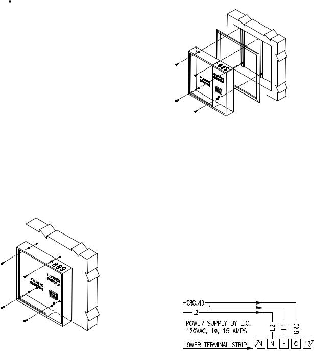
Drill four [4] mounting holes in PAWS panel plumbing compartment. The mounting holes should be near each corner of the box to provide adequate support. Be careful not to damage any components. Do not drill in the electrical compartment since component damage will result. Bolt to wall with anchor bolts or other acceptable means. Weight of control panel varies from 90 lbs. to 200 lbs. See Figure II.A.1
Figure II.A.1
2.Recessed
Cut hole in wall 1/2" greater than overall dimensions of control box [shown on shop drawing]. Spacers or support angles may be necessary to provide proper support. It is recommended that panel be bolted to wall as described for surface mounted above. A stainless steel trim angle is provided and may be set in place with construction adhesive. See Figure. II.A.2
Figure II.A.2
3.Energy Distribution System
The PAWS panel may be provided as an integral part of an AVTEC EDS (Energy Distribution System). All components are pre-mounted.
B.Electrical Interconnection
Project specific wiring schematics are provided in the project installation package.
General Internal Wiring Diagrams (by model) and a Field Interconnection schematic are included in the Appendix of this manual. Individual field interconnections are listed below.
1.Control Panel Power Supply
Provide 120vac, 15amps, single-phase
power. Connect the hot (L1) to terminal “H”, the neutral (L2) to terminal “N”, and the ground to terminal “G”. See Figure II.B.1
Figure II.B.1
2.Vent Light Switch Power Supply
(optional feature)
Provide 120vac, 20 amps, single-phase circuit. Connect the hot (L1) to line side of the switch. Connect the load side of the switch to the black wire in the hood connection box. Connect the neutral and ground wires to the corresponding
2

connections in the hood connection box. See Figure II.B.2
Figure II.B.2
3.Fan Starter(s)
The control voltage for the fan starters may be provided from the PAWS panel (120vac) or the outputs may be configured as volt free normally open contacts.
a)If the fan starters are not pre-wired and require 120vac for the control coils connect as shown in Figure II.B.3.a, “120VAC OUTPUT FROM PAWS PANEL TO FAN STARTERS”.
b)If the fan starter package is prewired and requires connection to normally open volt-free (dry) contacts connect as shown in Figure II.B.3.b “FAN STARTER CONTROL VOLTAGE THROUGH VOLT FREE N.O. CONTACTS”.
Figure II.B.3.a
Figure II.B.3.b
4.Vent Exhaust Damper Switch
(optional feature)
The hoods connected to the panel may include exhaust dampers with switching devices that indicate when the damper has closed due to an extreme temperature rise. There are three types of exhaust damper that may connect to the PAWS panel, Resetable ElectroMechanical, Fusible Link with Thermoswitch, and Fusible Link with damper switch.
a)Resetable Electro-Mechanical Damper
The connection is from the PAWS panel to the hood connection box.
Terminal #7 provides power to the common terminal on the relay. PAWS model series P3** provide 120vac to the common terminal on the relay. PAWS model series P4** provide 24vdc to the common terminal on the relay.
Terminal #8 is connected to the relay normally open contact. The source voltage coming from terminal #7 dictates the switched power through this contact.
Terminal #9 provides 120vac to the Thermo-switch. When the Thermoswitch closes 120vac is passed to the damper solenoid and relay coil.
Terminal “N” is connected to the neutral terminals on the damper solenoid and relay coil. See Figure II.B.4.a.
Figure II.B.4.a
b)Fusible Link Damper with Thermo-switch
The connection is from the PAWS panel to the hood connection box.
3
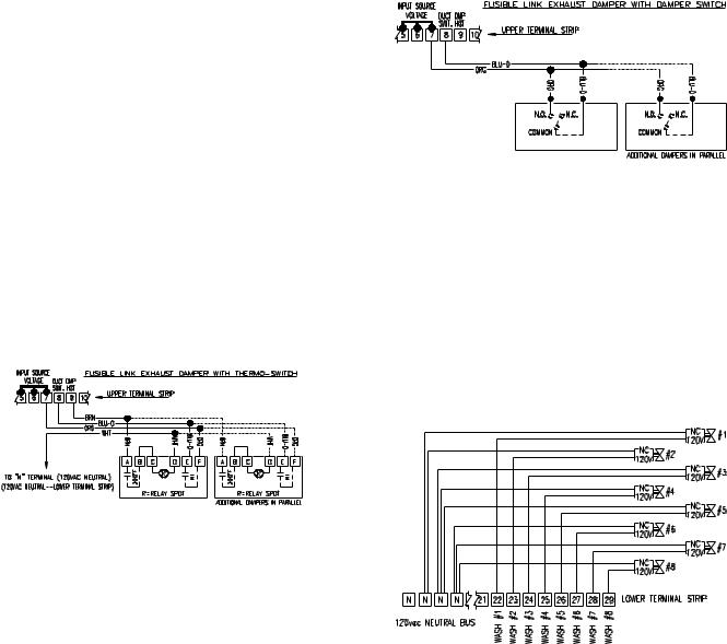
Terminal #7 provides power to the common terminal on the relay. PAWS model series P3** provide 120vac to the common terminal on the relay. PAWS model series P4** provide 24vdc to the common terminal on the relay.
Terminal #8 is connected to the relay normally open contact. The source voltage coming from terminal #7 dictates the switched power through this contact.
Terminal #9 provides 120vac to the Thermo-switch. When the Thermoswitch closes 120vac is passed to the relay coil.
Terminal “N” is connected to the neutral terminal on the relay coil. See Figure II.B.4.b.
Figure II.B.4.c
5.Water Solenoid
The water wash solenoid is installed and pre-wired in panels that have a single wash output.
Water wash solenoids for multiple wash output panels are pre-mounted on the hood. The installing electrician must provide a (2) wire circuit from the panel terminal strip to the each solenoid valve. Terminals #22 through #29 are provided for each wash output (1 to 8). See Figure II.B.5.
Figure II.B.4.b
c)Fusible Link Damper with Damper Switch
The connection is from the PAWS panel to the hood connection box.
Terminal #7 provides power to the normally open contact on the damper switch. PAWS model series P3** provide 120vac to the normally open contact. PAWS model series P4** provide 24vdc to the normally open contact.
Terminal #8 is connected to the common terminal on the damper switch. The source voltage coming from terminal #7 dictates the switched power through this contact. See Figure II.B.4.c
Figure II.B.5
6.Fire Pull Switch (optional feature)
The Fire Pull Switch is an optional feature that allows the user to activate the PAWS Fire Condition manually. The pull switch may be panel mounted and pre-wired, or installed in a remote location (typically at the egress of the kitchen). The normally closed switch is connected to Terminals # 2 and 3. The panel is shipped with a jumper between these terminals. The jumper is removed and discarded once the Fire Pull Switch is connected. Terminal #3 provides power to the common terminal on the
4
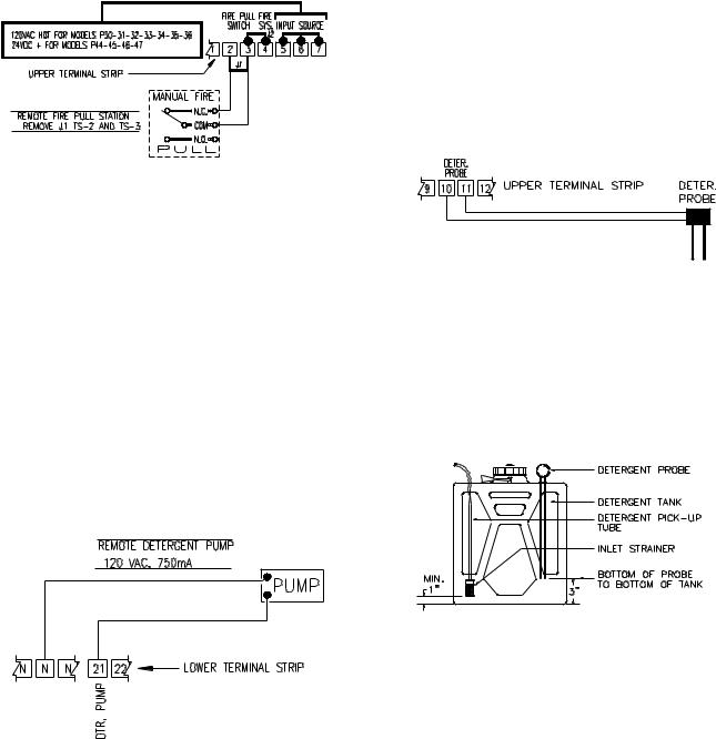
Fire Pull Switch. PAWS model series P3** provide 120vac to the common terminal. PAWS model series P4** provide 24vdc to the common terminal. See Figure II.B.6.
Figure II.B.6
7.Detergent Pump
The Detergent Pump is installed and pre-wired in panels that have an integral Detergent Tank.
Some applications use a remote Detergent dispensing cabinet with a large volume tank (5 gallons) or drum. In these applications the pump is provided in a stainless steel cabinet. The installing electrician must provide a
(3)wire circuit from the panel terminal strip to the Detergent Pump. Terminal #9 is connected to the normally open contact on the pump prime switch, terminal 21 is connected to the normally closed contact on the prime switch. The neutral lead from the pump motor is connected to the “N” terminal strip. See Figure II.B.7.
Figure II.B.7
8.Detergent Probe
The Detergent Probe is installed and pre-wired in panels that have an integral Detergent Tank.
Some applications use a remote Detergent dispensing cabinet with a large volume tank (5 gallons) or drum. In these applications the probe is connected to a terminal strip in the Detergent Pump steel cabinet. The installing electrician must provide a (2) wire circuit from the panel terminal strip to the Detergent Probe. See Figure II.B.8.
Figure II.B.8
The probe should be installed in the detergent container so that it does not protrude below the top of the detergent pump inlet strainer. This is intended to prevent the pump from losing its prime and will advise when the tank needs to be refilled. The probe rods may be cut to facilitate a neat and effective installation. See Figure II.B.8.a.
Figure II.B.8.a
5
 Loading...