


INSTALLATION INSTRUCTIONS/ OPERATORS MANUAL
This manual provides
Installation & Operating instructions for
BUS-TRAC SYSTEM
NOTIFY CARRIER OF DAMAGE AT ONCE.
It is the responsibility of the consignee to inspect the container upon receipt of same and to determine the possibility of any damage, including concealed damage. Avtec suggests that if you are suspicious of damage to make a notation on the delivery receipt. It will be the responsibility of the consignee to file a claim with the carrier. We recommend that you
do so at once.
Manufacture Service/Questions 888-994-7636.
Information contained in this document is known to be current and accurate at the time of printing/creation. Unified Brands recommends referencing our product line websites, unifiedbrands.net, for the most updated product information and specifications.
P/N PP MNL0804 9/08
1055 Mendell Davis Drive
Jackson, MS 39272 888-994-7636, fax 888-864-7636
unifiedbrands.net

TABLE OF CONTENTS
INSTALLATION INSTRUCTIONS |
|
||
I . |
BUS-TRAC INSTALLATION |
1 |
|
II . |
CHAIN ASSEMBLY |
1 |
|
|
A. |
Long Term |
1 |
|
|
Tensioning |
|
|
B. |
Short Term Tensioning |
1 |
|
C. |
Wear Limit |
1-2 |
|
D. |
Offset Link Removal |
2 |
|
E. |
Tray Carrier Attachment |
2 |
I II. |
MOTOR |
2 |
|
|
A. |
Brush Replacement |
2 |
IV. |
BEARING MAINTENANCE |
2 |
|
|
A. |
Schedule |
2 |
|
B. |
Lubr icants |
2 |
V. |
CHAIN MAINTENANCE |
2 |
|
|
A. |
Schedule |
2 |
|
B. |
Lubr icants |
2 |
OPERATING INSTRUCTIONS |
|
||
VI. |
OPERATION |
2 |
|
|
A. |
Start/Stop |
2 |
|
|
Switches |
|
|
B. |
Speed Cont rol |
2 |
|
C. |
Optional Limit Switch |
2 |
VII. |
ELECTRICAL |
2 |
|
|
REQUIREMENTS |
|
|
USER-MAINTENANCE INSTRUCTIONS |
|
||
VI II. |
CLEANING |
2 |
|
|
IMPORTANT SAFETY INSTRUCTIONS |
3 |
|
|
GROUNDING INSTRUCTIONS FOR |
3 |
|
|
PERMANENTLY CONNECTED APPLIANCES |
|
|
IX. |
BUS-TRAC - UPRIGHT AND CARRIER DETAIL |
4 |
|
X. |
BUS-TRAC: MOTOR CONTROLLER WIRING SCHEMATIC |
5 |
|
XI. |
BUS-TRAC PARTS LIST |
6 |
|
XII. |
CALIBRATION PROCEDURE FOR MOTOR CONTROLS |
7 |
|
XI II. |
BUS-TRAC HANGER - RETRO-FIT |
8 |
|
XIV. |
PRESENT BUS-TRAC HANGER |
9 |
|
XV. |
WARRANTY |
10 |
|

INSTALLATION INSTRUCTIONS
I.BUS-TRAC INSTALLATION
A.It is important that the Bus-Trac be mounted level in order to help ensure proper drive component alignment which minimizes drive train wear.
B.If the unit is supported by a wall, shims can
be placed between the Bus-Trac’s frame and the top of the wall. These shims should be either welded in place or held in place by the bolts which secure the Bus-Trac frame to the wall.
C.If the Bus-Trac is supplied with a stainless steel base, be sure that the floor area where the
base is to be located is flat and level. Secure the base to the floor by bolting through the base frame into the floor. Secure the Bus-Trac frame to the base with the bolts supplied.
II.CHAIN ASSEMBLY
A.Normal operation of the Bus-Trac causes chain stretch and wear. The service life of the Bus-Trac chain expires when it has stretched 3%. The original AVTEC chain is installed with offset links which account for 3% of its total length. Stretch is compensated for by removal of the offset links. When all offset links are removed the chain has reached its service limit and must be replaced. Whenever chain replacement is required the associated sprockets should also be replaced.
B.Interim tension can be maintained without removing any offset links. To do this, move the shafts outward as follows: [Refer to fig. 1]
1.Loosen the gearbox mounting bolts [4] and back-off the gearbox tensioning bolts [2].
2.Loosen the shaft bearing mounting nuts [4 per bearing]. [Top and bottom]
3.Loosen the end wear strip mounting nuts [3 per end piece].
4.Loosen the jam nuts on the bearing tensioning bolts.
5.Adjust tension on the driven chain by moving the bearings outward using the bearing tensioning bolts until the chain slack has been removed.
Adjust the tension by moving the driven shafts outward equally at both ends. Use a level to make sure that the shafts are vertical.
IMPORTANT: The upper and lower tensioning bolts must be moved equal amounts.
1
fig. 1
6.When the slack has been removed,
7.Tighten the jam nuts on the bearing tensioning bolts.
8.Tighten the shaft bearing mounting nuts.
9.Tighten the wear strip mounting nuts. 10.Remove the slack from the drive chain by
moving the gearbox/motor assembly using the gearbox tensioning bolts.
11.Tighten the gearbox tensioning bolt jam nuts. 12.Tighten gearbox mounting bolts.
C.When the shaft bearings and/or wear strips
have reached their outward limits, additional tension is achieved by removing offset links from the driven chain. When all of the offset links have been removed and the shaft bearings and/or
wear strips have reached their outer limits, the chain is considered to have reached its service
limit. Any additional wear would require replacement of the driven chain and associated sprockets.
D.Offset links are removed by removing the cotter pins from the roller chain shafts and removing the end plates[s]. Re-assemble the roller chain and insert new cotter pins to hold the end plate[s] in place.
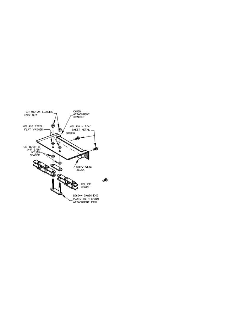
E.If the tray carrier attachment brackets must be replaced, care must be taken when tightening the nuts which hold the brackets in place. Overtorqueing the nuts could pull the shoulders off of the roller chain shafts [Refer to fig. 2].
(FA NUT0330)
(RP BRK0516)
(FA WSH0313) |
(FA SCW3063) |
(PL SPC0302)
(HD BLK0302)
(HD CHN0301)
(HD PIN0301)
fig. 2
III.MOTOR
A. Brush replacement @ 2500 hours or one [1] year.
IV. BEARING MAINTENANCE
A.Lubricate [using Zirk fittings] after one [1] month or 250 hours of operation.
B.Lubricate after every four [4] months or 500 hours of operation thereafter.
Recommended lubricants: Lubrico Type M-6
AVTEC part no. FL LUB0302 Bearing Grease V. CHAIN MAINTENANCE
A.Use a spray lubricant on the drive and
2
driven chains after one [1] month or 250 hours of operation.
B.Lubricate after every four [4] months or 500 hours of operation thereafter.
Recommended lubricants: McMaster Carr No. 6159K11 Roller Chain Lubricant
VI. OPERATION
A.The Bus-Trac is equipped with one or more pairs of push buttons which are used to start and stop the motor. Depressing any of the start buttons will start the tray carriers in motion. Depressing any of the stop buttons will stop the motor. These switches are intended to start and stop the motor at the beginning and end of the busing period or whenever the Bus-Trac will not be used for an extended period of time.
B.The tray carrier speed can be changed [when the Bus-Trac is on] by turning the speed control knob. Turn the knob counter-clockwise to slow the Bus-Trac and clockwise to increase speed. [Maximum speed is approximately sixteen feet per minute (16 fpm).
C.An optional limit switch may be provided
which will turn off the Bus-Trac if something becomes caught on the tray carrier[s] or if something protrudes too far beyond the edge of the tray carrier(s). To resume Bus-Trac operation, clear the obstruction, then press the start button.
VII.ELECTRICAL REQUIREMENTS 120vac, 20 amps, 60 hz
VIII. CLEANING
A.It is important to keep the AVTEC Bus-Trac clean in order to avoid an unsanitary condition. The AVTEC Bus-Trac is designed with easy cleaning in mind. It is recommended that electrical power be turned OFF while cleaning. Removable baskets can be cleaned in all types of dish machines. Sponge the exterior of the unit clean with warm, soapy water and wipe with a clean towel. DO NOT HOSE DOWN the BusTrac, as this may remove lubricants from the chain, causing premature wear. DO NOT USE STEEL WOOL, SOS or BRILLO PADS or other abrasive pads or cleaners on any part of the unit, as it will mar the finish.
B. Individual 2 and/or 3 tier tray carriers may be removed for cleaning and will fit in any 20” x 20” dish rack. Carriers are located on certain tray hanger rungs, according to specific operation.
 Loading...