

Page 1
OPERATORS MANUAL
This manual provides
Installation & Operating instructions for
PAWS VENTILATOR
CONTROLS
For Models:
P30, P31, P32, P33, P34,
P35, P36, P37, P44, P46 and P47
NOTIFY CARRIER OF DAMAGE AT ONCE.
It is the responsibility of the consignee to inspect the
container upon receipt of same and to determine
the possibility of any damage, including concealed
damage. Avtec suggests that if you are suspicious of
damage to make a notation on the delivery receipt.
It will be the responsibility of the consignee to file a
claim with the carrier. We recommend that you do so
at once.
Manufacture Service/Questions 888-994-7636.
Information contained in this document is known to be
and accurate at the time of printing/creation. Unified Brands
recommends referencing our product line websites,
unifiedbrands.net, for the most updated product information and
specifications.
current
1055 Mendell Davis Drive
Jackson, MS 39272
888-994-7636, fax 888-864-7636
P/N PP MNL0805 Revised 10/08
unifiedbrands.net
Page 2
TABLE OF CONTENTS
I. GENERAL DESCRIPTION.......................................................................................................... 1-2
A. Model Number Guide ....................................................................................................... 1
1. Models P30, P34 and P44 ........................................................................... .. 1
2. Models P31, P35 and P45 ........................................................................... .. 1
3. Models P32, P36 and P46 ........................................................................... .. 1
4. Models P33, P37 and P47 ........................................................................... .. 1-2
II. INSTALLATION ... ............................................................................................................................ . 2-9
A. Wall Attachment ... ............................................................................................................... . 2
1. Surface Mounted... ......................................................................................... 2
2. Recess Mounted .......................................................................................... .. 2
3. Energy Distribution System Mounted ............................................................... 2
B. Electrical Interconnection ... ............................................................................................. 2-7
1. Control Panel Power Supply .............................................................................. 2
2. Vent Light Switch Power Supply ........................................................................ 2-3
3. Fan Starter(s) ...................................................................................................... 3
4. Vent Exhaust Damper Switch ... ....................................................................... 3-4
a. Resettable Electro-Mechanical Damper ................................................. 3
b. Fusible Link Damper with Thermo-switch ... .............................................. 3-4
c. Fusible Link Damper with Damper-switch............................................... 4
5. Water Solenoid(s) ............................................................................................ 4
6. Fire Pull Switch ... ........................................................................................... 4-5
7. Detergent Pump ... ................................................................................................ 5
8. Detergent Probe... ............................................................................................ 5
9. Gas Shut Off Solenoid ................................................................................. .. 6
10. Electric Shunt Trip Output .................................................................................... 6
11. Kill Switch ............................................................................................................ 6
12. Hood Fire System Inter-Connection ............................................................... 6-7
C. Plumbing Interconnection ... ............................................................................................ 7-9
1. Hot Water Supply ... ............................................................................................ 7
2. Hot Water from Panel to Hood Inlets ................................................................. 7
3. Cold Water Mist Supply ... ................................................................................ 7
4. Cold Water from Panel to Hood Inlet ................................................................. 7
5. Detergent Pump to Pick-up Tube ..................................................................... 8
6. Detergent Pump to Injection Tee ... .................................................................... 8
7. Priming the Detergent Pump........................................................................... 9
8. Detergent Pump Settings ... ................................................................................ 9
III. SEQUENCE OF OPERATION ... ................................................................................................ 9-
A. Manual Inputs ... .......................................................................................................... 9-10
1. Fan Off/Wash Off ........................................................................................... 9-10
2. Fan On/Wash Off ........................................................................................... 10
3. Fan Off/Wash On ........................................................................................... 10
4. Fuel Reset ............................................................................................................. 10
5. Alarm Silence ................................................................................................. 10
B. Programmed Events ... .................................................................................................. 10-11
1. Fan Off Event ...................................................................................................... 10-11
2. Fan On Event ...................................................................................................... 11
3. Wash On Event ... ............................................................................................... 11
C. Device Inputs ........................................................................................................
1. Hood Mounted Exhaust Damper Duct Switch ................................................ 11
2. Hood Fire Suppression system....................................................................... 11-12
3. Fire Pull Switch ... ........................................................................................... 12
4. AC Power Loss .............................................................................................. 12
5. Detergent Probe... ............................................................................................ 12
.. 11-13
Page 3
6. PAWS Supervised Water Supply Valve ...............................................................13
7. PAWS Water Pressure Switch ... .................................................................... 13
IV. PROGRAMMING INSTRUCTIONS............................................................................................. 13-15
A. Holiday Mode... .............................................................................................................. 13
B. Wash Duration ... ............................................................................................................... 13
C. Programmed Event Schedule ... .................................................................................
1. To Program an Event ... .................................................................................. 14
D. Setting the Clock ... ........................................................................................................
1. To Set the Day of the Week ... .......................................................................... 15
2. To Set AM/PM ..................................................................................................15
3. To Set the Hour .............................................................................................. 15
4. To Set Minutes ... .......................................................................................... .. 15
V. ENGINEERING DATA ...................................................................................................................16
A. Component Layout/Parts List ........................................................................................... 16-18
B. Terminal Identification ... .............................................................................................. 19
C. Diagnostic Indicators and Switch Settings ... .................................................................. 20-22
1. Model P30 to P37 PLC ... .................................................................................... 20
2. Model P44 to P47 PLC ... .................................................................................... 21-22
3. Operator Interface ... ......................................................................................... 22
VI. MAINTAINENCE ..................................................................................................................................22-23
A. Detergent Dispensing System .......................................................................................... 22
B. Plumbing.....................................................................................................................
VII WARRANTEE .................................................................................................................................... 23
Appendix ........................................................................................................................................................... 24-45
A. PAWS Programmed Events Worksheet...................................................................... . 25
B. PAWS Sequence of Operation(detailed)........................................................................ 26-33
C. Detergent Spec Sheet ... .............................................................................................
D. Typical Field Wiring Diagram ... .................................................................................
E. Typical Internal Wiring Diagrams ................................................................................. 37-45
. 13
15
. 22-23
. 34-35
.. 36
Page 4
I. General Description
The AVTEC PAWS panel is supplied as a Sub-
Assembly for an AVTEC Energy Aire Auto Wash
Ventilator.
The PAWS panel is provided to control the
exhaust and make-up air fans and the Ventilator
Auto Wash (cleaning) cycle(s).
One panel will control one or more fans if
operated simultaneously.
operate up to 50 linear feet of ventilator with a
single wash output. Sequential wash models
include up to 8 wash outputs and can operate
up to 400 linear feet of ventilator.
Fan and wash operation may be initiated
manually or programmed to occur at a user
specified time. The operation of the wash
output(s) may be set to a value from 2 to 10
minutes.
The PAWS panel may be provided as a wall
mounted unit or integrated into an AVTEC
Energy Distribution System (EDS).
Underwriters Laboratories Inc. (UL) list the
PAWS panel as:
“SUBASSEMBLY FOR EXHAUST HOOD
WITH EXHAUST DAMPER, for USE ONLY
WITH AVTEC LABELED HOOD
ASSEMBLY FOR EXHAUST HOOD WITH
EXHAUST DAMPER”
“SUBASSEMBLY FOR EXHAUST HOOD
WITHOUT DAMPER, for USE ONLY WITH
AVTEC LABELED HOOD ASSEMBLY
FOR EXHAUST HOOD WITHOUT
EXHAUST DAMPER”
All support plumbing and electrical components
for the PAWS panel are located within the panel
or the EDS. Peripheral plumbing components
may be shipped loose for installation in the field
by appropriate trades.
A. Model Number Guide
The PAWS control panels are available with
a wide variety of options specific to each
model number.
To determine the model number of your
panel, press and hold the (UP) (DOWN)
arrows at the same time. The top display
line will read:
Panel Model Number Version
AVTEC IND. P35 v1.0
PROGRAM WASH QTY. 2
Each panel will
-And-
Software
Number
1. Models P30, P34 and P44
Features Include:
Manual or Programmed Fan
Operation
Adjustable Wash Timer
Manual or Programmed Wash
Operation.
Low Detergent Enunciator
Supervised Water Supply Valve
Input (connection optional).
Water Pressure Switch Input
(connection optional).
Ventilator Exhaust Damper Switch
Input (connection optional).
Kill Switch Input (connection
optional).
Ventilator Fire System Input
(connection optional).
Exhaust Fan Output, 120vac or volt-
free normally open contacts.
Supply Fan Output, 120vac or volt-
free normally open contacts.
Electric Shunt Trip Output
P30—Single Wash Output
P34—2 to 3 Wash Outputs
P44—4 to 8 Wash Outputs
2. Models P31, P35 and P45
Features Include:
All items listed for model P30.
Fuel Reset with 1-1/2 second delay
for latching Gas Solenoid output.
P31—Single Wash Output
P35—2 Wash Outputs
P45—3 to 8 Wash Outputs
3. Models P32, P36 and P46
Features Include:
All items listed for model P30.
Fuel Reset with 120-second delay
for latching Gas Solenoid output.
120vac, 600va, Battery Back Up.
Provides 120 seconds of operating
power for the gas solenoid output
and, 4-1/2 hours of power for the
operation of the PAWS panel.
P32—Single Wash Output
P36—2 to 3 Wash Outputs
P46—4 to 8 Wash Outputs
4. Models P33, P37 and P47
Features Include:
All items listed for model P30.
120vac, 600va, Battery Back Up.
Provides 5 hours of power for the
operation of the PAWS panel.
P33—Single Wash Output
P37—2 to 3 Wash Outputs
Wash Output Quantity
1
Page 5
II. Installation
P47—4 to 8 Wash Outputs
For specific operation of the features listed
above refer to the “Sequence of Operation”
section of this manual.
Control panel dimensions and connection details
are shown on the enclosed shop drawing.
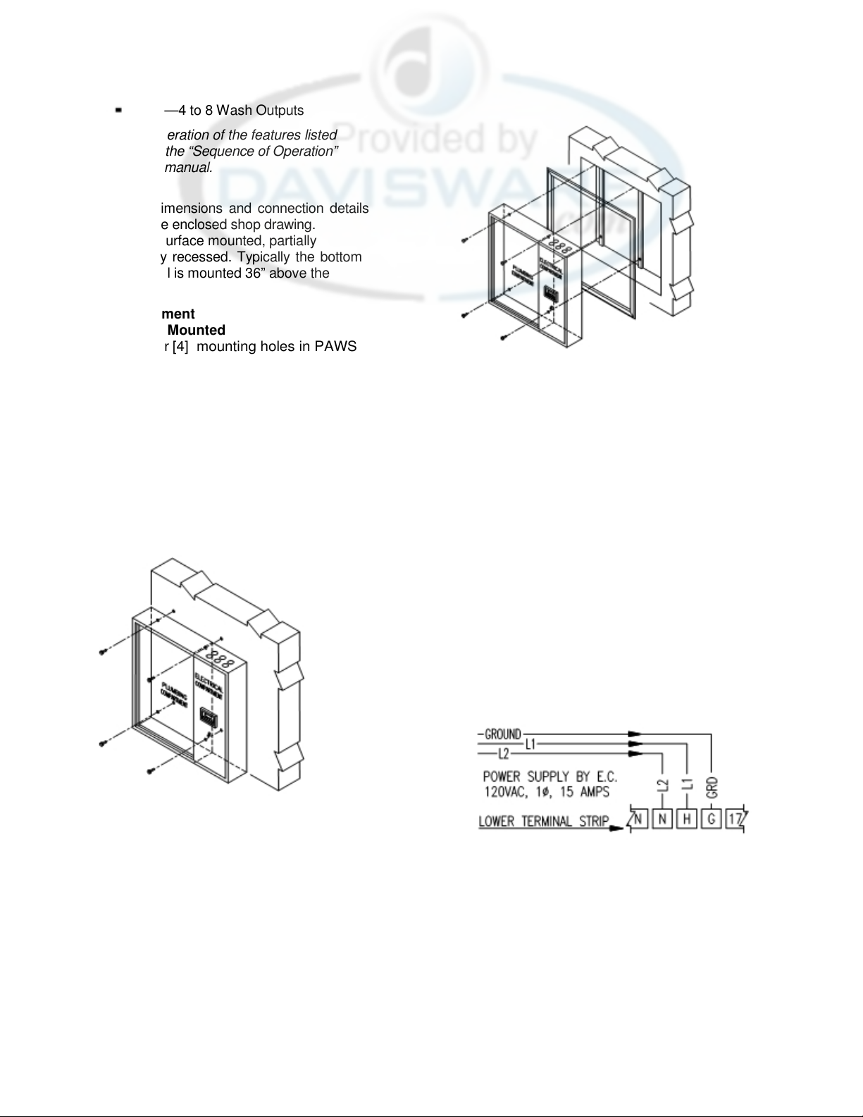
Panels may be surface mounted, partially
recessed or fully recessed. Typically the bottom
edge of the panel is mounted 36” above the
floor.
A. Wall Attachment
1. Surface Mounted
Drill four
panel plumbing compartment.
mounting holes should be near each
corner of the box to provide adequate
support. Be careful not to damage any
components.
electrical compartment since component
damage will result. Bolt to wall with
anchor bolts or other acceptable means.
Weight of control panel varies from 90
lbs. to 200 lbs. See Figure II.A.1
[4] mounting holes in PAWS
The
Do not drill in the
Figure II.A.2
3. Energy Distribution System
The PAWS panel may be provided as
an integral part of an AVTEC EDS
(Energy Distribution System). All
components are pre-mounted.
B. Electrical Interconnection
Project specific wiring schematics are
provided in the project installation package.
General Internal Wiring Diagrams
model) and a Field Interconnection
schematic are included in the Appendix of
this manual.
connections are listed below.
1. Control Panel Power Supply
Provide 120vac, 15amps, single-phase
power. Connect the hot (L1) to terminal
“H”, the neutral (L2) to terminal “N”, and
the ground to terminal “G”.
See Figure II.B.1
Individual field inter-
(by
Figure II.A.1
2. Recessed
Cut hole in wall 1/2" greater than overall
dimensions of control box
shop drawing]. Spacers or support
angles may be necessary to provide
proper support. It is recommended that
panel be bolted to wall as described for
surface mounted above. A stainless
steel trim angle is provided and may be
set in place with construction adhesive.
See Figure. II.A.2
[shown on
Figure II.B.1
2. Vent Light Switch Power Supply
(optional feature)
Provide 120vac, 20 amps, single-phase
circuit. Connect the hot (L1) to line side
of the switch. Connect the load side of
the switch to the black wire in the hood
connection box. Connect the neutral and
ground wires to the corresponding
2
Page 6
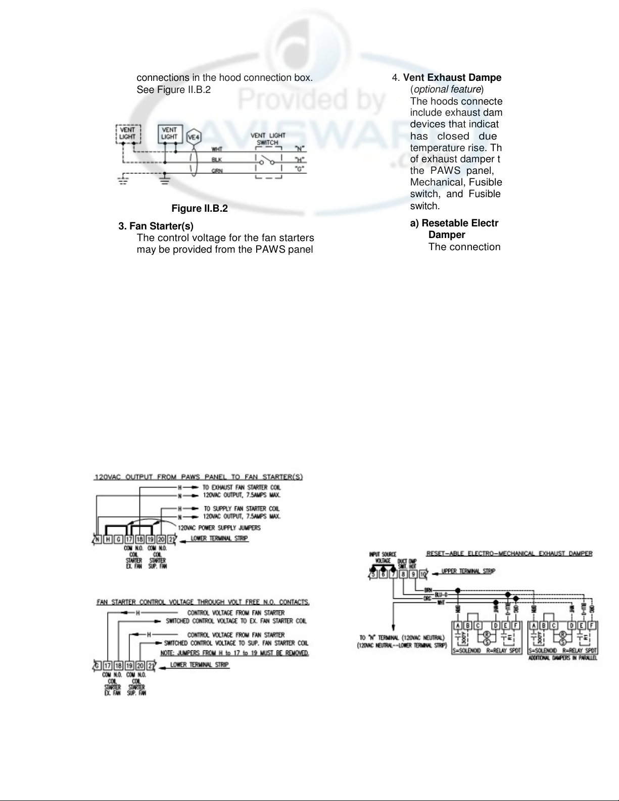
connections in the hood connection box.
See Figure II.B.2
Figure II.B.2
3. Fan Starter(s)
The control voltage for the fan starters
may be provided from the PAWS panel
(120vac) or the outputs may be
configured as volt free normally open
contacts.
a) If the fan starters are not pre-wired
and require 120vac for the control
coils connect as shown in Figure
II.B.3.a,
PAWS PANEL TO FAN
STARTERS”.
b) If the fan starter package is pre-
wired and requires connection to
normally open volt-free
contacts connect as shown in
Figure II.B.3.b “FAN STARTER
CONTROL VOLTAGE THROUGH
VOLT FREE N.O. CONTACTS”.
“120VAC OUTPUT FROM
Figure II.B.3.a
Figure II.B.3.b
(dry)
3
4. Vent Exhaust Damper Switch
(optional feature)
The hoods connected to the panel may
include exhaust dampers with switching
devices that indicate when the damper
has closed due to an extreme
temperature rise. There are three types
of exhaust damper that may connect to
the PAWS panel, Resetable ElectroMechanical, Fusible Link with Thermoswitch, and Fusible Link with damper
switch.
a) Resetable Electro-Mechanical
Damper
The connection is from the PAWS
panel to the hood connection box.
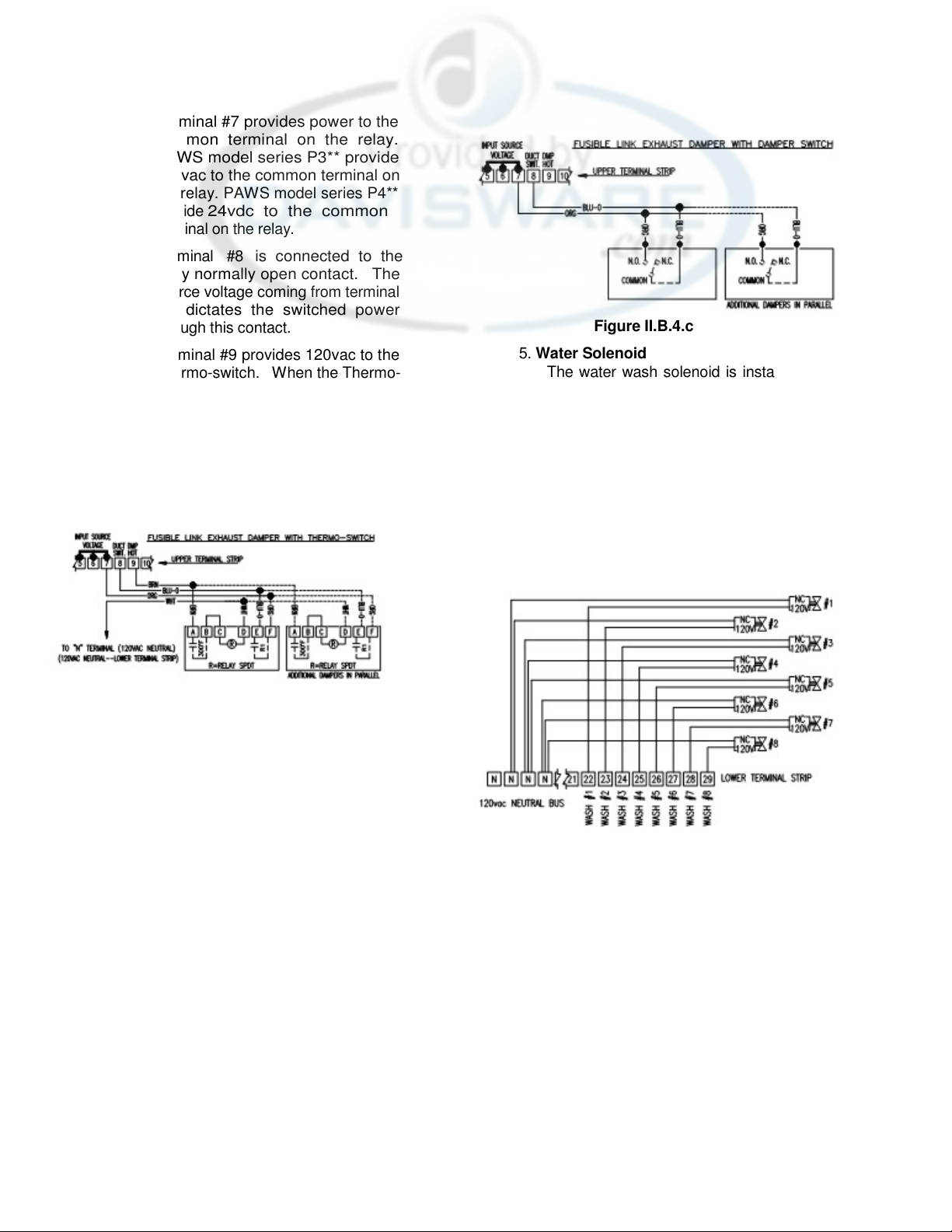
Terminal #7 provides power to the
common terminal on the relay.
PAWS model series P3** provide
120vac to the common terminal on
the relay. PAWS model series P4**
provide
terminal on the relay.
Terminal #8
relay normally open contact. The
source voltage coming from terminal
#7
through this contact.
Terminal #9 provides 120vac to the
Thermo-switch. When the Thermoswitch closes 120vac is passed to
the damper solenoid and relay coil.
Terminal
neutral terminals on the damper
solenoid and relay coil. See Figure
II.B.4.a.
Figure II.B.4.a
b) Fusible Link Damper with
Thermo-switch
The connection is from the PAWS
panel to the hood connection box.
24vdc to the common
is connected to the
dictates the switched power
“N” is connected to the
Page 7
Terminal #7 provides power to the
common terminal on the relay.
PAWS model series P3** provide
120vac to the common terminal on
the relay. PAWS model series P4**
provide
terminal on the relay.
24vdc to the common
Terminal #8
relay normally open contact. The
source voltage coming from terminal
#7
dictates the switched power
through this contact.
Terminal #9 provides 120vac to the
Thermo-switch. When the Thermo-
switch closes 120vac is passed to
the relay coil.
Terminal “N” is connected to the
neutral terminal on the relay coil.
See Figure II.B.4.b.
Figure II.B.4.b
is connected to the
Figure II.B.4.c
5. Water Solenoid
The water wash solenoid is installed and
pre-wired in panels that have a single
wash output.
Water wash solenoids for multiple wash
output panels are pre-mounted on the
hood. The installing electrician must
provide a (2) wire circuit from the panel
terminal strip to the each solenoid valve.
Terminals #22 through #29 are provided
for each wash output
Figure II.B.5.
(1 to
8). See
c) Fusible Link Damper with Damper
Switch
The connection is from the PAWS
panel to the hood connection box.
Terminal #7 provides power to the
normally open contact on the
damper switch. PAWS model series
P3** provide 120vac to the normally
open contact. PAWS model series
P4** provide 24vdc to the normally
open contact.
Terminal #8
common terminal on the damper
switch. The source voltage coming
from terminal
switched power through this
contact. See Figure II.B.4.c
is connected to the
#7
dictates the
4
Figure II.B.5
6. Fire Pull Switch (optional feature)
The Fire Pull Switch is an optional
feature that allows the user to activate
the PAWS Fire Condition manually. The
pull switch may be panel mounted and
pre-wired, or installed in a remote
location (typically at the egress of the
kitchen). The normally closed switch is
connected to Terminals # 2 and 3. The
panel is shipped with a jumper between
these terminals. The jumper is removed
and discarded once the Fire Pull Switch
is connected. Terminal
power to the common terminal on the
#3 provides
Page 8
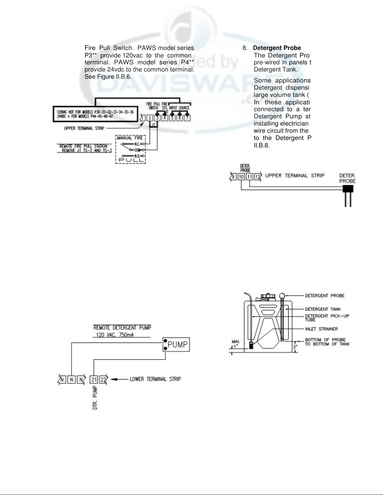
Fire Pull Switch. PAWS model series
P3** provide
terminal. PAWS model series P4**
provide 24vdc to the common terminal.
See Figure II.B.6.
7. Detergent Pump
The Detergent Pump is installed and
pre-wired in panels that have an integral
Detergent Tank.
Some applications use a remote
Detergent dispensing cabinet with a
large volume tank (5 gallons) or drum.
In these applications the pump is
provided in a stainless steel cabinet.
The installing electrician must provide a
(3) wire circuit from the panel terminal
strip to the Detergent Pump. Terminal
#9 is connected to the normally open
contact on the pump prime switch,
terminal 21 is connected to the normally
closed contact on the prime switch. The
neutral lead from the pump motor is
connected to the “N” terminal strip. See
Figure II.B.7.
120vac to the common
Figure II.B.6
Figure II.B.7
8. Detergent Probe
The Detergent Probe is installed and
pre-wired in panels that have an integral
Detergent Tank.
Some applications use a remote
Detergent dispensing cabinet with a
large volume tank (5 gallons) or drum.
In these applications the probe is
connected to a terminal strip in the
Detergent Pump steel cabinet. The
installing electrician must provide a (2)
wire circuit from the panel terminal strip
to the Detergent Probe. See Figure
II.B.8.
Figure II.B.8
The probe should be installed in the
detergent container so that it does not
protrude below the top of the detergent
pump inlet strainer. This is intended to
prevent the pump from losing its prime
and will advise when the tank needs to
be refilled. The probe rods may be cut
to facilitate a neat and effective
installation. See Figure II.B.8.a.
Figure II.B.8.a
5
Page 9

9. Gas Shut Off Solenoid (optional
feature)
An output may be provided to power a
normally closed Gas Solenoid Valve.
The installing electrician must provide a
(2) wire circuit from the panel terminal
strip to the Gas Solenoid. Terminal #14
(120vac hot) and terminal “N” are
connected to the solenoid coil.
Additional valves may be wired in
parallel. See Figure II.B.9.
Figure II.B.9
11. Kill Switch (optional feature)
The Kill Switch is an optional feature
that allows the user to stop the flow of
gas
(for units supplied with a gas
solenoid output) and electricity to the
cooking line served by the panel. Hood
operation
effected. The Kill switch may be panel
mounted and pre-wired, or installed in a
remote location. The Kill Switch is a
momentary, normally open contact set
and is connected to Terminals # 1 and
6. Terminal #6 provides power to the Kill
Switch. PAWS model series P3**
provide 120vac at Terminal #6, PAWS
model series P4** provide 24vdc at
Terminal #6. If more than one Kill Switch
is required additional switches are wired
in parallel. See Figure II.B.11.
(fan and/or wash) is not
10. Electric Shunt Trip Output (optional
connection)
The PAWS panel includes an output
that will energize (120vac) when the
PAWS panel is in a Fire Condition. This
output may be connected to a shunt trip
coil on the main breaker serving the
cooking line.
The installing electrician must provide a
(2) wire circuit from the panel terminal
strip (terminal #15
terminal “N”) to the Electric Shunt Trip
coil. See Figure II.B.10.
Figure II.B.10
(120vac hot) and
Figure II.B.11
12. Hood Fire System Inter-Connection
The Hood Fire Suppression system (for
example, ANSUL R102) must be
electrically connected to the PAWS
panel. When the hood fire system
discharges the PAWS panel will
respond with a Fire Condition (Exhaust
Fan “ON”, Supply Fan “OFF”, Wash
“ON”, Detergent Pump “OFF” Fuel to the
Cooking Equipment “OFF”).
The installing electrician must provide a
(2) wire circuit from the panel terminal
strip (terminal #4 and terminal #5) to a
normally closed (when armed—opens
on discharge) contact set on the hood
Fire Suppression system.
Terminal #5 provides power to the Fire
System Switch. PAWS model series
P3** provide 120vac at Terminal #5,
PAWS model series P4** provide 24vdc
at Terminal #5. See Figure II.B.12.
6
Page 10

Figure II.B.12
C. Plumbing Interconnection
A project specific drawing is provided in the
project installation package that lists specific
connections required, and components that
are supplied by AVTEC.
Individual field interconnections are listed
below.
1. Hot Water Supply
140οF (minimum) hot water, 20-40 psig
is needed to properly clean the extractor
chamber. The Hot Water Supply is
connected to the control panel inlet. A
pressure reducing valve may be
required if water pressure exceeds 60
psig. Refer to your project drawing for
the pipe size required. Typical water
consumption at 30 psig is 1.2 gallons
per minute per linear foot of hood. For
example a
require 12 gallons per minute. Refer to
Figure II.C.1.
2. Hot Water from Panel to Hood Inlets
Hot water piping is required from the
panel outlet to a vacuum breaker-check
valve-detergent injection tee assembly.
NOTE:
Panels with a single wash output
(water solenoid mounted in the
panel) require an atmospheric
vacuum breaker, mounted at least
6” above the hood inlet.
Panels with multiple wash outputs
(water solenoids mounted on hood
sections) require a pressure type
vacuum breaker, mounted at least
18” above the hood inlet.
10’-0” long hood would
Additional piping is required from the
vacuum breaker, check valve, and
detergent injection tee assembly to the
Hood water inlet(s). AVTEC will prepipe multiple hoods to a single inlet
when specified. Refer to your project
drawing for hood inlet connection
requirements. Refer to Figure II.C.1.
3. Cold Water Mist Supply (optional
feature)
When specified, the Cold Water Mist
feature is provided to add an additional
level of grease extraction. The Cold
water mist operates whenever the
Exhaust Fan is running.
The cold water supply (20-30 psig) is
connected to the control panel inlet. A
pressure reducing valve may be
required if water pressure exceeds 30
psig. Refer to your project drawing for
the pipe size required. Typical water
consumption at 30 psig is 0.6 gallons
per minute per linear foot of hood. For
example, a 10’-0” long hood would
require 6 gallons per minute. The Cold
Water Mist manifold is constructed the
same as a single wash Hot Water
manifold. Refer to Figure II.C.1.
4. Cold Water from Panel to Hood Inlet
Cold water piping is required from the
panel outlet to a vacuum breaker-check
valve assembly.
NOTE:
An atmospheric vacuum breaker,
mounted at least 6” above the hood
cold water inlet is required.
The vacuum breaker-check valve
assembly is provided by AVTEC when
specified. Refer to your project drawing.
Additional piping is required from the
vacuum breaker-check valve assembly
to the Hood water inlet(s). AVTEC will
pre-pipe multiple hoods to a single inlet
when specified. Refer to your project
drawing for hood inlet connection
requirements. Refer to Figure II.C.1.
The vacuum breaker-check valve
assembly is provided by AVTEC
when specified. Refer to your
project drawing.
7
Page 11

5. Detergent Pump Pick-up Tube
The pump pick-up tube is provided and
installed by AVTEC when the Detergent
Tank is provided. Some applications use
a remote Detergent dispensing cabinet
with a large volume tank (5 gallons) or
drum. In these applications the pump is
provided with a 5’-0” length of clear PVC
suction tube and a pick-up strainer
screen. The Pick-up tube may not
exceed 5 feet in length. Install as shown
in Figure II.C.1.
6. Detergent Pump to Injection Tee
The output side of the pump (pressure
side) is provided with a pre-piped check
valve. Provide 3/8” O.D. tubing (copper,
or stainless steel) from the detergent
check valve outlet to the injection tee
located between the vacuum breakercheck valve assembly and the ventilator
Figure II.C.1
inlet. Normally the detergent pump and
tank are located in the control panel,
and tubing from the detergent pump to
the detergent tank is factory connected.
Refer to Figure II.C.1.
8
Page 12

7. Priming the Detergent Pump
In order for the pump to function the
pump head must be primed (i.e. all air is
displaced by detergent from the inlet
tube through the pump head). Provided
the Detergent Probe is installed properly
this operation is only required at initial
start-up.
a) Close the PAWS water supply
valve.
b) Ensure that the detergent tank is full
and the pump pick-up tube is
installed as shown in Figure II.C.1.
c) Press the “Fan Off/Wash On”
button.
d) Watch the pre-piped section of clear
output tubing on the pump. Once a
solid column of fluid is present press
the “Fan Off/Wash Off” button. The
pump is primed.
e) Open the PAWS water supply valve.
The Panel is ready for normal
operation.
Figure III
8. Detergent Pump Settings
The pump includes a volume
adjustment. Refer to Figure II.C.1 for the
9
proper setting based on the maximum
hood length washed. To adjust the
pump output:
a) Turn off power to the PAWS panel
by opening DIN rail mounted
fused disconnect.
b) Remove the pump mechanism
cover. It is attached with (1) screw
on the right side. Refer to Figure
II.C.1.
c) Loosen the Adjustment Lock nut
(wing nut).
d) Turn the Graduated Adjustment
Disc so the desired number is in
alignment with the Setting Pointer.
e) While holding the Graduated
Adjustment Disc tighten the
Adjustment Lock nut (wing nut).
f)
Replace the pump mechanism
cover and attachment screw.
g) Restore power to the PAWS panel
by closing the DIN rail mounted
fused disconnect.
III.
Sequence of Operation
A. Manual Inputs
Manual Inputs refer to the operator interface
on the front of the control panel. The five
lower buttons are used for manual operation
of the fans, and to initiate the wash cycle(s).
The five upper buttons are used to program
the PAWS control panel for automatic
operation. See Figure III and III.A.
1. Fan Off/Wash Off button
This button Cancels either fan or wash
operation. A Fire Condition initiated by
the hood Fire System, optional Fire Pull
Switch, or the exhaust damper switch
will override this input. This button will
Figure III.A
Page 13

also cancel the Fire Delay Cycle that
occurs after a Fire Condition has
cleared.
2. Fan On/Wash Off button
This button turns the fans
cancels the wash operation. A Fire
Condition will override this input.
3. Fan Off/Wash On button
This button cancels the fan operation
and initiates the hood wash cycle. The
PAWS panel will wash the hood for an
adjustable period of time (2-10 minutes)
and automatically shut off. This button
is typically used at the end of the day to
shut off the fans and clean the hood.
PAWS models P30* through P33* have
a single wash output. This single output
will control up to a 1-1/2” solenoid valve
that will provide sufficient water flow for
up to 50 linear feet of hood.
PAWS models P34* through P47* have
multiple wash sequences that range
from 2 to 8 outputs, depending on the
model. When a wash cycle is initiated
the outputs operate sequentially, one
after the next. The total time required to
complete all wash sequences is equal to
the length of the wash (adjustable 2-10
minutes) times the number of wash
outputs. For example if you have a 4output PAWS panel and have adjusted
the wash duration for
Wash cycle will operate for 16 minutes
(4 minutes for each output).
4. Fuel Reset button (optional feature)
This button will restore power to the gas
solenoids that control the flow of gas to
the cooking equipment, served by the
hood that is controlled by the panel.
The electrical power to the cooking
equipment may also be restored after
pressing the fuel reset button. A main
service breaker that is equipped with a
shut off device
controls the electrical power.
The fuel-reset feature is provided to
integrate the PAWS panel with the Hood
Fire Suppression system to shut off fuel
to the cooking equipment during a
kitchen fire. There are two types of fuel
reset, one with battery back-up and one
without.
(shunt trip) typically
“ON”, and
4 minutes, the
In the event of a power outage the fuel
reset will:
Units without battery back-up; the
solenoid latching circuit will hold for
1-½ seconds, eliminating the need
to reset the solenoids.
Units with battery back-up; the Gas
Solenoids will remain on for
seconds.
5. Alarm Silence button
This button will silence the horn that
sounds intermittently when the PAWS
panel is in a TROUBLE mode.
A TROUBLE mode may be initiated by a
LOW DETEGENT condition, PAWS
Water Supply Valve Closed (optional),
or, PAWS Water Pressure Low
condition (optional).
If additional trouble conditions occur
after the horn silence button is used; the
horn will not re-sound until all trouble
conditions are cleared and another
trouble condition is initiated.
B. Programmed Events
The PAWS panel can automatically control
the Fan and Wash operation by a user
defined operation schedule. This feature
may or may not be used. It is not required
for the panel to function. There are three
programmable functions:
FAN ON {FAN ON #1 & #2}
FAN OFF {FAN OFF #1 & #2}
WASH ON {WASH ON #1 & #2}
Each of the three functions may be set to
occur twice on a given day (example FAN
ON #1 and FAN ON #2).
Whether a function is initiated manually or
by a programmed event, the last event to
occur takes precedence, with exception to
Fire Conditions. Fire Conditions always
take precedence
1. Fan Off Event
{Fan Off #1 & #2}
This event cancels fan operation. The
Fan Off function is programmed when
the user wishes to cancel fan operation
without initiating a wash, typically used
for daytime fan shut down.
A Fire Condition initiated by the hood
Fire System, optional Fire Pull Switch,
120
10
Page 14

or the exhaust damper switch will
override this input.
Power to the Electric Shunt trip Output
is turned “ON”.
2. Fan On Event
{Fan On #1 & #2}
This event turns the fans “ON”. A Fire
Condition will override this input.
3. Wash On Event
{Wash On #1 & #2}
This event cancels the fan operation
and initiates the hood wash cycle.
The Wash On function is programmed
when the user wishes to cancel fan
operation and initiate the hood wash
cycle. It is best to wash the hood
immediately after the cooking equipment
is shut down, the grease in the hood is
still warm and more easily cleaned. If
the hood is washed after cool down, an
extended wash period may be required.
Typically the user will program this
event as the last function of the work
day, since the fans are shut down and
one wash cycle per day is usually
adequate.
The user may elect to program this
function to occur in the middle of the
night when hot water demand is low.
The fan does not have to be on in order
to program this event.
Please refer to the Programming section
of this manual to ensure the Wash event
does not conflict with other programmed
events.
C. Device Inputs
There are peripheral devices that are
connected to the PAWS panel for purposes
of monitoring operation and causing
variances in panel operation due to external
events. The following is a list of devices and
their effect on panel operation.
1. Hood Mounted Exhaust Damper Duct
Switch (optional hood feature)
Closure of the duct switch indicates that
the exhaust damper on the connected
hood has closed.
Both exhaust and supply fans are turned
“OFF”. The wash spray in the exhaust
plenum is turned
interior of the hood and prevent flame
spread.
“ON” to cool the
In order to return the panel to Normal
operation the Duct Switch must be
open.
When the Duct Switch opens a Fire
Delay Cycle will maintain the plenum
wash spray and fan off condition for a
period of
Delay may be cancelled by pushing the
Fan Off/ Wash Off button.
A Duct Fire Condition takes precedence
over all other events.
A pulsed tone will emanate from the
Alarm Horn while the fire condition is
active.
Following Actions apply to MODELS
P31*, P32*, P35*, P36*, P45* and P46*
ONLY.
Power to the Gas Solenoid output is
turned “Off “
After the Duct Fire Condition and Fire
Delay Cycle are cleared: press the Fuel
Reset button to reset the Gas Solenoid
and Electric Shunt trip outputs.
After the fire condition is cleared the
horn sounds a constant tone until the
Fuel Reset Button is activated.
2. Hood Fire Suppression System
Switch (N.C.) (optional connection)
Normally Closed dry contacts on the
Hood Fire Suppression System (Ansul
R-102, for example) are connected to
the PAWS panel. Upon discharge of the
Fire Suppression system:
The exhaust fan is turned “ON” and the
supply fan is turned “OFF”. The wash
spray in the exhaust plenum is turned
“ON” to cool the interior of the hood and
prevent flame spread.
Power to the Electric Shunt trip Output
is turned “ON”.
In order to return the panel to Normal
operation the Fire Suppression System
must be reset.
When the Fire Suppression System is
reset a Fire Delay Cycle will maintain
the plenum wash spray and fan
condition for a period of 5 minutes. The
5 minutes. The Fire Cycle
11
Page 15

Fire Cycle Delay may be cancelled by
pushing the Fan Off/ Wash Off button.
A Fire System Condition takes
precedence over all events other than a
Duct Switch Event.
Following Actions apply to MODELS
P31*, P32*, P35*, P36*, P45* and P46*
ONLY
Power to the Gas Solenoid output is
turned “Off “.
A pulsed tone will sound from the Alarm
Horn while the fire condition is active.
The following actions apply to
MODELS P31*, P32*, P35*, P36*, P45*
and P46* ONLY
Power to the Gas Solenoid output is
turned “Off “.
After the Fire System Condition and Fire
Delay Cycle are cleared, pressing the
Fuel Reset button will reset the Gas
Solenoid and Electric Shunt trip outputs.
After the fire condition is cleared a
constant tone is delivered until the Fuel
Reset Button is activated.
3. Fire Pull Switch (N.C.) (Panel option)
The optional Fire Pull switch may be
mounted on the PAWS panel or in a
remote location, such as at the point of
egress. When the Fire Pull Switch is
activated:
The exhaust fan is turned “ON” and the
supply fan is turned “OFF”. The wash
spray in the exhaust plenum is turned
“ON” to cool the interior of the hood and
prevent flame spread.
Power to the Electric Shunt trip Output
is turned “ON”.
In order to return the panel to Normal
operation the Fire Pull Switch must be
reset.
When the Fire Pull Switch is reset a Fire
Delay Cycle will maintain the plenum
wash spray and fan condition for a
period of 5 minutes. The Fire Cycle
Delay may be cancelled by pushing the
Fan Off/ Wash Off button.
A Fire Pull Switch Condition is equal to
a Fire System Condition and takes
precedence over all events other than a
Duct Switch Event.
A pulsed tone will emanate from the
Alarm Horn while the fire condition is
active.
After the Fire Pull Switch condition and
Fire Delay Cycle are cleared, the Gas
Solenoid and Electric Shunt trip outputs
can be reset by pushing the Fuel reset
button.
After the fire condition is cleared a
constant tone is delivered until the Fuel
Reset Button is activated.
4. AC Power Loss (N.C.) (Panel option)
Loss of AC power will disable the
outputs of the panel with exception of
the Gas Solenoid circuit (when
provided).
The Fire Pull Switch, Fire System
Switch, Duct Switch, or Kill Switch will
override the AC power loss condition
and cause the actions listed for each
input.
Models P32*, P36*, and P46 ONLY!
After a 2-minute delay, power to the Gas
Solenoid output is turned “OFF”. When
AC Power is restored the “Fuel Reset”
button must be pushed to close the
circuit to the gas solenoid valve output
and open the circuit to the shunt trip
output.
5. Detergent Probe (N.C.)
The detergent probe is provided with the
PAWS panel detergent tank. When the
detergent in the tank is low, the probe
initiates a Low Detergent Condition
(PAWS Trouble Condition).
The Detergent Pump Output is turned
“OFF”.
The Probe is set to disable the pump
prior to losing fluid in the pump body.
The pump will not need to be primed
once the detergent supply is
replenished.
The horn will sound intermittently and
may be silenced with the Alarm Silence
button.
12
Page 16

6. PAWS Supervised Water Supply
Valve (N.O.) (Panel option)
The PAWS panel water supply valve
may be equipped with a switch to
monitor the status of the valve. If the
valve is closed a PAWS Trouble
Condition is initiated. The horn will
sound intermittently and may be
silenced with the Alarm Silence button.
7. PAWS Water Supply Pressure Switch
(N.O.) (Panel option)
The PAWS panel may be equipped with
a pressure switch to monitor adequate
water supply. If the pressure switch is
activated due to low water pressure a
PAWS Trouble Condition is initiated.
The horn will sound intermittently and
may be silenced with the Alarm Silence
button.
IV. Programming Instructions
A. HOLIDAY MODE (Intermittent use)
The
HOLIDAY MODE
suspend programmed Fan/Wash operation.
Set this feature “ON” when normal operation
is suspended during a holiday or shut down
period. Manual operation of the panel is still
active when in Holiday Mode.
When the panel is in “HOLIDAY MODE” the
bottom display line message will alternate
between Fan/Wash status and “
MODE ON”.
To Set HOLIDAY MODE
1. Press the MENU key. Display
Reads: ”SET CLOCK”.
2. Use the (DOWN) arrow key until
the display reads “SET HOLIDAY”.
3. Press the ENTER key. Display
Reads: “SET HOLIDAY MODE”
4. Press the ENTER key. The bottom
display line reads: “SET MODE
X ENTER”.
5. Use the (UP) (DOWN) arrow
keys to adjust the HOLIDAY MODE
ON--OFF
[0=OFF, 1=ON].
6. Press the ENTER key to accept the
adjusted value. Display Reads:
“SET HOLIDAY MODE”.
7. To EXIT press the CLEAR/ABORT
key. To return to the MENU tree
press the MENU key.
is provided to
HOLIDAY
13
B. Set the WASH DURATION
The WASH DURATION is the length of time
each vent wash cycle will run. When a
sequential wash
output) panel is provided each wash will
operate for the set wash duration. The
minimum operational setting is 2 minutes.
The maximum setting is 10 minutes. Typical
setting is 4 to 5 minutes. Under heavy loads
a value of 7 to 10 minutes may be required.
To set the WASH DURATION
1. Press the MENU key. Display
Reads: ”SET CLOCK”.
2. Use the (UP) arrow key until the
display reads “SET WASH
DURATION”.
3. Press the ENTER key. Display
Reads: “SET WASH TIME”
4. Press the ENTER key. The bottom
display line reads: “SET WASH
XX MINUTES”.
5. Use the (UP) (DOWN) arrow
keys to adjust the Wash Time value.
6. Press the ENTER key to accept the
adjusted value. Display Reads:
“SET WASH TIME”.
7. To EXIT press the CLEAR/ABORT
key. To return to the MENU tree
press the MENU key.
C. Set the Programmed Events Schedule
(Automatic Fan On-Off and Wash Cycle)
The PAWS panel can automatically control
the Fan and Wash operation by a user
defined operation schedule.
This feature may or may not be used. It is
not required for the panel to function. There
are three programmable functions:
1. FAN ON {FAN ON #1 & FAN
2. FAN OFF {FAN OFF #1 & FAN
3. WASH ON {WASH ON #1 &
Each of the three functions may be set to
occur twice on a given day (example FAN
ON #1 and FAN ON #2).
Please refer to the PAWS Programmed
Events Worksheet included in the Appendix
of this manual for an outline of the Event
Schedule.
Plan the Programmed Event Schedule.
(more than one wash
ON #2}
OFF #2}
WASH ON #2}
Page 17

Determine your operation schedule by
completing a copy
PAWS Programmed Event Schedule
Worksheet
installation package).
When planning the event schedule you must
account for the time required by the wash
cycle.
In the previous section
Duration” the length of the wash cycle was
determined. Do not schedule fan operation
until sufficient time has passed for the wash
cycle to run to completion.
If your panel includes sequential wash
operation determine the wash output
quantity.
(
DOWN)
bottom display line will read “PROGRAM
WASH QTY. X
the “X” is shown, is the wash quantity value.
Multiply the quantity of wash outputs by the
wash duration to determine the total wash
time required.
EXAMPLE: If
DURATION
output quantity is 4, total wash time is 16
minutes (4 min. wash duration x 4 wash
outputs = 16 minutes).
To stop the operation of the fans a “
OFF” event OR a “WASH ON” event may be
scheduled. While both functions turn the
fans off, the WASH ON function will also run
the hood(s) through a wash cycle.
You may schedule any function independent
of relative functions. For example, if you
normally operate the fans manually, but
want to ensure that the fans are shut off
each night, you could program a “FAN OFF”
event at the end of the day.
operations cook past midnight, so you may
want to program a “
start of the cooking operation, and schedule
a “
FAN OFF”
following day.
1. To Program an Event
a) Press the
b) Use the (UP)
c) Press the
(copy included in the project
Press and hold the
arrows at the same time. The
for 4 minutes, and the wash
Reads: ”SET CLOCK”.
display reads “SET PROGRAM”.
Reads: “SELECT DAY”
(or facsimile) of the
“Setting Wash
”. The value placed where
or “
WASH ON”
MENU
ENTER
you set the
FAN ON
key. Display
arrow key until the
key. Display
WASH
FAN
Some
” event at the
event for the
(UP)
14
d) Press the ENTER key. The bottom
display line reads: “SET DAY
X ENTER”.
e)
Use the
keys to adjust the Day value to the
day you wish to program
[1=Sunday, 2=Monday, 3=Tuesday,
4=Wednesday, 5=Thursday,
6=Friday, 7=Saturday].
f) Press the ENTER key to accept the
adjusted value. Display Reads:
“SELECT DAY”.
g)
Use the (
display reads “SELECT PROGRAM
EVENT”.
h)
Press the
Reads: “FAN ON #1”.
i)
Use the
keys until the display shows the
function you wish to program. In the
following example the “FAN ON #1”
function is used to demonstrate the
programming process.
j)
Press the
Reads:
“FAN ON #1 HOUR X”
k)
Use the
keys to adjust the hour value. If you
wish to clear this programmed
event, adjust the hour value to “0”.
l) Press the ENTER key to accept the
adjusted value. If you accepted a
value other than “0”. Display reads:
“FAN ON #1 MIN. XX”
m)
Use the
keys to adjust the minute value. n)
Press the ENTER key to accept the
adjusted value. Display Reads:
“FAN ON #1 AM/PM. X”
o)
Use the
keys to adjust the AM/PM value
[1=AM, 2=PM].
p) Press the ENTER key to accept the
adjusted value. Display Reads:
“FAN ON #1”.
q) To continue programming
additional events for the same
day:
Use the
arrow keys until the display shows
the function you wish to program.
Repeat steps j to q. Each function
may be scheduled to occur twice
(UP) (DOWN)
UP)
arrow key until the
ENTER
ENTER
key. Display
(UP) (DOWN)
key. Display
(UP) (DOWN)
(UP) (DOWN)
(UP) (DOWN)
(UP) (DOWN)
arrow
arrow
arrow
arrow
arrow
Page 18

per day (Fan On #1-Fan on #2, et
cetera).
r)
To select a new day to program:
Press the
Reads “SELECT PROGRAM
EVENT
arrow key. Display Reads “SELECT
DAY”. Repeat steps c to i.
s)
To back up one level in the menu
tree press the MENU key.
t)
To EXIT and return to the default
Display Messages press
CLEAR/ABORT
only programmed values that will be
saved are those that were
confirmed with an ENTER key.
D. Setting the Clock
The clock does not continue to keep time
when the MENU mode is active. Therefore
the time of day is the last item that should
be set.
1. To Set Day of Week
(a) Press the MENU key. Display
Reads: ”SET CLOCK”.
(b) Press the ENTER key. Display
Reads: “SET MINUTES”
(c) Use the (UP) arrow key until the
display reads “SET DAY OF
WEEK”.
(d) Press the ENTER key. The bottom
display line reads: “SET DAY
X ENTER”.
(e) Use the (UP) (DOWN) arrow
keys to adjust the Day value to the
current day [1=Sunday, 2=Monday,
3=Tuesday, 4=Wednesday,
5=Thursday, 6=Friday, 7=Saturday].
(f) Press the ENTER key. The bottom
display line reads: “SET DAY OF
WEEK”.
MENU
”. Press the
key. Display
at any time. The
(DOWN)
3. To Set Hour
(a) Use the (UP) arrow key until the
display reads “SET HOUR”.
(b) Press the ENTER key. Display
Reads: “SET HOUR X
Enter”.
(c) Use the (UP) (DOWN) arrow
keys to adjust the Hour value to the
current time.
(d) Press the ENTER key to accept the
adjusted value. Display Reads:
“SET HOUR
4. To Set Minutes
(a) Use the (UP) arrow key until the
display reads “SET MINUTES”.
(b) Press the ENTER key. Display
Reads: “SET MIN. XX
Enter”.
(c) Use the (UP) (DOWN) arrow
keys to adjust the Minute value to
the current time.
(d) Press the ENTER key to accept the
adjusted value. Display Reads:
“SET MINUTES.
(e) To back up one level in the menu
tree press the MENU key.
(f) To EXIT and return to the default
Display Messages press
CLEAR/ABORT at any time.
2. To Set AM/PM
(a) Use the (UP) arrow key until the
display reads “SET AM/PM”.
(b) Press the ENTER key. Display
Reads: “SET AM/PM X
Enter”.
(c) Use the (UP) (DOWN) arrow
keys to adjust the AM/PM value to
the current time [1=AM, 2=PM].
(d) Press the ENTER key to accept the
adjusted value. Display Reads:
“SET AM/PM”.
15
Page 19

V. Engineering Data
A. Component Layout/Part Numbers
All PAWS panels share a common chassis
and base components. Following is a list of
components, AVTEC part number,
description, and additional drawings when
necessary. Refer to Figure V.A as a general
reference.
1. Panel Faceplate
A stainless steel faceplate is provided
as an integral part of the PAWS control
panel.
2. AVTEC PAWS Overlay P/N PP LBL0342
An adhesive backed polycarbonate
colorfast label. All printing is printed
second surface. The label is die-cut to
index with # 3 (operator interface”).
3. Operator Interface - P/N EL MOD0303
Includes 2-line by 20 character LCD
display, 5
control keys.
programming keys and
5
Figure
V.A
4. Vent Light Switch - P/N EL SWTO318
5. Fire Pull Switch - P/N EL STA0301
Optional feature, Yellow pull switch with
replaceable glass rod, (1) normally open
contact and (1) normally closed contact.
6. PAWS PLC Chassis
Pre-punched stainless steel chassis with
integral threaded fasteners for
component mounting. Provided as an
integral part of the PAWS control panel.
Suitable for all PAWS models.
16
Page 20

7. Programmable Logic Control
The PAWS panel uses a standard PLC
with a proprietary program. Depending
on the PAWS model the PLC part
number will vary. AVTEC must load the
program prior
Applications are listed below by model:
a) PAWS Model P30* through P37*
PLC (DL130AR) - P/N EL PLC0301
120vac PLC as provided includes
10 inputs, 8
integral 24vdc power supply.
b) PAWS Model P44* through P47*
PLC DL240 includes:
120vac PLC as provided includes 8
DC inputs,
integral 24vdc power supply.
8. Din Rail (typical)
9. Relay (Exhaust Fan) - EL RLY0334,
SPDT Relay with 120/1 coil, 7.5a @
120vac contacts and ELRLY 0327 relay
socket
10. Relay (Supply Fan) - EL RLY0334, SPDT
Relay with 120/1 coil, 7.5a @ 120vac
contacts and EL RLY0327 relay socket
11. Relay (Fuel Shut Off) - EL RLY0334,
SPDT Relay with 120/1 coil, 7.5a @
120vac contacts and EL RLY0327 relay
socket
Relay (AC Power Loss, not shown) EL RLY0334, SPDT Relay with 120/1 coil,
7.5a @ 120vac contacts and EL RLY0327
relay socket
12. Liquid Level Control - EL SEN0401, and
135664 (8-pin socket)
relay outputs, and
CPU - P/N EL CPU0301
CPU battery P/N EL BAT 0302
4-slot i/o base P/N EL BSE 0301
DC Input Module P/N EL MOD0302
AC Relay Output Module P/N EL RLY0316
16 relay outputs, and
to shipment.
13.1” x 1” wire Duct with Cover -
HD DCT0303
14. Din Rail (typical)
15. Power Plug for # 3 (operator
Interface) included with operator
interface
16. Operator Interface Serial Cable
(connects #3 to # 7) EL CBL0301
17. Gas Delay Board RP ASY0308
For models P31, P35, & P45 Only.
18. PAWS Terminal Block Assembly
(Upper) - EL BLK0316, |(includes
lower terminal block #21
19. Horn - EL HRN0301
22. Main Power Fused disconnect
(includes 15A fuse). Included with
EL BLK0316
Main Power Replacement Fuse “Bus”
MDL 15 P/N EL FUS0305
20. PAWS Terminal Block Assembly
(Lower) - EL BLK0316, |(included with
upper terminal block #18
21. Detergent Pump Fused disconnect
(includes 750mA time lag fuse).
Included with EL BLK0316
Detergent Pump Replacement Fuse “Bus”
750MA, 250V P/N EL FUS0306.
For the Following components refer to
Figure II.C.1
22. Detergent Probe - P/N RP PRB0601
Cut to length.
23.5-Gallon Detergent Tank P/N HD TNK0302
Standard with Energy Distribution
System mounted panels.
24.2-Gallon Detergent Tank P/N TNK0302
Standard with wall mounted panels.
25. ¾” Water Solenoid - P/N PB SOL0302
120vac coil.
26.1” Water Solenoid - P/N PB SOL0303
120vac coil.
27.11/4” Water Solenoid P/N PB SOL0304 120vac coil.
17
Page 21

28.11/2” Water Solenoid -
P/N PB SOL0305
120vac coil.
29. ¾” Ball Valve- P/N PB VLV756
30.1” Ball Valve- P/N PB VLV750
31.11/4” Ball Valve- P/N PB VLV790
32.11/2” Ball Valve- P/N PB VLV0306
33.1” Supervised Valve-
P/N PB VLV0311
Optional valve replaces ball valve.
34.11/4” Supervised Valve-
P/N PB VLV0312
Optional valve replaces ball valve.
35.11/2” Supervised ValveP/N VLV0313
Optional valve replaces ball valve.
36. Water Pressure SwitchP/N EL SWT0345
Optional feature to monitor PAWS water
pressure.
37. Pressure Temperature GaugeP/N HD GGE0303
38. ¾” Brass Check Valve-
P/N PB VLV0303
39.1” Brass Check Valve-
P/N PB VLV0304
40.11/4” Brass Check ValveP/N PB VLV0305
49.11/4” Atmospheric Vacuum Breaker
- P/N PB BRK0306
For use with single wash output panels
50.11/2” Atmospheric Vacuum Breaker
- P/N PB BRK0312
For use with single wash output panels
51.3/4” Pressure Type Vacuum Breaker
- P/N VLV0321
For use with multiple wash output
panels
52.1” Pressure Type Vacuum Breaker P/N PB BRK0307
For use with multiple wash output
panels
53. 11/4” Pressure Type Vacuum
Breaker - P/N PB BRK0311
For use with multiple wash output
panels
54. 11/2” Pressure Type Vacuum
Breaker - P/N PB BRK0312
For use with multiple wash output
panels
55. Detergent Pump - P/N HD PMP0301
56. Foot Valve - P/N HD PMP0303
With strainer screen
57. Check Valve - P/N PB VLV0342
Specific use for detergent pump with
3/8” O.D. tubing
41.11/2” Brass Check ValveP/N PB VLV0316
42. ¾” Wye (line) Strainer-
P/N PB WYE0301
43.1” Wye (line) Strainer-
P/N HD STN0306
44.11/4” Wye (line) StrainerP/N PB WYE0302
45.11/2” Wye (line) StrainerP/N HD STN0305
46.1/2” Shock Arrestor -
P/N PB SUP0301
47.3/4” Atmospheric Vacuum Breaker P/N PB BRK0305
For use with single wash output panels
48.1” Atmospheric Vacuum Breaker P/N PB BRK0302
For use with single wash output panels
18
Page 22

B. Terminal Identification
Important note to installing electrician: The installation must comply with the information provided
below to avoid damage to the electrical components and circuitry.
ϖ Refer to the job specific wiring diagram for electrical interconnections.
ϖ Apply external power only to those terminals coded with a shaded box. Applied power may not
exceed specified electrical ratings.
ϖ Do not exceed the specified output terminal current ratings.
ϖ If you are unsure or require assistance, contact AVTEC Product Service (800-621-8560) before
proceeding with installation.
AVTEC will not honor warranty claims result from of improper electrical interconnection or abuse.
TERMINAL
NUMBER
1
2
3
4
5, 6, 7
8
9
10
11
12
13
14
15
16
N
H
G
FUNCTION
OUTPUT, KILL SWITCH (OPTIONAL): SWITCHED
CURRENT FROM TERMINAL 5, 6, or 7
OUTPUT, FIRE PULL SWITCH (OPTIONAL):
NORMALLY CLOSED, SWITCHED CURRENT FROM
TERMINAL 5, 6, or 7
OUTPUT, FIRE PULL SWITCH (OPTIONAL):
COMMON, SWITCHED CURRENT FROM TERMINAL
5, 6, or 7
OUTPUT, HOOD FIRE SYSYTEM SWITCH:
SWITCHED CURRENT FROM TERMINAL 5, 6, or 7
OUTPUT: SOURCE VOLTAGE FOR INPUT
DEVICES. 120VAC FOR MODELS P30 TO P37,
24VDC + FOR MODELS P44 TO P47.
OUTPUT, HOOD EXHAUST DUCT SWITCH:
SWITCHED CURRENT FROM TERMINAL 5, 6, or 7
OUTPUT EXHAUST DAMPER HOT, 120VAC, 15A
OUTPUT: 20VDC, 2ma, DETERGENT PROBE
OUTPUT: 20VDC, 2ma, DETERGENT PROBE
OUTPUT, SUPERVISED WATER SUPPLY VALVE
(OPTIONAL): SWITCHED CURRENT FROM
TERMINAL 5, 6, or 7
OUTPUT, WATER SUPPLY PRESSURE SWITCH
(OPTIONAL): SWITCHED CURRENT FROM
TERMINAL 5, 6, or 7
OUTPUT, (OPTIONAL): 120VAC GAS SOLENOID,
HOT
OUTPUT, (OPTIONAL): 120VAC ELECTRIC SHUNT
TRIP, HOT
AVTEC USE ONLY, (OPTIONAL UPS POWER
INPUT)
POWER INPUT, 120VAC, 15 AMPS, NEUTRAL BUS.
COMPOSED OF 9 JUMPERED TERMINALS POWER
INPUT, 120VAC, 15 AMPS, HOT
GROUND TERMINAL (CHASSIS GROUND)
TERMINAL
NUMBER
17 NOT USED IN THIS APPLICATION.
18 OUTPUT, 120VAC SWITCHED HOT TO EXHAUST
19 NOT USED IN THIS APPLICATION.
20 OUTPUT, 120VAC SWITCHED HOT TO SUPPLY FAN
ALTERNATE FAN STARTER WIRING, N.O. DRY CONTACTS
(HOA STARTERS OR CONTROL VOLTAGE FROM STARTERS)
NOTE: PRE-WIRED JUMPER FROM TERMINAL H TO 17 AND 19
MUST BE REMOVED PRIOR TO APPLICATION OF POWER
17 TO EXHAUST. FAN STARTER, CONTACT (C)
18 TO EXHAUST. FAN STARTER, CONTACT (NO)
19 TO SUPPLY FAN STARTER, CONTACT (NO)
20 TO SUPPLY FAN STARTER, CONTACT (C)
21 OUTPUT: 120VAC, DETERGENT PUMP
22 OUTPUT: 120VAC, WASH SOLENOID #1
23 OUTPUT: 120VAC, (OPTIONAL) WASH SOLENOID #2
24 OUTPUT: 120VAC, (OPTIONAL) WASH SOLENOID #3
25 OUTPUT: 120VAC, (OPTIONAL) WASH SOLENOID #4
26 OUTPUT: 120VAC, (OPTIONAL) WASH SOLENOID #5
27 OUTPUT: 120VAC, (OPTIONAL) WASH SOLENOID #6
28 OUTPUT: 120VAC, (OPTIONAL) WASH SOLENOID #7
29 OUTPUT: 120VAC, (OPTIONAL) WASH SOLENOID #8
FAN STARTER 120VAC OUTPUT
FAN STARTER COIL.
STARTER COIL.
7.5A @ 120VAC MAX.
7.5A @ 120VAC MAX
7.5A @ 120VAC MAX
7.5A @ 120VAC MAX
FUNCTION
19
Page 23

L
Y4 = Wash #2 Solenoid
C. Diagnostic Indicators and Switch
Settings
The Programmable Logic Controller that is except P31, P35)
provided with the PAWS panel includes
diagnostic lights that will illuminate when an P35)
input or output is active.
The PLC and Operator Interface also
include switches that must be configured in
order for the panel to operate. Details are
shown below.
1. Model P30 to P37 PLC
Refer to Figure V.C.1 for terminal
locations. The diagnostic LED's are
shown in Figure V.C.1 with their
identifying labels. Input and Output
assignments are as follows:
INPUTS
120vac is applied through switch
devices to the terminals outlined below.
The associated COMMON is connected to
120vac neutral. When an input is
“ON” the associated diagnostic LED will
light. Some inputs will have a lit LED in
normal operation while others will
illuminate only when the device is “ON”.
Normal status is listed below as M to
indicate a lit LED, and L to indicate the
LED is “OFF”.
L
Y5 = Ex. Fan Relay
L
Y6 = Wash #3 Solenoid (all
L
Y6 = GDR Reset (models P31,
L
Y7 = Supply Fan Relay
Figure V.C.1
L X0 = Exhaust Duct Switch
M X1 = Fire System Switch
L X2 = Kill Switch
L X3 = Spare
L X4 = Water Valve
L X5 = Water Pressure Switch
L X6 = Detergent Probe
L X7 = Spare
L X10 = Spare
M X11 = AC Power Loss
OUTPUTS
120vac, “hot”, is applied to the common
terminal for all outputs. When an output is
“ON” the associated diagnostic LED will
light. Normal status for each Input is listed
below as M to indicate a lit LED, and L to
indicate the LED is “OFF”.
L Y0 = Audible Alarm (Horn)
L Y1 = Detergent Pump
L Y2 = Wash #1 Solenoid
L Y3 = elec. Shunt Trip (all except
P31, P35)
M Y3 = GDR Power (models P31,
P35)
20
Page 24

2. Model P44 to P47 PLC
Refer to Figure V.C.2
locations. The diagnostic LED’s are
shown in Figure V.C.2
identifying labels. Input and Output
assignments are as follows:
INPUTS
24vdc positive is applied through switch
devices to the terminals outlined below.
The associated COMMON is connected
to 24vdc negative. When an input is
“ON” the associated diagnostic LED will
light. Some inputs will have a lit LED in
normal operation while others will
illuminate only when the device is “ON”.
Normal status is listed below as M to
indicate a lit LED, and L to indicate the
LED is “OFF”.
L X0 = Exhaust Duct Switch
M X1 = Fire System Switch
L X2 = Kill Switch
L X3 = Spare
L X4 = Water Valve
L X5 = Water Pressure Switch
L X6 = Detergent Probe
M X7 = AC Power Loss
for terminal
with their
Figure
V.C.2
OUTPUTS
120vac, “hot” is applied to the common
terminal for all outputs. When an output
is
“ON” the associated diagnostic LED
will light. Normal status for each Input is
listed below as M to indicate a lit LED,
and L to indicate the LED is “OFF”.
Relay Output Module #1, (Slot 3)
L Y0 = Audible Alarm (Horn)
L Y1 = Detergent Pump
L Y2 = Wash #1 Solenoid
L Y3 = elec. Shunt Trip (all except
P45)
M Y3 = GDR Power (model P45)
L Y4 = Spare
L Y5 = Ex. Fan Relay
L Y6 = Spare (all except P45)
L Y6 = GDR Reset (model P45)
L Y7 = Supply Fan Relay
Relay Output Module #2, (Slot 4)
Program address is shown in ( )
L Y0 (Y10) = Wash #2 Solenoid
L Y1 (Y11) = Wash #3 Solenoid
L Y2 (Y12) = Wash #4 Solenoid
L Y3 (Y13) = Wash #5 Solenoid
L Y4 (Y14) = Wash #6 Solenoid
L Y5 (Y15)= Wash #7 Solenoid
L Y6 (Y16)= Wash #8 Solenoid
L Y7 (Y17) = Spare
21
Page 25

A “Run-Terminal“ switch is provided on VI.
the PLC. The
must be in the “
the panel to operate.
3. Operator Interface
Refer to Figure V.C.3 for switch settings
and diagnostic LED locations.
For the panel to operate switch 1 and 2
must be in the “OFF” position (all the
way to the left).
A transmit (labeled “TX”) and receive
(labeled “RX”) LED are located on the
back of the unit. The LED’s will light
when the operator interface is
communicating with the PLC.
A serial communication port is provided
on the back of the unit. This port is
connected to the PLC with a special
cable that is supplied with the panel.
See Figure V.C.3.
Figure V.C.3
”Run-Terminal“ switch
Termina
l” position for
Maintenance
A. Detergent Dispensing System (pump)
1. Detergent Tank
The detergent tank should be
replenished at least weekly. The
Low Detergent Probe will monitor
the need for more frequent refills.
After an extended period of time the
tank may require cleaning. The
probe and pick up tube may be
removed, but ensure they are reinstalled as shown in Figure II.C.1.
2. Detergent
AVTEC EVAC is a biodegradable
detergent specifically formulated for
use with water wash hoods.
AVTEC will provide a Lifetime
Warrantee for the PAWS Detergent
Dispensing System when AVTEC
EVAC is used exclusively.
EVAC can be obtained through
Authorized AVTEC Service Agents.
Refer to the EVAC spec sheet in the
Appendix of this manual.
3. Detergent Pump
Every six months:
Check the Foot Strainer Pick-Up
to ensure the screen is not
clogged. Refer to Figure II.C.1.
Check all tubing fittings to
ensure they are tight.
For additional information refer to
the pump manufacturer's manual
that is included in the AVTEC
Ventilator manual.
B. Plumbing
A Wye (line) strainer is included in the
PAWS water manifold to protect the
water solenoid(s) and hood spray
nozzles. If you experience a loss in
water pressure it is frequently due to a
clogged wye strainer.
Before opening the cleanout on the wye
strainer make sure the water is “OFF”
and the water manifold is not under
pressure.
A bucket should be placed under the
cleanout prior to removing the cleanout
plug. Some water spill will occur.
22
Page 26

Figure
Once the cleanout plug is removed
withdraw the strainer screen.
Thoroughly clean the strainer screen
and make sure additional debris is not
lodged in the wye strainer body. Refer to
Figure VI.B.
VII. Warranty
AVTEC INDUSTRIES INC. warrants to the original
purchaser for use of our products, that any part
thereof which proves to be defective in material or
workmanship under normal use within one year from
date of installation, will be replaced free of charge,
labor to replace such part is warranted for one year
from installation. All warranty labor to be performed
during regular working hours, with no overtime
premium.
All Warranty service must be authorized by the
factory and be performed by AVTEC's authorized
service personnel.
This Warranty is limited to the United States and
Canada.
VI.B
other products or damage to equipment or property
resulting from mechanical or electrical failure.
AVTEC neither makes nor assumes and does not
authorize any other person to assume any other
obligation or liability in connection with its products
other than that covered in this Warranty.
FOR THE NAME AND LOCATION OF THE
NEAREST
AVTEC SERVICE AGENCY, CALL OR WRITE TO:
AVTEC / Unified Brands
525 S. Coldwater Rd.
Weidman MI 48893
PH. 800/621-8560
This Warranty does not apply to any damage
resulting from shipping, improper installation,
accident, unauthorized alteration, local codes not
previously brought to the attention of AVTEC,
misuse, or abuse; and does not cover loss of food,
Rev. 10/08
23
 Loading...