

Page 1

OPERATORS MANUAL
This manual provides
Installation & Operating instructions for
ENERGY
DISTRIBUTION
SYSTEMS
NOTIFY CARRIER OF DAMAGE AT ONCE.
It is the responsibility of the consignee to inspect the
container upon receipt of same and to determine
the possibility of any damage, including concealed
damage. Avtec suggests that if you are suspicious
of damage to make a notation on the delivery receipt. It will be the responsibility of the consignee to
file a claim with the carrier. We recommend that you
do so at once.
Manufacture Service/Questions 888-994-7636.
Information contained in this document is known to be
current and accurate at the time of printing/creation.
Unified Brands recommends referencing our product line
websites, unifiedbrands.net, for the most updated product
information and specifications.
P/N OMANUAL_EDSC-09/06
1055 Mendell Davis Drive
Jackson, MS 39272
888-994-7636, fax 888-864-7636
avtecind.com
Page 2

TABLE OF CONTENTS
I. ENERGY DISTRIBUTION SYSTEM INSTALLATIONS
A. Island Style
1. Field Joint Detail . . . . . . . . . . . . . . . . . . . . . . . . . . . . . . . . . . . . . 1
2. Control Tower Mounting Detail . . . . . . . . . . . . . . . . . . . . . . . . . . . 1
3. Pedestal Mounting Detail . . . . . . . . . . . . . . . . . . . . . . . . . . . . . . . 1
4. Pedestal Floor Mounting Detail . . . . . . . . . . . . . . . . . . . . . . . . . . . 1
5. Tower Interface Detail . . . . . . . . . . . . . . . . . . . . . . . . . . . . . . . . 1
6. Hanging Rod Detail . . . . . . . . . . . . . . . . . . . . . . . . . . . . . . . . . . . 1-2
7. Side Panel Detail . . . . . . . . . . . . . . . . . . . . . . . . . . . . . . . . . . . . . 2
B. Wall Mounted Energy Distribution System
1. Field Joint Detail . . . . . . . . . . . . . . . . . . . . . . . . . . . . . . . . . . . . 2
2. Risor Mounting Detail . . . . . . . . . . . . . . . . . . . . . . . . . . . . . . . . . . 2
3. Wall Mounting Detail . . . . . . . . . . . . . . . . . . . . . . . . . . . . . . . . . . 2
4. Service Enclosure Detail . . . . . . . . . . . . . . . . . . . . . . . . . . . . . . . 3
5. Side Panel Detail . . . . . . . . . . . . . . . . . . . . . . . . . . . . . . . . . . . . 3
C. Plumbing Connection at Field Joints . . . . . . . . . . . . . . . . . . . . . . . . . . . 3
D. Electrical Connections at Field Joints . . . . . . . . . . . . . . . . . . . . . . . . . 3
1. Bus Bar . . . . . . . . . . . . . . . . . . . . . . . . . . . . . . . . . . . . . . . . . . 3
2. Cable Bus . . . . . . . . . . . . . . . . . . . . . . . . . . . . . . . . . . . . . . . . . . 3
3. Control Circuit Connectors . . . . . . . . . . . . . . . . . . . . . . . . . . . . . . 3
E. Care and Maintenance . . . . . . . . . . . . . . . . . . . . . . . . . . . . . . . . . . . . 3
II. CONNECTION TO REMOTE FIRE-FUEL SHUT-OFF SYSTEM
A. Electrical Shut-Off Detail . . . . . . . . . . . . . . . . . . . . . . . . . . . . . . . . . . . 4
B. Gas Fire-Fuel Shut-Off System . . . . . . . . . . . . . . . . . . . . . . . . . . . . . . . 4
C. Gas and Electric Fire-Fuel Shut-Off Detail . . . . . . . . . . . . . . . . . . . . . . . 4
III. STEAM VALVE TIMER
A. Valve Installation . . . . . . . . . . . . . . . . . . . . . . . . . . . . . . . . . . . . . . . . 4
B. Steam Purging System . . . . . . . . . . . . . . . . . . . . . . . . . . . . . . . . . . . . 4-5
C. Start Up . . . . . . . . . . . . . . . . . . . . . . . . . . . . . . . . . . . . . . . . . . . . . . 5
D. Timer Operation . . . . . . . . . . . . . . . . . . . . . . . . . . . . . . . . . . . . . . . . 5
IV. REMOTE BREAKER STATUS INDICATOR LIGHTS
A. Operation and Function . . . . . . . . . . . . . . . . . . . . . . . . . . . . . . . . . . . . 5
B. Power Supply . . . . . . . . . . . . . . . . . . . . . . . . . . . . . . . . . . . . . . . . . . 5
V. GROUND FAULT EQUIPMENT PROTECTION [GFEP]
A. Operation and Function . . . . . . . . . . . . . . . . . . . . . . . . . . . . . . . . . . . . 5
B. Power Supply . . . . . . . . . . . . . . . . . . . . . . . . . . . . . . . . . . . . . . . . . . 5-6
VI. BREAKER CONNECTION PLATE
A. Nomenclature . . . . . . . . . . . . . . . . . . . . . . . . . . . . . . . . . . . . . . . . . . 6
1. Model Number . . . . . . . . . . . . . . . . . . . . . . . . . . . . 6
2. Type . . . . . . . . . . . . . . . . . . . . . . . . . . . . . . . . . . . . . . . . . . 6
3. Amperage . . . . . . . . . . . . . . . . . . . . . . . . . . . . . . . . . . . . . . 6
4. Voltage/Phase . . . . . . . . . . . . . . . . . . . . . . . . . . . . . . . . . . . . . . . . 6
5. Receptacle . . . . . . . . . . . . . . . . . . . . . . . . . . . . . . . . . . . . . . . . 6
B. Operation . . . . . . . . . . . . . . . . . . . . . . . . . . . . . . . . . . . . . . . . . . . . 6
C. Installation and Replacement . . . . . . . . . . . . . . . . . . . . . . . . . . . . . . . . 6
VII. REMOTE GUAGES AND VALVES
A. Installation . . . . . . . . . . . . . . . . . . . . . . . . . . . . . . . . . . . . . . . . . . . . 6
B. Purpose . . . . . . . . . . . . . . . . . . . . . . . . . . . . . . . . . . . . . . . . . . . . 6-7
Page 3

VIII
. VENTILATOR LIGHT SWITCH . . . . . . . . . . . . . . . . . . . . . . . . . . . . . . . . . . . . . . . . . . . .
IX. STEAM SUPPORT MODULE [Kettle Arm]
A. Installation and Connection to Raceway . . . . . . . . . . . . . . . . . . . . . . . . 7
B. Water Meter . . . . . . . . . . . . . . . . . . . . . . . . . . . . . . . . . . . . . . . . . . . 7
C. Electronic Cooking Timer . . . . . . . . . . . . . . . . . . . . . . . . . . . . . . . . . . 7
D. Cook/Chill . . . . . . . . . . . . . . . . . . . . . . . . . . . . . . . . . . . . . . . . . . . 7-8
E. Motorized Steam Control . . . . . . . . . . . . . . . . . . . . . . . . . . . . . . . . . . 8
X. CORDSETS
A. Sizing and Connection to Equipment . . . . . . . . . . . . . . . . . . . . . . . . . . . 8
B. Connection to Raceway . . . . . . . . . . . . . . . . . . . . . . . . . . . . . . . . . . 8
C. Care in Operation . . . . . . . . . . . . . . . . . . . . . . . . . . . . . . . . . . . . . . . . 8
D. Nomenclature . . . . . . . . . . . . . . . . . . . . . . . . . . . . . . . . . . . . . . . . . . 8-9
1. Amperage . . . . . . . . . . . . . . . . . . . . . . . . . . . . . . . . . . . . . . . . . 9
2. Voltage/Phase . . . . . . . . . . . . . . . . . . . . . . . . . . . . . . . . . . . . . . 9
3. Plug Type . . . . . . . . . . . . . . . . . . . . . . . . . . . . . . . . . . . . . . . . . 9
XI. FLEXIBLE HOSE
A. Connection to Equipment . . . . . . . . . . . . . . . . . . . . . . . . . . . . . . . . . . 9
B. Connection to Raceway . . . . . . . . . . . . . . . . . . . . . . . . . . . . . . . . . . 9
C. Care and Maintenance . . . . . . . . . . . . . . . . . . . . . . . . . . . . . . . . . . . . 9
D. Nomenclature . . . . . . . . . . . . . . . . . . . . . . . . . . . . . . . . . . . . . . . . . . 9
1. Diameter . . . . . . . . . . . . . . . . . . . . . . . . . . . . . . . . . . . . . . . . . 9
2. Gas, Water, Steam . . . . . . . . . . . . . . . . . . . . . . . . . . . . . . . . . . 9
3. Stainless Steel Braid . . . . . . . . . . . . . . . . . . . . . . . . . . . . . . . . . . 9
4. Length in Inches . . . . . . . . . . . . . . . . . . . . . . . . . . . . . . . . . . . . 9
XII. DRAIN HOSES . . . . . . . . . . . . . . . . . . . . . . . . . . . . . . . . . . . . . . . . . . . .
XIII. PARTS LIST . . . . . . . . . . . . . . . . . . . . . . . . . . . . . . . . . . . . . . . . . . . . . .
10-11
XIV. WARRANTY . . . . . . . . . . . . . . . . . . . . . . . . . . . . . . . . . . . . . . . . . . . . . .
XV. EC-71D TIMER INSTRUCTIONS [In booklet form] . . . . . . . . . . . . . . . . . . . . .
XVI. SPECIFIC TECHNICAL DATA
A. Electrical
1. Load Balance Worksheet . . . . . . . . . . . . . . . . . . . . . . . . . . . . . . . .
2. Electrical Component Layout . . . . . . . . . . . . . . . . . . . . . . . . . . . . .
3. Overall Electrical Layout . . . . . . . . . . . . . . . . . . . . . . . . . . . . . . . .
4. Ventilator Control Wiring Diagram . . . . . . . . . . . . . . . . . . . . . . . . . . . . . .
5. Kettle Arm Wiring Diagram . . . . . . . . . . . . . . . . . . . . . . . . . . . . . . . . . . .
B. Plumbing
1. Plumbing Schematic . . . . . . . . . . . . . . . . . . . . . . . . . . . . . . . . . . . . . . . .
2. Kettle Arm Plumbing Layout . . . . . . . . . . . . . . . . . . . . . . . . . . . . . . . . . .
C. Shop Drawing . . . . . . . . . . . . . . . . . . . . . . . . . . . . . . . . . . . . . . . . . . . . . . .
7
9
15
Page 4
I. ENERGY DISTRIBUTION SYSTEMS
INSTALLATION
A. Island Style
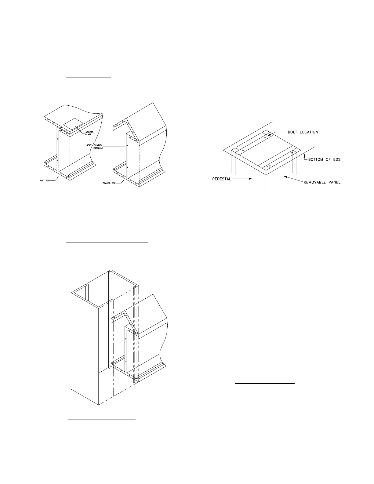
1. Field Joint Detail
Bolt field joint[s] together as shown.
NOTE: Access plates as shown for flat-top unit allows bolts
above partition to be secured. All bolts are ¼”-20. Use flat
washers beneath head of bolt and under nut when bolting
through slots.
2. Control Tower Mounting Detail
Use ¼”-20 bolts between raceway and
control tower as shown on typical
construction below.
beneath head of bolt and under nut
when bolting through slots. Note that
removable panels are facing sides of
raceway. Slots are provided to aid in
ease of assembly. Adjust pedestal so
that it is centered under raceway and
one inch [1”] from end of raceway.
Pedestals under field joints are to be
centered under field joint.
4. Pedestal Floor Mounting Detail
After attaching risors and pedestals
place raceway in position. Level
raceway [shims or spacers may be
required beneath pedestals to
accomplish this] mark position of
holes in bottom of pedestal on floor.
Carefully lift raceway and remove
pedestals to allow installation of
mounting hardware into floor. Use
extreme care to avoid placing lifting
devices across breaker plates as this
will damage lights, switches, knobs or
receptacles. Floor mounting
hardware [not provided by AVTEC]
should be installed in all four corners
of pedestal. Re-attach pedestals to
raceway and lower into position,
bolting through pedestal base into
floor. Use flat washers beneath
heads of bolts used to attach unit to
floor.
3. Pedestal Mounting Detail
Bolt raceway to pedestals with ¼”-20
bolts and nuts. Use flat washers
5. Tower Interface Detail
Place trim collar on tower, Position
tower under hood. Fully tighten trim
collar retaining hardware after the UDS
tower is in proper location. See
diagrams f-1,2,3. See pages 12,13,14.
Page 5
6. Hanging Rod Detail
7.
Locate raceway in position and attach
hanging rod to structural ceiling. Use
turnbuckles to make final adjustments
in raceway height. Level raceway
with level [do not use floor for leveling
purposes, as it may be pitched for
drainage].
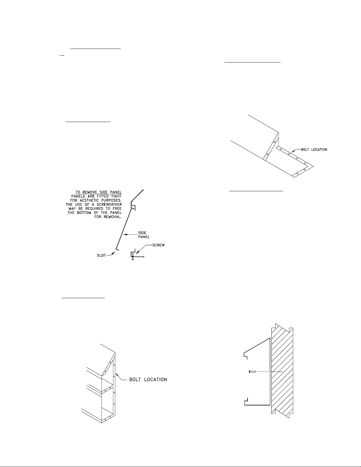
7. Side Panel Detail
The side panels slip fit in place at the
top, #8-32 screws fasten the panel to
the bottom of the housing. The side
panel[s] is installed by fitting the top of
the panel into the top of the housing
and then sliding the bottom of the panel
into position. The #8-32 screws are
then installed into the bottom housing
securing the panel.
B. Wall Mounted Energy Distribution
System
1. Field Joint Detail
Bolt field joints together as shown with
¼”-20 bolts and nuts. Use flat washers
beneath heads of bolts and under nut
when bolting through slots.
2. Risor Mounting Detail
Bolt risor to raceway through flange and
to sloped-top through side of risor with
¼”-20 nuts and bolts. Use flat washers
beneath head of bolt and under nut
when bolting through slots. Square-up
edges before finally torqueing bolts to
present a satisfactory appearance.
3. Wall Mounting Detail
Locate stud centerlines on INSIDE of
unit if mounting to a stud wall. Drill
corresponding mounting holes in the
back of the unit. Care must be taken
to prevent metal shavings from
contacting electrical components.
Vacuum ALL metal fragments
immediately and thoroughly. When
measuring height above finished floor,
be aware that floor may be pitched.
Mark wall through holes, remove unit
and drill into wall for anchors. Avoid
drilling through unit to avoid
accumulations of debris. Secure unit
to wall with quarter-inch [1/4”]
minimum diameter hardware.
NOTE: VERIFY THAT THE WALL IS CAPABLE
OF BEARING THE LOAD.
2
Page 6
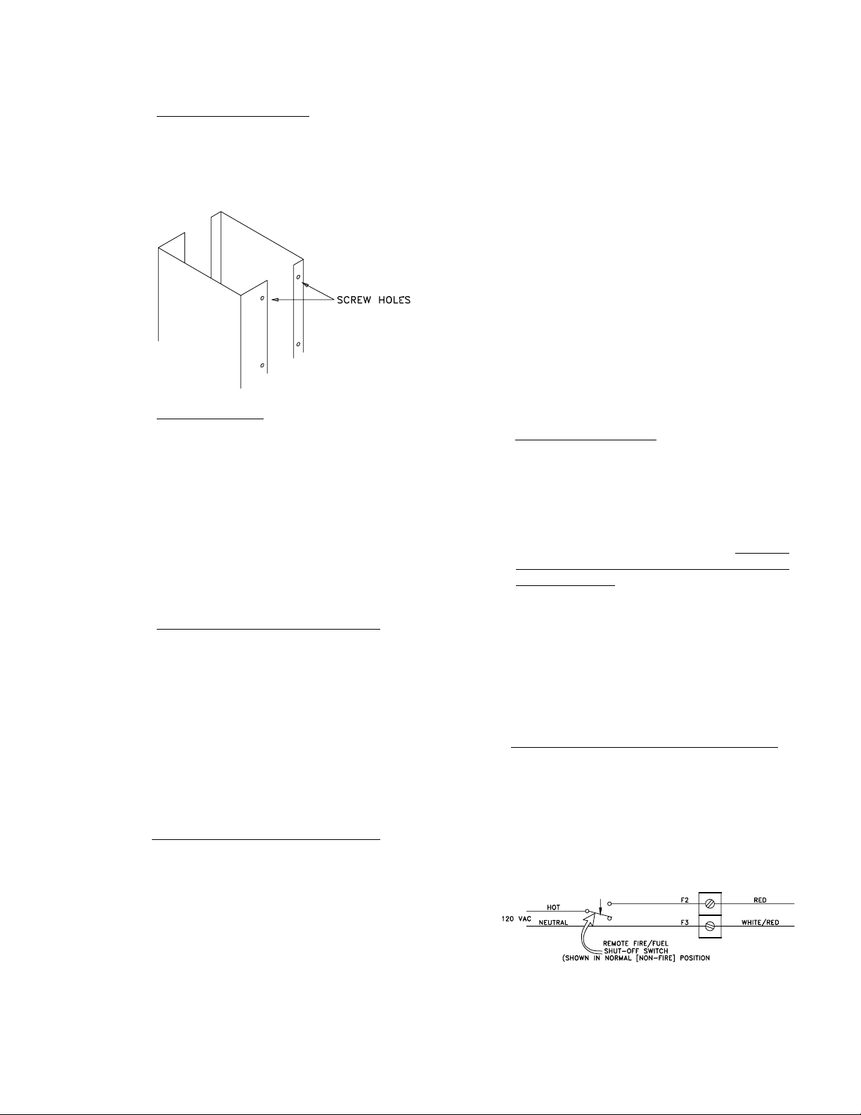
4. Service Enclosure Detail
Mounting the back of the service
enclosure to the wall by drilling through
the back of the housing. Attach front of
enclosure to back with hardware
provided.
5. Side Panel Detail
The side panels slip fit in place at the
top, #8-32 screws fasten the panel to
the bottom of the housing. The side
panel[s] is installed by fitting the top of
the panel into the top of the housing
and then sliding the bottom of the panel
into position. The #8-32 screws are
then installed into the bottom housing,
securing the panel.
C. Plumbing Connection at Field Joints
It is the plumbing contractor’s responsibility
to insure that all unions are tightened and
leaks do not exist. Take care when
tightening unions that they are not loosened
from the pipe. Pipe sealant may be
required to be applied to the face of the
union to prevent leakage. Use care to keep
contaminants and sealant from entering the
pipe where it might cause blockage of traps
and lines when the unit is brought into
operation.
D. Electrical Connections at Field Joints
1. Field joints for bus bar are generally 24”
long sections fastened in four [4]
locations. Note that the field joint
section of bus bar is usually insulated
where possible short spacing may
occur. When bolting down field joint
section, be sure that it makes complete
contact with mating bus bar.
2. Where space limitations prohibit the
use of bus bar, cable bus is used.
Sections of wire with lugs are provided
at field joints. These wires should be
routed through a protective bushing
when they may be subjected to
abrasion.
3. Control circuit wiring at field joints use
quick-connect plug-in connectors.
These can be assembled in only one
way. When more than one connector is
located at a field joint, they should be
different configurations. If not, plug
together the connectors with the same
color wires leading into them. Be
certain that the connections are fully
inserted and that they are making good
contact.
E. Care and Maintenance
The protective coating on the stainless
steel should be removed after installation is
completed. Traces of marking pens can be
removed with careful use of acetone and a
soft cloth. Fingerprints and most stains can
be removed with a soft cloth dampened
with water and mild detergent. The unit
should not be hosed or sprayed with either
steam or water. In order to further seal the
unit, silicone sealant may be applied to the
seams. Annually, the power should be
turned OFF and threaded connections [both
electrical and mechanical] should be
tightened as required.
II. CONNECTION TO REMOTE FIRE-FUEL SHUT
OFF SYSTEM
A. Electrical Shut-Off Detail, No Vent Controls
The AVTEC Electrical Fire-Fuel Shut-Off
System uses a shunt trip circuit breaker[s].
The breakers will trip OFF whenever
120vac is applied to the Red and
White/Red wires [excluding M*** series
style connection plates]. A single main shut
off shunt trip breaker may be used in lieu of
individual shunt trips.
3
Page 7

B. Gas Fire-Fuel Shut-Off Systems, No Vent
Controls
The AVTEC Gas Fire-Fuel Shut-Off System
uses constant 120vac power supply to hold
open an electrically operated solenoid
valve[s]. There is a delay of approximately
1-1/2 seconds built into the system which
holds the circuit [internal to the raceway]
closed in the event of a momentary power
loss. [The Gas Solenoid Valve[s], however,
will close for the duration of the power loss.]
Upon application of power to the Black and
White/Red wires, a horn will sound and a
yellow LED will light, indicating that power
is available for the gas solenoid[s] and
warning that the pilot light[s] will have to be
lit on the accompanying cooking
equipment. The gas solenoid[s] will open
and gas flow begins when the fuel reset
button is depressed.
III. STEAM VALVE TIMER
A. Valve Installation
The Steam Valve consists of three (3)
assemblies. 1. The motor, 2. The linkage
and 3. The steam valve body. Instructions
for assembling and adjusting these parts
are provided in the shipping boxes [except
when the Valve is an integral part of the
raceway, in which case the valve is
assembled at the factory]. The valve is
intended to shut OFF the flow of steam to a
particular area [or perhaps one particular
raceway] upon completion of the work day.
The amount of equipment involved is
dependent upon placement of the valve. A
manual valve should be installed parallel to
the motorized steam valve [as shown in the
accompanying drawing] so that the steam
equipment could be made operative in the
event of an electrical malfunction. In the
event of a power loss, the valve remains in
the position it was in at that time.
C. Gas and Electric Fire-Fuel Shut-Off Detail
When both Gas and Electric Fire-Fuel ShutOff options are used, a form “C” [SPDT]
switch can be employed. The contact
which is held open during normal [non-fire]
operation is connected to the Red wire and
the contact which is held closed during
normal [non-fire] operation is connected to
the Black wire. The neutral to complete the
120vac circuit is connected to the
White/Red wire.
B. Steam Purging System
In most applications, the AVTEC raceway is
equipped to constantly remove condensate from
the steam supply line as it accumulates. In units
with a condensate return line this condensation
is routed to the condensate return line. On units
without a condensate return line, this
condensation is routed to a drain.
C. Start Up
After the raceway and valve are installed and
steam is available, the steam trap should be
removed. Steam should then be allowed to flow
through the unit, flushing the lines of any debris
which may have accumulated during installation.
This debris is removed by opening the ball valve
leading to the steam trap. After the lines are
cleared, the steam should be shut OFF and the
steam trap assembly re-installed. It is
imperative that the lines be flushed before any
4
Page 8

equipment is used and before the steam trap
assembly is put into operation to void damage
by large pieces of debris [pipe dope, metal
chips, etc.] Every effort should be made to keep
the inside of the pipes clean.
D. Timer Operation
The timer is a single channel circuit electronic
programmable time control. Instructions for
programming the timer are enclosed in this
folder. Turn ON the circuit by pressing in the
circuit breaker. Note the Light Emitting diode
[LED] on the door. When the Motorized Steam
Valve is fully open, the LED is green and when it
is fully closed the LED is red.
IV. REMOTE BREAKER STATUS INDICATOR
LIGHTS (E-Series only.)
A. Operation and Function
As an optional feature, remote LED’s can
be located in a more accessible area. The
number immediately above the LED
indicates the corresponding breaker plate
location. These LED’s glow Red when the
breaker is OFF and Green when the
breaker is ON. W here there are future
electrical connections, the LED’s remain
unlit. Note that these LED’s do not
whether or not there actually is equipment
connected nor does it indicate if the
equipment, if connected, is ON or OFF,
merely whether the breaker is ON or OFF.
B. Power Supply
Power for the LED’s is provided by a
transformer which steps down the line
voltage to 24vac. That power is further
reduced by a resistor and rectified by a
diode which is built on to each breaker
connection plate. The transformer is
protected by a fuse[s].
V. GROUND FAULT EQUIPMENT PROTECTION
[GFEP] (E-Series only.)
A. Operation and Function
GFEP is designed to protect pieces of
equipment from damage due to loss of
current to ground. It operates by sensing
the amount of power being delivered to the
equipment and the amount of power
returning to the raceway. Any imbalance
greater than 0.5 amps will cause the circuit
breaker to trip OFF. [In some cases where
the voltage and amperage is low enough to
indicate
allow, the GFEP trip amperage may be as
low as 0.15 amps.] It is necessary to have
all power conductors [including the neutral
wire where appropriate] passing through
the center of the current sensor the same
number of times and in the same direction
relative to line and load. A “Push to Test”
button is provided on each unit.
At initial start up, the equipment should be
disconnected and the circuit breaker turned
OFF. With the equipment turned OFF, it
should be connected and the breaker
turned ON. If the equipment trips the circuit
breaker, immediately [or as soon as the
equipment if turned ON] disconnect the
equipment and check it thoroughly. If the
equipment trips the circuit breaker during
operation, immediately disconnect the
equipment and have it checked thoroughly.
Repeatedly turning ON a breaker
connected to a piece of equipment which
has a ground fault or a short circuit can
damage the ground fault sensor.
When checking the equipment, bear in
mind that conditions can change while the
equipment is in use, and the problem may
not exist after the equipment has cooled.
B. Power Supply
The GFEP receives 24vac power from the
same transformer as the Breaker Status
Indicators. If you suspect that the GFEP
has been damaged, and the circuit breaker
connection plate will not reset, you can
check this by turning OFF the 24vac
transformer, and removing the 10 amp
fuse. If the breaker will then reset, but
turns OFF again as soon as the control
circuit transformer is repowered, then the
current sensor should be replaced. If,
however, the circuit breaker will not reset,
even with the control circuit transformer
turned OFF, then most likely, the problem is
either the fire-fuel shut-off remote wiring or
circuit breaker itself is damaged. Note that
when checking the GFEP, the equipment
should be disconnected.
VI. BREAKER CONNECTION PLATE
A. Nomenclature
When referring to a connection plate, use
the Reference Number and UDS Model No.
[e.g., MIDE999999A] and the connection
[enclosed in this folder]
5
Page 9

[#1E, 2E, etc.]. The connection plate can
be further identified by including the
amperage and the voltage/phase. The
model no’s. connection plates are shown
below.
X X XXX XX XXX
[1] [2] [3] [4] [5]
[1] Model Number
L “L” or “M” series
E “E” series
[2] Type
F Electric fire shutoff (Model “E” Only)
G GFEP (Model “E” Only)
H Electric fire shutoff and GFEP (Model
“E” Only)
I GFCI (Only used with 20 amp breaker
single pole 120v/1 phase)
J Electric fire shutoff and GFCI (Model
“E” only: same as “I” in usage)
N Plate with receptacle only
X Electric (No f/f GFEP of Aux switch)
[3] Amperage
15 15 amp A = 1 pole
20 20 amp B = 2 pole
30 30 amp C = 3 pole
40 40 amp
50 50 amp
60 60 amp
80 80 amp
100 100 amp A,B, C not used
[4] Voltage/Phase
03 120v/1 phase
23 208v/1 phase
24 208v/3 phase
14 120/208v/1 phase
15 120/208v/3 phase
43 480v/1 phase
44 480v/3 phase
45 277/480v/3 phase
Note: #’s 43, 44 & 45 only used on “E”
series, 3 pole.
[5] Receptacle
Straight blade receptacle
AR
Switch and straight blade receptacle
AS
No receptacle
BO
Turn and lock receptacle
CR
Duplex convenience outlet, straight blade
DC
Switch only, used only 20 amp 1 pole
SW
Flexible seal tite conduit (pigtail)
P
Note:
Add “W” to #5 for watertite cover.
Pigtail is “special,” pigtails do not get
watertite covers.
B. Operation
The Circuit Breaker is turned ON by means
of a lever actuator located behind an
optional hinged cover. When plugging
equipment into the receptacle the breaker
should be OFF. Insert cordset fully into
receptacles and turn to secure into position
[twist/lock outlets only]. Some
receptacle/plug types have a locking collar
which should be tightened. Twist/lock type
plugs and receptacles will require care
upon insertion to prevent the natural
straightening tendency of the cord from
unlocking the plug from the receptacle.
C. Installation and Replacement
The breaker connection plate assembly is
held in position by four (4) or six [6] #8-32 x
½” stainless steel screws. It is attached to
the bus by wires and is connected to the
control circuit harness by means of a 6-pin
quick-connect plug which provides power
for the LED indicator and Fire-Fuel ShutOff, Ground Fault Equipment Protection
and/or remote lights.
VII. REMOTE GAUGES AND VALVES
A. Installation
As an option, ½” Male NPT
temperature/pressure gauges may be
provided for hot water, cold water and
steam supply incoming services. When
provided, gauges are located near the
incoming service to the raceway by the
plumbing contractor.
B. Purpose
The temperature/pressure gauges are
intended to provide information on the
quality of services; i.e., whether or not there
is sufficient pressure or if the hot water, for
example, has lost too much heat en route
to the raceway.
VIII. VENTILATOR LIGHT SWITCH
In some cases, a switch and circuit breaker
is provided which controls the lights in the
hood above the equipment. A ten ft. [10’0”] length of ½” flexible conduit is provided
with three wires [black for hot, white for
neutral, green for ground] for connection to
a junction box above the ventilation unit.
This flexible conduit can be trimmed to
6
Page 10

length in the field by the electrical
contractor.
IX. STEAM SUPPORT MODULE [Kettle Arm]
A. Installation and Connection to Raceway
The kettle arms are attached to the
raceway by bolts and on non-cantilevered
units to the floor by short legs. It is
imperative that the arms and kettles [or fry
pans] be level and bolted to the floor during
installation. Flexible conduit and/or cable
are provided on kettle/arm assemblies
manufactured by AVTEC for electrical
connections and pipe or hoses for plumbing
connections. Refer to schematics for proper
connection.
B. Water Meter
A water meter may be provided as an
option to regulate the amount of water
used. The water meter is a microprocessor
based counter. Instructions for its use are
on a label affixed to the panel in proximity
to the counter. The Green button starts the
flow of water by opening an electrically
operated solenoid valve. The Red button
will stop the flow of water at that point.
While the meter is stopped, the desired
number of gallons can be set by adjusting
the dials to the appropriate digits. As the
water flows through the flowmeter, the
display will automatically countdown,
constantly indicating the number of gallons
remaining. When the display reaches 000
it will automatically shut OFF the flow of
water. A switch is provided marked “FreeFlow” and “Metered.” In the “Metered”
position, the flow of water is regulated by
the Water Meter. In the Free-Flow position,
the solenoid valve is electrically held open
which allows an unlimited flow of water. In
the event of an electrical power loss, the
flow of water will cease as there will be no
power to hold the solenoid valve open.
C. Electronic Cooking Timer
An electronic timer may be provided as an
option. It is used to display time remaining
when cooking a particular product. After
the heat level has been set, the time [in
hours and minutes] is set on the display
similar to the manner used on the Water
Meter. The Green button starts the timer.
The timer may be stopped at any time by
pressing the Red button. When the display
reaches 000, a horn sounds for
approximately five seconds.
D. Cook/Chill
As an option, an electrically operated
Cook/Chill feature can be provided, through
a series of solenoid valves. With the switch
in the “Cook” position, the steam supply
and condensate return solenoids are
opened and the coolant and drain solenoids
are closed. In the “Chill” position, the
7
Page 11

coolant and drain solenoids are open and
the steam supply and condensate return
solenoids are closed. With the switch in the
center position, all solenoid valves are
closed. To Cook in a kettle after it has
passed through the Chill cycle, it may be
expeditious to open the kettle jacket drain
to remove coolant. Kettles may be
equipped with an optional drain solenoid
which allows for removal of the fluid within
the kettle jacket whenever the switch is in
the "OFF” position.
X. CORDSETS
A. Sizing and Connection to Equipment
Cordsets provided by AVTEC include a
strain relief grip for attachment to the
equipment. The length of cord may be
trimmed at the time of installation by the
electrical contractor in order to present a
neat appearance and prevent excessive
lengths of cable from resting on the floor.
Care should be taken, however, especially
on mobile items, to allow enough slack to
allow the operator to move the equipment
far enough to disconnect it from the raceway
without stressing the connections.
B. Connection to Raceway
The plug for connecting to the raceway
receptacle is generally one of three types:
Straight Blade, Twist/lock, and Locking
Collar.
E. Motorized Steam Control
A motorized steam valve control can be
provided as an option on some kettle/arm
assemblies. This valve is controlled by a
knob which in turn operates a motor. This
to to permit mild warming or rapid heating
of the product, or anywhere in between.
This feature can be used in conjunction
with the Cook/Chill option when the latter is
in the “Cook” position. The control plate is
not graduated as heating potential varies
greatly depending on steam pressure and
temperature.
Be sure that the plug blades are fully
inserted into the receptacle in order to
prevent arcing and escessive heating. On
twist/lock plugs, care should be taken to
make sure that the natural straightening
tendencies of the cable do not cause the
plug to twist out and loosen away from the
receptacle. On plugs equipped with a
locking collar, be sure that the collar is
tightened on to the receptacle, thus
drawing the blades fully into the receptacle
and insuring proper contact.
C. Care in Operation
When moving equipment, turn off the
breaker and disconnect the plug from the
receptacle before reaching the limit of the
cordset. Excessive strain can cause
damage to the plug and/or receptacle and
present a very serious situation. If
problems arise because of operator abuse,
you may consider securing the equipment
8
Page 12

to a tether which limits the travel before the
7cable is strained. When cleaning the
equipment, it should be OFF and the circuit
breaker turned OFF before disconnecting
the cordset. Though the cable is oil
resistant, solvents should not be used to
clean the cordset. Use a moist cloth and
mild detergent. Be sure that all parts are
dry before re-connecting the equipment to
the outlet.
D. Nomenclature
Error! Not a valid link.
Model No.
50
24 - AN 6
[1[ [2[ [3] Cable length in ft.
[1] Amperage
20 20amp
30 30amp
50 50amp
60 60amp
80 80amp
100 100amp
[2] Voltage/Phase
03 120v/1φ
23 208v/1φ
24 208v/3φ
14 120/208v/1φ
15 120/208v/3φ
43 480v/1φ
44 480v/3φ
45 277/480v/3φ
[3] Plug Type
AN Straight Blade Straight Cap
BN Straight Blade Angle Cap
CN Twist Lock Straight Cap
DN Twist Lock/Water Tight/Straight
Cap
EN StraightBlade/Water
Tight/Straight Cap
XI. FLEXIBLE HOSE
A. Connection to Equipment
One end of the hose is provided with a union for
connecting to the equipment. Care should be
taken to prevent sharp bends in the hose while
in its operating position and when the equipment
is moved for cleaning and/or service. Elbow,
nipples, etc., may be necessary to accomplish
this.
B. Connection to Raceway
On water lines the raceway is equipped with
quick-disconnect fittings. The supply side is
female for hot water and male for cold water.
Both sides are equipped with shut off valves
which automatically close when disconnected on
water quick disconnects.
On gas lines the raceway is equipped with a
female quick-disconnect which incorporates an
automatic shut off valve which closes when it is
not connected. The raceway also has a manual
ball valve to further ensure that there is no flow of
gas. The male half of the quick-disconnect is
attached to the hose and does not have an
automatic shut off feature. [The double shut off
option is, however, available for use with
manifolded equipment fed by a looped service].
Hoses for steam lines have an insulation layer to
reduce heat flow to the outer braiding. The outer
surface, however, does get hot when in use, so
caution should be used. The raceway is
equipped with a ball shut off valve only. A union
and close nipple can be added between the hose
and ball valve to further facilitate assembly. Take
care to avoid twisting the hose when connecting
the hoses.
C.Care and Maintenance
The hoses can be cleaned easily with a damp
cloth and mild detergent. Do not place undue
stress on the hose when moving equipment.
D.Nomenclature
Model No.
075
G S 48
[1] [2] [3] [4]
[1] Diameter
025 - ¼”
038 - 3/8”
050 - ½”
075 - ¾”
100 - 1”
0125 - 1-1/4”
[2] G GAS
W WATER
SM STEAM
[3] S Stainless Steel Braid [All hoses]
P Stainless Steel Braid with
Polytec [plastic] Coating
9
Page 13

N NSF Potable Water/Steam
[4] Length in inches [12” increments]
XII. DRAIN HOSES
Flexible drain hoses may be supplied as an
option. These are supplied with a union at one
end for connection to the ventilator and a
smooth pipe extension to be inserted into the air
gap drain. The length of pipe between the
ventilator and the drain hoses will determine the
amount of penetration into the air gap. [which
should be just above the flood level, but kept to
a minimum to reduce splash].
10
Page 14

XIII. PARTS LIST
ENERGY DISTRIBUTION SYSTEM – ELECTRICAL
“L” OR “M” SERIES BREAKERS
AVTEC PART NO. DESCRIPTION
EL BRK 0301
EL BRK 0302
EL BRK 0303
EL BRK 0304
EL BRK 0305
EL BRK 0306
EL BRK 0307
EL BRK 0308
EL BRK 0309
EL BRK 0364
EL BRK 0310
EL BRK 0311
EL BRK 0312
EL BRK 0313
EL BRK 0371
EL BRK 0315
EL BRK 0316
15 amp, 240v, 3F, 3 pole, BQ3B15
15 amp, 120v, 1F, 1 pole, BQ1B15
15 amp, 240v, 1F, 2 pole, BQ2B015
20 amp, 120v, 1F, 1 pole, BQ1B020
20 amp, 240v, 1F, 2 pole, BQ2B020
20 amp, 240v, 3F, 3 pole, BQ3B020
30 amp, 120v, 1F, 1 pole, BQ1B030
30 amp, 240v, 1F, 2 pole, BQ2B030
30 amp, 240v, 3F, 3 pole, BQ3B030
50 amp, 120v, 1F, 1 pole, BQ1B050
50 amp, 240v, 1F, 2 pole, BQ2B050
50 amp, 240v, 3F, 3 pole, BQ3B050
60 amp, 240v, 1F, 2 pole, BQ2B060
60 amp, 240v, 3F, 3 pole, BQ3B060
80 amp, 240v, 3F, 3 pole, BQ3B080
100 amp, 240v, 1F, 2 pole, BQ2B100
100 amp, 240v, 3F, 3 pole, BQ3B100
“E” SERIES BREAKERS
AVTEC PART NO. DESCRIPTION
EL BRK 0318
EL BRK 0319
EL BRK 0376
EL BRK 0320
EL BRK 0321
EL BRK 0322
EL BRK 0323
EL BRK 0324
EL BRK 0325
EL BRK 0331
EL BRK 0365
EL BRK 0326
EL BRK 0327
EL BRK 0328
EL BRK 0329
EL BRK 0330
EL BRK 0332
15 amp, 120v, 1F, 1 pole, Circuit Breaker with shunt trip, BQ1B015
15 amp, 240v, 1F, 2 pole, Circuit Breaker with shunt trip, BQ2B015
15 amp, 240v, 3F, 3 pole, Circuit Breaker with shunt trip, BQ3B015
20 amp, 120v, 1F, 1 pole, Circuit Breaker with shunt trip, BQ1B020
20 amp, 240v, 1F, 2 pole, Circuit Breaker with shunt trip, BQ2B020
20 amp, 240v, 3F, 3 pole, Circuit Breaker with shunt trip, BQ3B020
30 amp, 120v, 1F, 1 pole, Circuit Breaker with shunt trip, BQ1B030
30 amp, 240v, 1F, 2 pole, Circuit Breaker with shunt trip, BQ2B030
30 amp, 240v, 3F, 3 pole, Circuit Breaker with shunt trip, BQ3B030
40 amp, 240v, 3F, 3 pole, Circuit Breaker with shunt trip, BQ3B040
50 amp, 120v, 1F, 1 pole, Circuit Breaker with shunt trip, BQ1B050
50 amp, 240v, 1F, 2 pole, Circuit Breaker with shunt trip, BQ2B050
50 amp, 240v, 3F, 3 pole, Circuit Breaker with shunt trip, BQ3B050
60 amp, 240v, 3F, 3 pole, Circuit Breaker with shunt trip, BQ3B060
80 amp, 240v, 3F, 3 pole, Circuit Breaker with shunt trip, BQ3B080
100 amp, 240v, 3F, 3 pole, Circuit Breaker with shunt trip, BQ3B100
20 amp, 480v, 3F, 3 pole, Circuit Breaker with shunt trip, CQD320
-deunitnoc-
11
Page 15

AVTEC PART NO. DESCRIPTION
EL BRK 0333
EL BRK 0338
EL BRK 0334
EL BRK 0335
EL BRK 0336
EL BRK 0337
EL TRN 0304
PB MTR 0401
HD BRK 0310
EL RLY 0325
EL CVR 0328
30 amp, 480v, 3F, 3 pole, Circuit Breaker with shunt trip, CQD330
40 amp, 480v, 3F, 3 pole, Circuit Breaker with shunt trip, CQD340
50 amp, 480v, 3F, 3 pole, Circuit Breaker with shunt trip, CQD350
60 amp, 480v, 3F, 3 pole, Circuit Breaker with shunt trip, CQD360
80 amp, 480v, 3F, 3 pole, Circuit Breaker with shunt trip, CQD380
100 amp, 480v, 3F, 3 pole, Circuit Breaker with shunt trip, CQD3100
Transformer [Control Harness] 120:24v 40va
¾” Water Flow Meter
Current Sensor Bracket
Current Sensor
Breaker Cover
12
Page 16

131415
Page 17

Page 18

Page 19

XIV.WARRANTY
-
WARRANTY-
AVTEC INDUSTRIES INC. warrants to the original purchaser for use of our products, that any part
thereof which proves to be defective in material or workmanship under normal use within one year from
date of installation, will be replaced free of charge, labor to replace such part is warranted for one year
from installation. All warranty labor to be performed during regular working hours, with no overtime
premium.
All W arranty service must be authorized by the factory and be performed by AVTEC’s authorized service
personnel.
This Warranty is limited to the United States and Canada.
This Warranty does not apply to any damage resulting from shipping, improper installation, accident, unauthorized
alteration, local codes not previously brought to the attention of AVTEC, misuse, or abuse; and does not cover loss
of food, other products or damage to equipment or property resulting from mechanical or electrical failure.
AVTEC neither makes nor assumes and does not authorize any other person to assume any other obligation or
liability in connection with its products other than that covered in this Warranty.
16
 Loading...