

Page 1
OPERATOR MANUAL
IMPORTANT INFORMATION, KEEP FOR OPERATOR
This manual provides information for:
THIS MANUAL MUST BE RETAINED FOR FUTURE REFERENCE.
READ, UNDERSTAND AND FOLLOW THE INSTRUCTIONS AND
WARNINGS CONTAINED IN THIS MANUAL.
NOTIFY CARRIER OF DAMAGE AT ONCE
It is the responsibility of the consignee to inspect the container upon receipt of
same and to determine the possibility of any damage, including concealed damage. Unied Brands suggests that if you are suspicious of damage to make a
notation on the delivery receipt. It will be the responsibility of the consignee to le
a claim with the carrier. We recommend that you do so at once.
Manufacture Service/Questions 888-994-7636.
Information contained in this document is known to be current and accurate at the time
of printing/creation. Unified Brands recommends referencing our product line websites,
unifiedbrands.net, for the most updated product information and specifications.
PART NUMBER PP EA0711 REV A (08/11)
1055 Mendell Davis Drive
Jackson, MS 39272
888-994-7636, fax 888-864-7636
unifiedbrands.net
Page 2

Table of Contents
Types of Systems .......................................................................... page 4
Installation Requirements for Avtec Ventilation Hoods .............. page 5
Canopy Hoods ............................................................................... page 5
UV Electrical .................................................................................. page 9
Exhaust Fans & Ducts ................................................................... page 13
Control Panels .............................................................................. page 14
Fresh Air Supply Fans ................................................................. page 14
Side Skirts .................................................................................... page 16
Top Enclosure Panels ................................................................ page 17
Stainless Steel Wall Panels ........................................................ page 18
Operation Instructions Start-Check-Balance ............................ page 19
Final Air Balance Make-Up Air Hood ......................................... page 20
Periodic Maintenance ................................................................... page 21
Parts List ..................................................................................... page 22
Safety Procedures
• Do not attempt to service this unit yourself as removing covers may
cause unnecessary exposure to dangerous voltage.
• Never connect the unit to a power source while standing in water.
Wet hands and wet oors should be avoided when connecting any
electrical appliance to a power outlet.
• Fans may have multiple power connections. Make sure all fans are
isolated from power prior to performing maintenance.
2 OM-ECOARCH
Page 3

In addition, all Avtec/Unified Brands
food equipment is backed by some of
the best warranties in the foodservice
industry and by our professional staff
of service technicians.
Retain this manual for future reference.
NOTICE: Due to a continuous program of product improvement, Avtec reserves the
right to make changes in design and specifications without prior notice.
NOTICE: Please read the entire manual carefully before installation. If certain
recommended procedures are not followed, warranty claims will be denied.
MODEL NUMBER ___________________________________________________
SERIAL NUMBER ___________________________________________________
INSTALLATION DATE ________________________________________________
OM-ECOARCH 3
Page 4
Installation Instructions
TYPES OF SYSTEMS
This manual covers three of the basic types of systems offered by Avtec:
• Baffle Filter
• Modular Grease Extractor
• EcoArch UV
BAFFLE FILTER SERIES
Baffle Filters ventilators are listed by UL and are built in accordance of NFPA-96 for use
with UL listed extinguishing systems for duct hood protection. They utilize UL classified
removable baffle filters to extract grease and provide a limited barrier. The canopy contains
a hidden grease trough and removable cup. Surface, plenum and duct collar extinguishing
systems may be factory supplied.
MODULAR GREASE EXTRACTORS SERIES
Extractor ventilators are listed by UL and are built in accordance of NFPA-96 for use with UL
listed extinguishing systems for duct hood protection. These models utilize high velocity
removable grease extractors. The canopy contains a hidden grease trough and removable
cup. Surface, plenum and duct collar extinguishing systems may be factory supplied.
ULTRAVIOLET (UV) SERIES
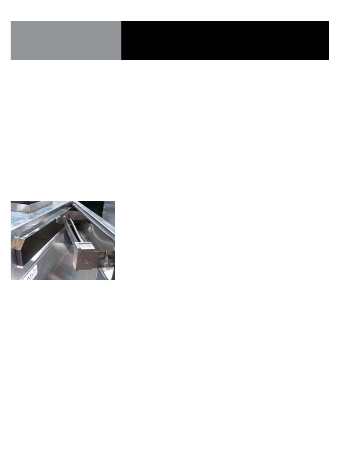
The EcoArch Energy Efficient Ventilation UVc is a door assembly integrally installed in the
exhaust plenum of an EcoArch canopy, consisting of UVc filtration system designed for
use in the ventilation control of commercial cooking operations of listed hood systems. A
depiction of this unit is indicated at left.
The UVc filtration system consists of a Heraus manufactured UVc and Ozone producing
lamp used to reduce exhaust odors and grease deposit emissions before they enter the
exhaust duct system. The UVc light waves and ozone producing lamp breaks the grease
particles into smaller molecules which allow an Ozone reaction to occur chemically. Like
combustion, high temperature separates the O-atoms in atmospheric Oxygen which then
bonds to the grease molecule causing oxidation. Similarly, in UVc technology, the extra
O-atom in the Ozone splits from the ozone molecule and attaches itself to grease molecule
causing oxidation but without the high temperature, which results in the reduction of duct
cleaning, cleaning costs and risks of potential grease fires.
The EcoArch Energy Efficient Ventilation UVc is manufactured with Type 201 Stainless
Steel; but, alternatively can be constructed using 200, 300 and 400 series stainless steel
without adversely affecting the UVc filtration system capabilities.
4 OM-ECOARCH
Page 5
Installation Instructions
Installation Instructions
INSTALLATION REQUIREMENTS
CANOPIES
Avtec hoods are provided with adjustable hanging brackets designed to receive 1/2”
threaded rod with a 1/2” nut and washer. Supporting rods must be connected to all factory
installed brackets. Recommended hanging height is 6’-6” above finished floor for
canopies. Low side wall ventilators should be installed directly upon a Avtec base or on a
rerated wall. If wall mounted, the bottom of the vent should be 36” above finished floor.
ALL AVTEC VENTILATION SYSTEMS MUST BE INSTALLED IN ACCOR-
DANCE WITH NFPA-96, REMOVAL OF SMOKE AND GREASE-LADEN
VAPORS FROM COMMERCIAL COOKING EQUIPMENT.
1. Check all local codes prior to installation. Special requirements may be necessary
depending upon building material construction.
2. Move crated hood to location of installation and very carefully uncrate hood.
3. Raise hood to proper hanging height.
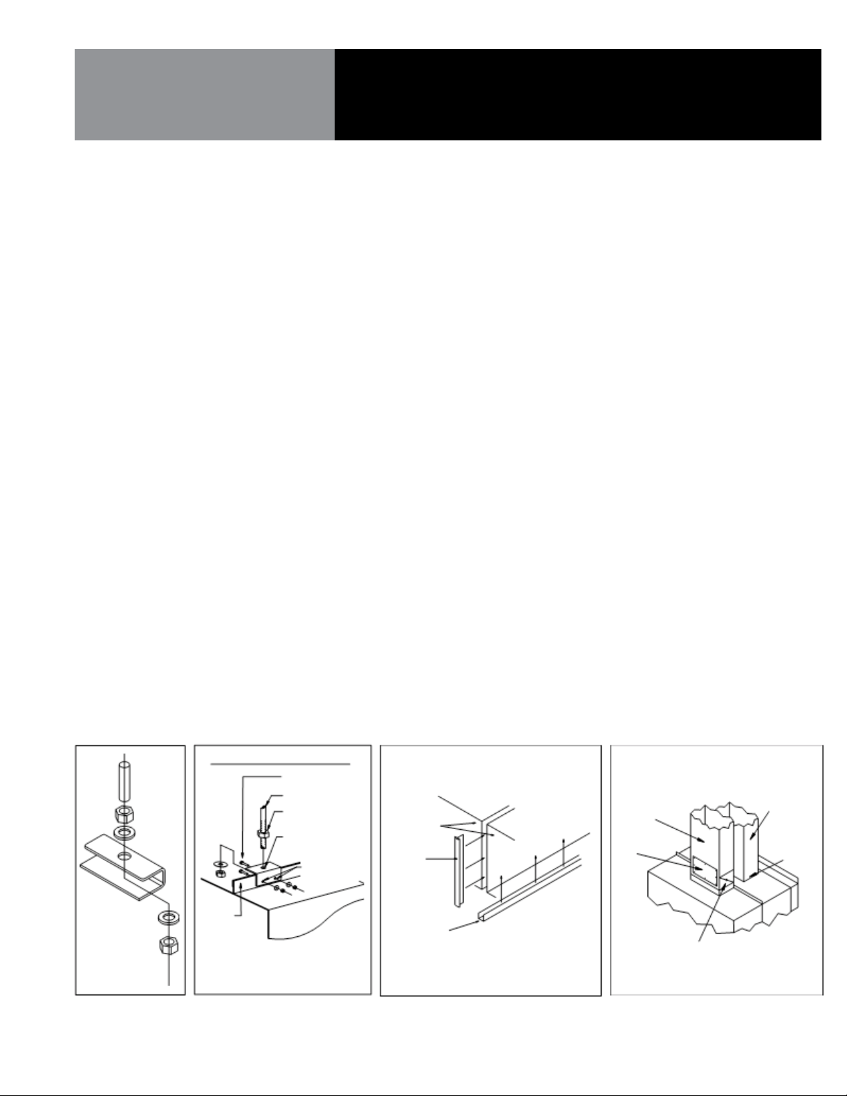
4. Suspend hood from adequate roof supports using 1/2
" threaded rods with nuts
and washers (See Fig. 1).
5. Level hood left to right and front to back.
6. Brackets are provided for hoods which are to be installed end to end or back to back.
Bolt brackets together using 3/8
" bolt through holes provided (See Fig. 2).
7. Install C channel where the ends of the hood meet and install T moldings on front
face of hoods where they join. High temperature silicone can be used to install
channel and T moldings (See Fig. 3).
8. For make-up air hoods, the supply collar with built-in UL listed damper and
air volume damper must be installed per instructions on collar.
9. Provide a removable service door in supply duct near damper (See Fig. 4).
REQUIREMENTS FOR
ALL AVTEC ECOARCH
VENTILATION HOODS
Figure 1 Figure 2
ANGLE
NOTE: HOLES DRILLED THROUGH HOOD ANGLE BY
INSTALLATION
CANOPIES
HANGER BRACKET DETAIL
HOOD
INSTALLER AFTER BRACKET ATTACHMENT
POINTS HAVE BEEN DETERMINED.
S.S. NUT & BOLT
BY OTHERS
HANGER ROD
HANGER ROD
NUT
PRE-DRILLED
HOLE, ACCEPTS
UP TO 1/2"ÿ ROD
OF HOOD
Avtec hoods are provided with adjustable hanging brackets designed to receive 1/2”
threaded rod with a 1/2” nut and washer. Supporting rods must be connected to all
factory supplied/installed brackets. Recommended hanging height is 6’-6” above
finished floor for canopies.
ALL AVTEC VENTILATION SYSTEMS MUST BE INSTALLED IN ACCORDANCE WITH NFPA96, REMOVAL OF SMOKE AND GREASE-LADEN VAPORS FROM COMMERCIAL COOKING
EQUIPMENT.
1. Check all local codes prior to installation. Special requirements may be necessary
depending upon building material construction.
2. Move crated hood to location of installation and very carefully uncrate hood.
3. Raise hood to proper hanging height.
4. Suspend hood from adequate roof supports using 1/2” threaded rods with nuts and
washers (See Fig. 1).
5. Level hood left to right and front to back.
6. Brackets are provided for hoods which are to be installed end to end or back to back.
Bolt brackets together using 3/8” bolt through holes provided (See Fig. 2).
7. Install C channel where the ends of the hood meet and install T moldings on front
face of hoods where they join. High temperature silicone can be used to install
channel and T moldings (See Fig. 3).
8. For make-up air hoods, the supply collar with built-in UL listed damper and air
volume damper must be installed per instructions on collar.
9. Provide a removable service door in supply duct near damper (See Fig. 4).
Figure 3 Figure 4
HOOD FACE
PRE-DRILLED
HOLE, ACCEPTS
5/16" BOLT
T-MOLDING
C-CHANNEL
INSULATED
SUPPLY DUCT
ACCESS
PANEL
FIRE DAMPER &
VOLUME CONTROL
DAMPER
EXHAUST DUCT
FLUID WELD
OM-ECOARCH 5
Page 6

Installation Instructions
ECOARCH CANOPIES EQUIPPED
WITH UV ASSEMBLY
If your EcoArch hood comes equipped with an UV assembly please refer to the following
steps.
General CAUTIONS & Guidelines
• Installation of UV Exhaust canopies must be completed by HVAC ventilation system
contractors or employees trained and qualified to do ventilation hood and exhaust
system installation.
• All Fire Suppression System work must be completed by contractors or employees
trained and qualified to do commercial kitchen exhaust hood fire suppression system
installation.
• All work must conform to local and national building and NFPA 96 codes and
requirements.
• This document covers installation of the UV mechanical components and electric
connections.
• Electric work must be performed by licensed contractors in accordance with the
current National Electric Code and all national, regional and local codes that apply.
• Read and review these instructions BEFORE attempting to install this unit. For
best results, follow the installation sequence…as described.
Follow steps 1-7 as outlined for standard EcoArch canopy installation on page 5.
8. Install grease extractors as shown in (fig. 5 on pages 7-8). Be certain the extractors
are seated properly as the UVc bulb will not operate without safety contacts being
engaged.
9. Open door on face of canopy by twisting the supplied locking handle in order to install
UVc bulb per supplied diagram. Be certain to close door tightly and engage handle latch
in order to engage safety contacts. UVc bulb will not operate without safety contacts
engaged.
10. Check to see that pressure switch tubing is installed on the low port of switch and the
port on top of the hood located in the s/s enclosure.
11. Install power to UV system as described in Electrical section on page 9. See wiring
diagram (fig. 6 on page 10-12).
6 OM-ECOARCH
Page 7
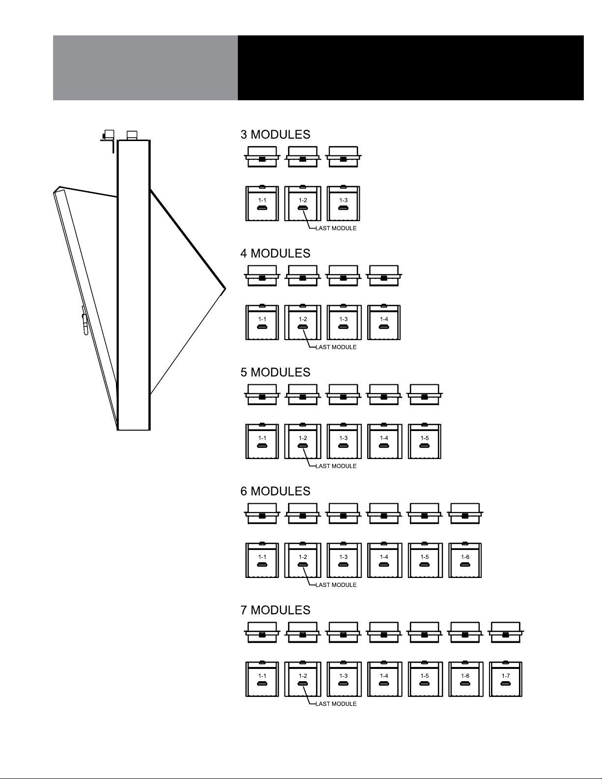
Figure 5
Installation Instructions
OM-ECOARCH 7
Page 8
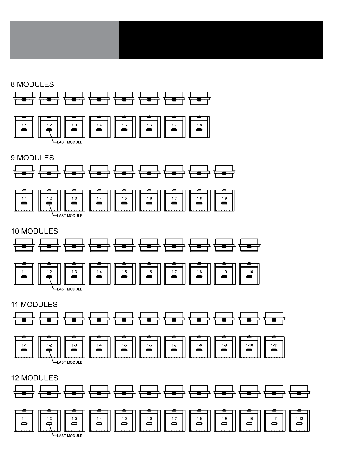
Figure 5 Continued
Installation Instructions
8 OM-ECOARCH
Page 9

Installation Instructions
UV ELECTRICAL
DANGER!
UV LIGHT BULBS GIVE OFF ULTRA VIOLET
LIGHT WHICH CAN BURN YOUR EYES.
ALWAYS USE CAUTION WHEN SERVICING
THE UV SYSTEM.
DANGER!
PLEASE USE CAUTION WHEN INSTALLING
OR SERVICING THE ELECTRICAL SYSTEM
FOR THE UV HOOD. ELECTRICAL SHOCK CAN
CAUSE SERIOUS INJURY OR EVEN DEATH!!!
ELECTRICAL WORK SHOULD ONLY BE DONE
BY QUALIFIED PERSONNEL.
PLEASE ADHERE TO ALL ELECTRICAL
NATIONAL, STATE, AND LOCAL CODES.
Install Power
Locate the relay box on top of the hood. Inside the relay box locate terminal strip 1 (TS-1).
On terminal strip 1 connect a 115/60/1 – 20 amp service to terminals 1 and 2. THE 120V
POWER SOURCE CONNECTED TO THE RELAY BOX IS FOR THE HOOD CONTROL SYSTEM
AND UV LIGHTS ONLY. THIS POWER SOURCE IS NOT FOR THE CANOPY LIGHTS OR FANS.
Those systems require separate power sources.
Control Panel
The control panel will be mounted on the hood or remotely. If the control panel is mounted
on the hood no installation is required. If the control panel is located remotely then
installation is required.
Remote Located Control
• Locate terminal strip 2 (TS-2) in relay box located on top of the hood. This is where
the UV light switch will terminate. THE POWER AT (TS-2) IS 115V/1/60. Connect one
side of the switch to terminal 1 and the other side of the switch to terminal 2. Please
make sure the switch is connected to ground.
OM-ECOARCH 9
Page 10

Figure 6a
Installation Instructions
BALLAST BOX
RELAY BOX
10 OM-ECOARCH
Page 11

Figure 6b
Installation Instructions
OM-ECOARCH 1 1
Page 12

Figure 6c
Installation Instructions
12 OM-ECOARCH
Page 13

Installation Instructions
EXHAUST FAN & DUCT
1. Check all local codes prior to installation.
2. All exhaust fans are supplied with a hinge kit and grease box.
3. The exhaust fan curb should be installed directly above the hood if possible.
Always maintain the shortest duct run possible.
4. Cut hole and seal exhaust fan curb to roof.
5. Duct shall be sized to provide air velocities not exceeding 1200 FPM.
6. Install hinges and airline cable on exhaust fan cap and metal curb. Remember to leave
ample room for fan to tilt back. Fan will remain in tilted back position.
7. Install grease collection box on side of fan that has grease tube discharge.
8. The exhaust duct must be constructed of 16 gauge carbon steel or 18 gauge stainless
steel. All seems must be fluid welded.
9. A duct transition should be provided below exhaust fan inlet.
10. The exhaust duct must be fluid welded to hood collar.
11. Make all necessary electrical connections and check fan for proper rotation.
NOTE: Fan will exhaust air running in wrong direction.
OM-ECOARCH 1 3
Page 14

FOR CONTROL PANEL
(IF PROVIDED)
Installation Instructions
WALL ATTACHMENT
SURFACE MOUNTED
RECESSED MOUNTED
FRESH AIR SUPPLY FAN
(see fig. 7 on page 15)
Control panels optional with all baffle filter type and modular grease extractors.
Control panel dimensions and connection detail are shown on the enclosed shop drawing.
Panels may be surfaced mounted, partially recessed or fully recessed.
Drill four holes in ventilator plumbing compartment as required. Be careful not to damage
any components. Avoid drilling into electrical compartments. Bolt to wall with anchor bolts
or other acceptable means. Weight of control panel varies from 90 to 200 lbs.
Cut hole in wall 1/2” greater than overall dimensions of the control box (shown on shop
drawing). Spacers or support angles may be necessary to provide proper support. It is
recommended that the panel be bolted to wall similar to method used for surface mounted
above.
1. Check all local codes prior to installation.
2. Supply fan inlet must be located to minimum 10’-0” from the exhaust fan. If 10’ is not
possible a 3’ vertical separation may* be acceptable.
3. Cut and seal supply fan curb to roof.
4. Duct shall be constructed of 22 or 24 gauge steel. Insulated duct material should be
used to eliminate frost and/or condensation.
5. Duct shall be sized to provide air velocities not exceeding 1200 FPM.
6. A volume control damper, provided in the duct just above the supply collar that contains
the UL listed re damper, should be properly set to supply CFM required.
7. If the hood is provided without the supply collar installed, it must be installed per the
instructions provided on the collar.
8. Carefully place the supply fan on roof curb. Face supply fan inlet away from prevailing
winter wind. Electrical back draft damper is recommended in cold climates.
9. Bolt or screw fan to fan curb.
10. Make all necessary electrical connections and check fan for proper rotation.
NOTE: Fan will supply air running in wrong direction.
*Dependent on local code requirements.
14 OM-ECOARCH
Page 15
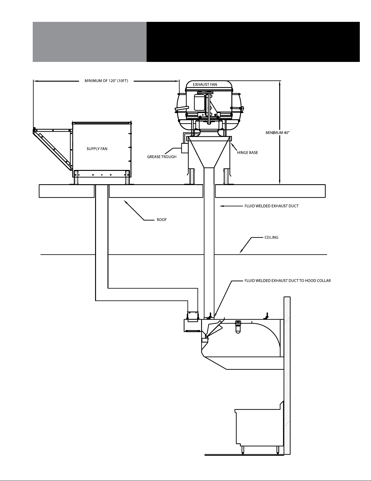
Figure 7
FOR CONTROL PANEL
(IF PROVIDED)
Installation Instructions
OM-ECOARCH 1 5
Page 16

FOR SIDE SKIRTS
Installation Instructions
SIDE SKIRT INSTALLATION
REQUIRED (see fig. 8)
Figure 8
Pieces Provided: One or two side skirts may be provided.
1. Side skirts are offset at the top and have a 90° bend inward at the rear.
2. Skirts are to overlap the outside of the hood. Bolts and acorn nuts should be attached
per the drawing (stainless bolts and acorn nuts supplied).
3. Skirt flange should be screwed to the wall (screws not provided).
16 OM-ECOARCH
Page 17

TOP ENCLOSURES
Installation Instructions
TOP ENCLOSURES INSTALLATION
OF ENCLOSURE PANELS
(see fig. 9)
Figure 9
Pieces Provided: Enclosure panels are provided for exposed side(s) of hood(s).
1. Hoods ordered with enclosure panels will be shipped with clips installed on perimeter
of hood top where panels are to be installed.
2. Slide enclosure panel under clips.
3. If enclosure panels are installed on one or more hoods butted end to end, the butting
ends of the front enclosure panels should be bolted together.
OM-ECOARCH 1 7
Page 18

INSULATED STAINLESS
STEEL WALL PANELS
Installation Instructions
Pieces Provided: Insulated wall panel comes in multiple pieces.
INSULATED WALL PANEL
1. Install wall panels prior to hanging hood(s).
2. Install first panel at one end. Top of panel should be installed 6’-6” A.F.F. and level.
Screw panel to wall.
3. Install any additional panels
4. Caulk vertical seam with NSF approved silicone sealant.
5. When hood is hung it will rest on top panel.
NOTE: Be careful to not damage wall panel face when installing hood.
SINGLE THICKNESS WALL PANEL
1. Install wall panels prior to hanging hood(s).
2. Install seam strips at proper locations and screw to wall.
3. Apply glue to wall between seam strips.
4. Slip one end of wall panel into seam strip, pull out middle of panel and slip other end
of panel into other seam strip. Gently apply pressure over entire wall panel to secure to
wall. Wall bands for side walls are provide with 1” return bend, which is to be located
behind rear wall panels.
18 OM-ECOARCH
Page 19

Start/Check/Balance
DIRECT DRAW HOODS
1. Close all doors and windows.
2. Operate all exhaust fans, even fans serving other hoods, make-up air units and building
HVAC.
3. Turn on all cooking equipment under the hood to preheat to operating temperature.
4. Produce large quantities of smoke.
5. Observe capture of vapors.
6. If all vapors are not captured, increase exhaust fan RPM.
7. Check air pressure in kitchen. Pressure must be negative relative to dining room
pressure.
8. Air velocities entering the kitchen from the dining room should not exceed 100 FPM.
No air should be moving toward the dining area.
9. Repeat steps 6 and 7 until all vapors are captured.
10. Same as step 7 with bottom of next page.
MAKE-UP AIR HOODS
Exhaust Fan(s)
SUPPLY FAN OR
MAKE-UP AIR UNIT
NOTE: The exhaust and supply (if any) air flow rates were established under
controlled laboratory conditions, and greater exhaust and/or lesser supply air may
be required for complete vapor and smoke removal in specific installations.
1. Open all doors and/or windows leading to outside.
2. Start the exhaust fan only. Do not run the supply fan or make-up unit.
3. Refer to drawings and/or UL information label on hood for proper CFM requirements.
4. Adjust speed of exhaust fan to obtain proper air velocities and CFM through grease
filters.
1. Start the supply fan and/or make-up unit only. Do not run the exhaust fan.
2. Refer to drawings or UL information label on hood for proper CFM requirements.
OM-ECOARCH 1 9
Page 20

Final Air Balance
MAKE-UP AIR HOODS
1. Close all doors and windows.
2. Operate all exhaust fans even those serving other hoods, supply fans, make-up air unit
and building HVAC system.
3. Turn on all cooking equipment under the hood and preheat to operating temperature.
4. Produce large quantities of smoke or steam.
5. Observe capture of vapors.
6. If all vapors are not totally captured, fine tune the system by adjusting the air volume
control damper installed in the supply collar. Slightly reduce the amount of supply air
directed under the hood until full capture is obtained.
20 OM-ECOARCH
Page 21

Periodic Maintenance
WARNING
ELECTRICAL SHOCK HAZARD! DISCONNECT
POWER BEFORE SERVICING. REPLACE ALL
PARTS AND PANELS BEFORE OPERATING.
FAILURE TO DO SO CAN RESULT IN DEATH
OR ELECTRICAL SHOCK.
CAUTION
MAKE SURE ALL COOKING EQUIPMENT, THE
EXHAUST HOOD AND UVC EXHAUST AIR
CLEANER HAVE BEEN TURNED OFF AND
ALLOWED TO COOL. HOT EQUIPMENT CAN
CAUSE BURNS.
CAUTION
USE STEP LADDER OR OTHER STABLE
PLATFORM TO PROVIDE EASY ACCESS TO
THE INTERIOR OR THE UVC LAMP CABINET.
DO NOT STAND ON COOKING EQUIPMENT
TO SERVICE THE UVC. FALLS CAN CAUSE
SERIOUS INJURIES.
1. Baffle Filters
Filters should be removed and cleaned at least weekly, depending on hours of operation.
Filters may be cleaned by soaking in a strong detergent solution or running thru a
dishwasher. When replacing, make sure filters and handles are running vertically, and
filters are seated properly.
2. Modular Grease Extractors
Modules should be removed and cleaned at least weekly, depending on hours of
operation. Modules may be cleaned with a brush and a strong detergent solution or
run thru the dishwasher. When replacing modules, make sure they are seated properly.
3. Grease Trough
Should be checked weekly for grease build up and cleaned with strong detergent if
necessary.
4. Grease Collection Receptacle
Should be emptied at least once a day and cleaned daily with a strong detergent.
5. Hood Canopy
A. Inside hood canopy should be wiped down as needed. The area at the exhaust
intake openings should be wiped down daily.
B. Inspect inside of extraction chamber at least weekly to insure proper cleaning and
that the trough and access door are free of foreign matter.
6. UV Preventative Maintenance
Clean the UV lamp at the same time the grease extractors are being cleaned (or daily),
wipe down the UV lamp exterior using a dry towel and a non-detergent cleaning agent
such as sanitizing solution or white vinegar.
IMPORTANT: Do not allow cleaner to run into lamp fittings or socket enclosures.
IMPORTANT: UV System will not work properly without daily cleaning of the UV lamp.
OM-ECOARCH 2 1
Page 22

EcoArch Parts
ITEM NO. AVTEC PART NO. DESCRIPTION
1 HD HDL010 4” Chrome Handle
2 AS SEAL395 3/8” Quickseal
3 AS GLB0201 Incandescent Work Light Globe
4 AS FIX0201 Incandescent Work Light Cage
5 AS LGT1220 3’-0” Fluorescent Work Light
6 AS LGT1420 4’-0” Fluorescent Work Light
7 AS LGT1020 2’-0” Fluorescent Work Light
8 AS LGT9901 Recessed Incandescent Work Light
UV Parts
ITEM NO. AVTEC PART NO. DESCRIPTION
1 AS SEAL1001 Sight Glass
2 EL BLS1101 Ballast, UVC Lamp, 115V
3 EL CNT1104 Connector, UV Lamp
4 EL CON1001 Magnetic Contacts
5 EL FUS0205 1 amp Fuse
6 EL FUS0307 10 amp Fuse
7 EL FUS1101 3 amp Fuse
8 EL GRM1101 Grommet, UV Lamp Socket Heat Resistant
9 EL RLY0327 IDEC Base
10 EL RLY0801 24V IDEC Relay SPDT
11 EL SCK1101 Socket, UV Lamp
12 EL SCK1102 Socket Retaining Nut, UV Lamp
13 EL SWT1001 Door Safety Switch
14 EL SWT1003 Airflow Proving Switch
15 EL TRN0304 24V Transformer
16 EL TUB1101 Lamp, 150W UV
17 HD HDL0601 Locking Door Handle
18 HD HIN2078 Hinge
19 IN GSK1105 Gasket, UV Door
Parts List
22 OM-ECOARCH
Page 23

Service Log
Model No: Purchased From:
Serial No: Location:
Date Purchased: Date Installed:
Purchase Order No: For Service Call:
Date Service Performed Performed By
OM-ECOARCH 2 3
Page 24

1055 Mendell Davis Drive • Jackson MS 39272
888-994-7636 • 601-372-3903 • Fax 888-864-7636
unifiedbrands.net
© 2011 Unified Brands. All Rights Reserved. Unified Brands is a wholly-owned subsidiary of Dover Corporation.
PART NUMBER PP EA0711 REV A (08/11)
 Loading...