

Page 1
Aeronautical Navigator
COCKPIT DOCKING STATION INSTALLATION GUIDE
Standard and OEM Versions
Your Journey, Our Technology
Page 2

Page 3

Aeronautical Products EKP V Docking Station
DISCLAIMER & WARNINGS
This product is not TSO-certied and have received no EASA or FAA approval. This
product is not intended for installation in type-certicated aircraft.
Avoid installing the product near heat sources or ensure adequate cooling is
provided. Avoid routing of the wiring near sources of heat, RF or EMI interference.
The included USB GPS antenna is not suitable for external use. Install and securely
x the antenna inside the cockpit with the dome pointing towards the sky. For better
performance ensure the antenna has a clear view of the sky.
The Docking Station is designed to operate when docked into the cockpit. Handle
the device with care when it is not installed and do not attempt to lock the EKP V
unit.
OVERVIEW
This document provides basic instructions for the installation and use of the EKP V
Docking Station. The Docking Station package contains:
• EKP V Docking Station
• USB GPS antenna (“Mouse GPS antenna”)
• Flush Mount Kit
• Plastic Protective Cover
• Manual, screws and cutting template
Installation Guide - 3
Page 4
Aeronautical Products EKP V Docking Station
4 - Installation Guide
Aeronautical Products EKP V Docking Station
Installation Guide - 5
General Description
The EKP V Cockpit Docking Station (CDS) allows the installation of AvMap EKP V
Aeronautical Navigator into the cockpit, and enables the unit to interface to multiple external
devices at the same time.
When docked the EKP V is powered/charged by the aircraft electrical system.
XM WX Weather
Receiver
Traffic
Receiver
CONNECTIVITY
Autopilot
External
GPS
A2 ADAHRS
Module
Cockpit integration with
Docking Station
Page 5

Aeronautical Products EKP V Docking Station
Installation Guide - 5
Dimensions and Specifications
Versions:
• Standard (UX0DS100AM) : including the wire clamp board adapter.
• OEM (UX0DS200AM): including a DB15 adapter for direct wire soldering
Interfaces:
• 4 x USB 2.0 ports
(1 x battery powered by EKP V internal),
• 2x Serials ports
(1 x RS-232, 1 x TTL levels),
• Audio IN,
• Audio OUT,
• Video IN
(video composite signal PAL or NTSC),
• Push-To-Talk
• Power input voltage:
10-35 VDC (28 W max.),
• Temperature range -20, + 70 °C.
B
C
A
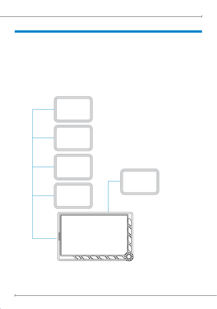
Front Side
A Male Pogo Pin connector, to be coupled with the female connector on the back side of the EKPV.
B Fuse: Socket for the 3A fuse.
C Safety switch to disable the power supply to the connector (A) when the device is not docked.
Page 6

Aeronautical Products EKP V Docking Station
6 - Installation Guide
Aeronautical Products EKP V Docking Station
Installation Guide - 7
Back Side
D Battery powered USB Port: backup power provided by the EKP V internal battery.
E Normal USB Ports: powered by the aircraft electrical system.
F DB 15 direct soldering connector (OEM version only).
G Wire clamp connector (Standard version only).
H Cable locking bar.
F
Back Side - OEM Version
G
Back Side - Standard Version
D
D
E
E
H
Page 7

Aeronautical Products EKP V Docking Station
Installation Guide - 7
Wiring and connections
USB Ports
The CDS includes four USB ports to connect AvMap's or approved third-party modules
to the EKP V. One of the ports (D) is powered by the EKP V internal battery to ensure
functionality even in case of aircraft electrical power failure.
Battery powered USB Port:
backup power provided by
the EKP V internal battery.
Standard Version DB-15 Connections
External Power Supply Input (10-35Vdc)
Push to Talk
Video Input
Audio Input
Audio Output
Serial Interface “A”
(Note: RS232 polarity and levels)
Serial Interface “B”
(Note: 0-5v levels and RS232 polarity)
Page 8

Aeronautical Products EKP V Docking Station
8 - Installation Guide
Aeronautical Products EKP V Docking Station
Installation Guide - 9
OEM Version DB-15 Connections
DB-15 electrical pin-out DB-15 Connections
8
15
9
1
Pin # Signal
GND - EXT
1
GND
2
AUDIO-VIDEO GND
3
AUDIO IN
4
AUDIO VIDEO GND
5
RXA
6
GND
7
TXB
8
EXT+
9
PUSH TO TALK
10
VID-IN
11
AUDIO OUT
12
GND
13
TXA
14
RXB
15
External Power Supply Input (10-35Vdc)
GND - EXT
1
EXT+
9
Video Input
VID-IN
11
AUDIO-VIDEO GND
3
Audio Input
AUDIO VIDEO GND
5
AUDIO IN
4
Audio Output
AUDIO OUT
12
AUDIO VIDEO GND
5
Serial Interface “A”
(Note: RS232 polarity and levels)
TXA
14
RXA
6
GND
13
Serial Interface “B”
(Note: 0-5v levels and RS232 polarity)
TXB
8
RXB
15
GND
7
Push to Talk
PUSH TO TALK
10
GND
2
Page 9

Aeronautical Products EKP V Docking Station
Installation Guide - 9
CDS Installation
OEM Version Standard Version
Cut the cockpit using the cutting template 1.
provided in the box.
Connect and secure the included DB-15 2.
interface (direct soldering or clamp board,
depending on the CDS version) on the
back of the CDS.
Connect required wires to DB-15 3.
connection, as explained in the previous
chapter.
Connect USB cables and secure them 4.
with the included safety lock bar.
Install the docking station in the cockpit 5.
hole and secure it with the ush mount
braked. Push the bracket in the center and
ex it until it is possible to lock it with the
provided nuts.
Fasten and secure the wires to the back of 6.
the CDS, to avoid vibrations or mechanical
stress on the connections.
NOTE: after installing the CDS make sure that all on-board instruments and systems perform
as expected. Verify the on-board compass calibration.
Page 10

Docking the EKP V
Aeronautical Products EKP V Docking Station
A1
A2
1
2
3
10 - Installation Guide
NOTE: when the EKP V is not
docked the CDS can be protected by
installing its plastic protective cover.
Page 11

Page 12

www.avmap.it
www.avmap.us
MMDSXAM0AE031
ÑMMDSXAM0AE031vÓ
 Loading...