

Page 1
Aeronautical Navigator
USER MANUAL
Update Software version
V1.6.069R
Your Journey, Our Technology
Page 2

Page 3

Navigatore Aeronautico AvMap EKPVINDEX
1. LEARN BEFORE USE 4
I. Safe temperature range 4
II. Battery and power source recommendations 4
III. Warning 4
IV. Unit setup 5
V. Powering Up the unit 5
2. Initial Settings 6
3. General controls to operate the unit 7
I. Button, Joystick and Wheel controls 7
II. EKP V Views 8
4. GPS Page 8
5. Main Menu 9
6. System Setup 9
7. Map Setup 10
8. Explore the Map 13
I. PAN mode 13
II. Map information and cursor menu 13
III. MODE menu on Map 14
9. GoTo - Direct Navigation 14
I. Cursor 14
II. Airport Search 14
III. Other objects 16
10. Tracks 16
11. Flight Plan 17
I. How to create, delete or reverse a FP 18
II. How to assign a name to a FP 18
III. How to add, delete and show-on-map a Waypoint 18
IV. How to change the WP order in a FP 19
V. How to activate and navigate a FP 19
VI. How to change the WP INFO visualized in the WP List Area 19
VII. Howtoshow/hidetheFPVerticalProle 19
VIII. How to activate the Airspace Check function 19
IX. How to create a SAR (Search and Rescue) FP 19
X. How to select an approach 19
12. Approach Plates 19
13. EKP V Simulator 21
14. Tools 22
15. Proles 26
Appendix A: NMEA Data Transfer 29
Page 4

Aeronautical Navigator AvMap EKPV
4 - Quick Manual
Aeronautical Navigator AvMap EKPV
Quick Manual - 5
1. LEARN BEFORE USE
I. Safe temperature range
DANGER: do not operate EKP V beyond
the operating temperature range.
Temperature MIN MAX
Operating
temperature
Storage
temperature*
DANGER: do not store EKP V beyond the
Storage temperature range. Remove the
battery before storage.
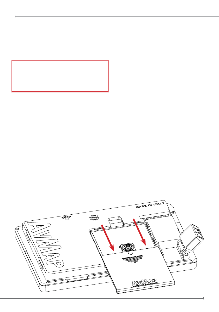
II. Battery and power source
recommendations
EKP V is provided with a Li-Ion rechargeable
battery. The battery compartment is in the
back side of the unit, under the battery cover.
DANGER: Never operate or store EKP V
without the battery cover in place.
DANGER: The battery could explode in
case of improper use or short-circuit.
Battery is recharged connecting EKP V to
a power source using the cigarette lighter
cable or the wall charger.
DANGER: Use only the original cables
provided in the box to power EKP V.
Full charge of battery requires about 6 hours.
EKP V can be operative while charging; in
this case the full charge of battery could take
up to 12 hours.
ATTENTION:
If the battery is completely discharged, it
could be necessary to remove it and then to
power up the unit on external power. Once
the unit is running re-insert the battery.
- 20° C / - 4° F 60° C / - 140° F
- 30° C / - 22° F 80° C / - 176° F
*without battery
III. Warning
The electronic cartography displayed by the
EKP V is not certied for use for VFR or IFR
ights. The EKP aeronautical GPS navigator
is meant as an aid to VFR navigation and is
not a substitute for ofcial PUBLICATIONS,
NOTAM, BRIEFINGS and AERONAUTICAL
CHARTS that must be in any case carefully
consulted before and during any ight.
The information provided by the EKP is GPS
based information which is only intended to
supplement ofcial charts.
All critical ight information is presented for
reference only and must be veried by the
user.
The EKP is not a substitute for on-board
instruments.
The sector MORA values provide a minimum
1000 foot clearance above terrain and
physical obstructions.
Terrain and obstacle data provided are only
to be used as a general reference to your
surroundings and as an aid for situational
awareness.
Street network information has only been
provided with the purpose of reference during
ight and should be used with caution.
The altitude shown by EKP V is the geometric
distance from the sea level based on GPS
data.
XM Weather data is meant to show
atmospheric disturbances in order to select
alternative routes, and not to guide you
through the bad weather conditions.
The Global Positioning System (GPS) is
a space-based global navigation satellite
system operated by the U.S. Government,
which is solely responsible for its accuracy
and maintenance.
EKP V has an internal data logger where
the ight data is recorded. Data logger is not
accessible without disassembling the unit.
EKP V chart and database data are provided
by third parties, included but not limited to
Navteq® and Jeppesen®.
Page 5
Aeronautical Navigator AvMap EKPV
Quick Manual - 5
Cartographic data loaded in the EKP V can
differ from reality. The pilot in command
assumes total responsibility and risk
associated with the use of this device and
remains solely responsible for ying in safe
conditions.
AvMap disclaims any liability deriving from
an improper use of the device, in a way that
may violate the ight and navigation rules,
regulations and safety.
IV. Unit setup
1. Open the battery compartment
2. Insert the Micro SD, if not already
inserted
3. Insert the battery
4. Close the battery compartment door
5. Rotate the GPS antenna to the maximum
sky visibility position.
6. Connect EKP V to a power source for
battery charging:
6.1 Connect the cigar lighter cable with
the label face up to the EKP V side
connector, or
6.2 Connect the USB cable to a PC (slow
battery charge), or
6.3 Connect the USB cable to the wall
charger.
7. The unit will automatically switch on.
V. Powering Up the unit
The EKP V can be powered up both running
on battery or on external power.
When running on battery to power up the
unit press once the POWER button. When
the external power cable is connected either
with battery inserted or not inserted the unit
will automatically switch on.
In the power up phase two consecutive splash
screens will appear. After a few seconds
the second splash screen will be replaced
by the Warning page. To move to the map
press the joystick (ENTER). The EKP V has
been conceived to be always ready to use
through a STANDBY functionality which can
be set by the user.
The user can set a time interval from a
minimum value of 5 min to a maximum of
120 min to enable the function.
The user can put the EKP V manually in
STANDBY by pressing the PWR button
and release the PWR button before the
countdown. To turn off the unit completely
the user needs to keep the PWR button
pressed for more then 3 seconds
When the navigator is in STANDBY, pressing
POWER button it is possible to resume the
unit on the map page. It is suggested to not
Page 6

Aeronautical Navigator AvMap EKPV
6 - Quick Manual
Aeronautical Navigator AvMap EKPV
Quick Manual - 7
power off the unit and to use the STANDBY
functionality. After 8 hours of inactivity the
unit will power off autonomously.
2. Initial Settings
When you power on EKP V for the rst time,
you need to choose some basic settings, in
order to start to use the device.
Language
When you power on the device, you need to
choose rst the language.
The default language is English. If you want
to change language:
1. Scroll down the items until you will nd the
preferred language (see sample image)
2. Push the joystick to select it.
Scroll down the list to select Continue and
push the joystick to go to the next page.
In the next page, you need to choose (see
sample image):
Regional settings
Choosing the regional settings, you select
some basic settings to be used on your
device. You can choose between American
and Other.
Choosing American, you select the following
parameters:
• Temperature: F
• North Reference: Magnetic
• Local Time Difference: -06:00
• Date Format: MM/DD/YY
• Objects overlap: ON
• American Selective Display
• American POI View
Page 7

Aeronautical Navigator AvMap EKPV
Quick Manual - 7
1. Push the joystick to enter in the menu
2. Scroll the joystick up or down to increase or
decrease this difference
3. Push the joystick to conrm and exit.
Display orientation
You can choose between vertical orientation
and horizontal orientation. In order to set the
preferred orientation, choose the item and
push the joystick.
After you have chosen all the required
settings, select the item Continue and push
the joystick to go to the Warning page.
These settings are automatically saved for
the next use.
You can modify these settings in every
moment, using the correspondent menu.
Note: Your settings are stored in the SD
card in the active user prole. Using another
SD card, your settings will be lost.
Choosing Other, you select the following
parameters:
• Temperature: C
• North Reference: True
• Local Time Difference: +01:00
• Date Format: DD/MM/YY
• Objects overlap: OFF
• European Selective Display
• European POI View
In order to use the device in Europe, you
need to choose Other. When the unit is
used in North America you need to choose
American.
Local time difference
You need to set the difference between
the time of the country where you are using
the EKP V and the UTC time. To set this
difference:
3. General controls to operate the unit
I. Button, Joystick and Wheel
controls
F1 – Provides quick access to several
function at user choice
NEAR – Lists nearest objects
MENU – Opens Main Menu page
MAP – Goes back to the Map
ESC – Escapes from one menu page or
menu item to the prior menu
GOTO – Activates navigation to selected
object
FP – Opens Flight Plan Menu
CYCLE – Toggles between various map
presentations
MODE – Change display mode from
Navigation display, EFB, EFIS and Standby
mode
Page 8
Aeronautical Navigator AvMap EKPV
8 - Quick Manual
Aeronautical Navigator AvMap EKPV
Quick Manual - 9
POWER – Turn On/Off, Standby and controls
brightness (press once)
JOYSTICK – Used for PAN the map and
when pressed as ENTER
WHEEL – Used for Zoom In/Zoom out on
the map and for navigating in the Menus
II. EKP V Views
The EKP V software is made by two main
views: Map and Menu.
The Map view is accessed pressing the
map button; it contains the moving-map
representation. Three different congurations
can be selected by the user: Track Up, Leg
Up and North Up.
The Menu view is made by different pages
and contains data and settings.
How to operate in the Map view
Move the joystick to move the cursor on the
map. Push the joystick to open the cursor
menu.
The wheel (or knob) controls the ZOOM
level on the map.
How to operate in the Menu view
The Main Menu bar is available on the top of
the page displayed. Each page has different
areas. To move to an area below the current
one, move the joystick down; to move to an
area above, move the joystick left or press
ESC.
also in the map view by the “satellite” icon.
Three green bars mean a perfect signal
reception, instead the icon made with a red
bar and a WARNING symbol inside a triangle
means that the signal is not present.
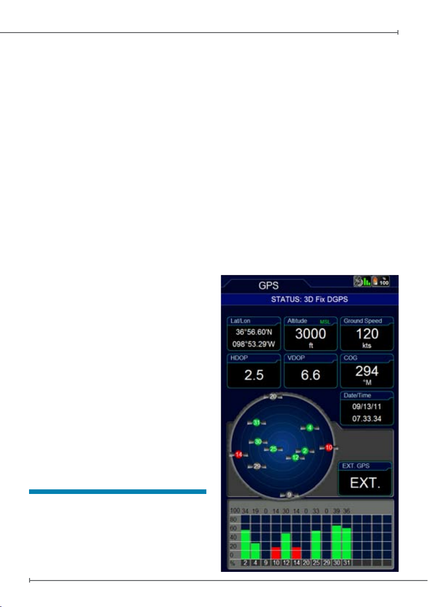
To control the reception status, you need to
access to System Setup menu in the main
menu and select GPS Page.
In this page you can see the signal level for
each satellite and the constellation scheme,
together with additional data regarding the
reception and the position.
In the EXT. GPS box, you can see the
wording EXT. if you are using the external
antenna, while you can see the wording
DIS. if you are using the internal antenna.
WARNING: Global Positioning System is
a system provided and maintained by The
To focus on the desired option use the wheel.
To select a menu item push the joystick.
4. GPS Page
To optimize the GPS antenna reception, we
advise that you open the antenna and keep
it lifted upon a parallel position in reference
to the sky.
The GPS status is displayed in all pages and
Page 9
Aeronautical Navigator AvMap EKPV
Quick Manual - 9
United States of America Government, who
is solely responsible for keeping it working.
AvMap is not responsible for any possible
damage, changes and calculation adjustment
that could affect the data accuracy.
5. Main Menu
Push the MENU button to open the main
menu.
In the top menu bar it is possible to choose
between:
- Map Setup, to change the visualization of
information and objects on the map
- Navigation Setup, to change the
navigation parameters
- Database, to operate on the database of
aeronautical objects and personal data
- Tools, to operate on specic function as
weather, checklist, etc
- Proles, to create and manage different
user settings
- System Setup, to change the general
settings of the EKP V
- About, to check the version of system
components
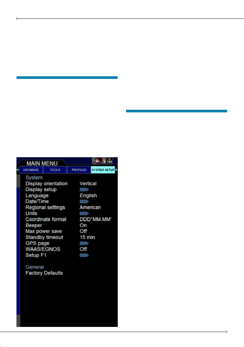
6. System Setup
System Setup menu allows you to set
several basic settings and preferences in
order to customize the unit according to user
needs.
The orientation of the display can be set
as vertical or horizontal. The language can
be changed to the mother language of the
user (default language is English). Regional
settings can be switched between American
and Other.
Also other functions such as the Max Power
Save mode and the Standby Timeout can be
selected in this menu.
Max Power save prole can be used when
it is required to save battery. In this mode,
display is switched off after 10 seconds
since last user action or software command.
Display shall switch on automatically when
software detects a variation of relevant
parameters as speed or when the FP
approaches a waypoint where a maneuver
is requested.
Standby Timeout is the timeout the unit waits
before moving to Sleep Mode when no user
action or input is detected.
F1 Button
Another important feature which can be
accessed through the System Setup Menu
is the F1 button setup.
Page 10

Aeronautical Navigator AvMap EKPV
10 - Quick Manual
Aeronautical Navigator AvMap EKPV
Quick Manual - 11
F1 is a button that can be set up to be
associated with several functions.
In order to set it up:
• Push MENU button and then F1 button
• The list of the possible functions that can
be associated with this button appears on
the screen. Choose the favorite functions
among the listed ones.
• Push ESC button to come back to the
map.
After you set up it, whenever you push F1
button during the navigation, the customized
menu will be opened and using it you will
able to access to all your favorite functions.
If you set up only one function for this
button, F1 will allow you to access directly to
it, without opening a menu window.
7. Map Setup
The Map Setup menu is the rst menu
available in the top menu bar of the main
menu page. In this menu it is possible to
optimise the map details and information
based on the navigational need and
conditions.
Map Visualization:
This section permits to setup maps
presentation, the map orientation and the
auto position mode.
Presentation Setup
The Presentation setup menu gives you
the possibility to setup 3 different map
presentations.
Each Map presentation is dened on Cycle 1,
Cycle 2, and Cycle 3 on users preference.
For each cycle you can select what map
type you want to see, and at the same time
for each map presentation you can choose
what objects and airspaces you want to
enable in that specic map presentation.
Once you setup this menu you can easily
change the visualization of the map by
selecting the CYCLE button. Every time
you touch the CYCLE button the map
visualization will be modied according to
the pre-dened customized cycles.
On the Presentation setup you select for
each Cycle the type of Map to be used:
- Map :
Geographic Terrestrial Background map
with or without Land Elevation (Land
Elevation visualization can be enabled or
disabled in OBJECTS for each cycle).
- TAWS :
Terrain Awareness Warning System.
TAWS highlights safe and unsafe elevation
for an easier to read map display. TAWS
Page 11

Aeronautical Navigator AvMap EKPV
Quick Manual - 11
is a very powerful feature that uses the
separation between the aircraft and the
land elevation to highlight the dangerous
land elevations, allowing the map to be
more easily and readily interpreted. To
enable TAWS function, Land Elevation
needs to be enabled in “objects” . TAWS
has two settings: 500 feet Separation and
1000 feet Separation. The colour shading
is based on Obstacle Clearance Height
(OCH). In case of 1000 feet SEP setting
all terrain with an OCH value under 1000
feet are highlighted in red, while a 500
feet SEP highlights all terrain with an
OCH value under 500 feet.
- Weather (only available in North
America and Canada with XM WX
Weather service):
See chapter “14. Tools” for more
information.
- Sectional Charts:
Only visible in the presentation menu if
Sectional Charts are installed on your
EKP V.
Auto position Mode
Auto Home
The Auto Home mode is used to keep the x
position within the visible map. The map is
scrolled and redrawn automatically as your
position moves. A slow ashing airplane
icon will indicate your current position. The
airplane will be pointing in the direction of
movement. Auto Home can display the
map in North Up, Leg Up or Track Up. To
deactivate Auto home mode press ‘ESC’
activating the cursor at the previous position
Page 12

Aeronautical Navigator AvMap EKPV
12 - Quick Manual
Aeronautical Navigator AvMap EKPV
Quick Manual - 13
or move the joystick to enable the cursor
under the current x position.
Auto Zoom
The Auto Zoom mode is used to keep the
x position and destination (Target) visible
on the map.
The map is scrolled and zoomed
automatically to keep the best view possible.
When this mode is active the cursor is
hidden. To activate Auto Zoom mode press
‘ESC’ in Moving Map. Auto Zoom requires a
position x and an active destination point. If
a destination point is not present it works as
Auto Home mode. To deactivate Auto Zoom
mode press ‘ESC’ activating the cursor at
the previous cursor position or press the
key to enable the cursor under the current
x position.
Map Layout:
In this section it is possible to congure the
layout of the map page. EKP V gives the
possibility to customize in detail the content
of each data eld and its position. Moreover,
it is possible to select and display data elds
both in the vertical and in the horizontal bar.
Select Layout Conguration to modify the
layout of the map page.
There are 3 sections to congure, selecting
each of them on the selecting bar on top of
the menu page:
VerticalProle(VP)
Permits to show or to hide the Vertical
Prole during navigation.
HSI window
Permits to show or to hide the HSI
window.
Page 13

Aeronautical Navigator AvMap EKPV
Quick Manual - 13
Dataelds
The data elds can be hidden or shown in
4 ways; one line, two lines, three lines or
one vertical column.
The scheme shown in this page represents
the map page. The highlighted zone is
the one that you’re going to modify.
To congure one of the options, scroll
with the wheel selector or joystick through
the options. Push ENTER to conrm
the option and check the result on the
scheme shown in the centre of the page.
Objects:
To avoid map cluttering caused by too
many objects, it is possible to select which
objects are shown on the map and which
are hidden.
When using the menu Selective Display it
is possible to pre-dene the visualization of
different objects on different Zoom levels.
8. Explore the Map
II. Map information and cursor menu
When placing the cursor on top of an object,
an information window appears that shows
some object information. To get complete
information of the object, select ENTER.
The cursor menu will appear from which it is
possible to select:
• Objects info, to visualize the information
of the selected object.
• Airspaces, to visualize the information of
the airspaces of the cursor position.
• Add to FP, to add the cursor point (Object)
to the activated Flight Plan.
• Add user point, to save the cursor point
as user point.
• Save as user mark, to save the cursor
point as user point.
• Show zoom lens, to see the objects
I. PAN mode
If the GPS signal is available, the icon of the
aircraft is shown on the map. When moving
the Joystick, the cursor will appear on the
map and you enter in the PAN mode, which
permits you to explore the map and the
shown objects. The cursor is represented by
a round icon with a cross in the centre and
an arrow for orientation. The orientation of
the cursor is always in the direction of your
proper position.
When the GPS signal is missing the icon
made with a red bar and a WARNING symbol
inside a triangle is displayed, the cursor is
shown on the map but the orientation arrow
of the cursor will disappear.
For zooming, touch the wheel selector and
scroll from left to right to ZOOM IN or ZOOM
OUT on the map.
Page 14

Aeronautical Navigator AvMap EKPV
14 - Quick Manual
Aeronautical Navigator AvMap EKPV
Quick Manual - 15
area at a closer zoom level in a separate
window, which makes it easier to select
an object without changing the zoom
level of the map display.
III. MODE menu on Map
During navigation it is possible to change
display mode to EFB mode (Electronic
Flight Bag), PFD mode (Primary Flight
Display) if the AvMap A2 ADAHRS module
is connected to the EKP V, or Navigation
mode to display the moving map.
The EFB page provides quick information
on the departure airport and the destination
airport of the active ight plan, like airport
information and airport Approach Plates.
9. GoTo - Direct Navigation
Direct navigation to an object can be
activated selecting the GOTO button. The
menu permits to choose different types of
destinations. In particular, from the GOTO
menu it is possible to search for a specic
point as destination:
• Cursor
• Airports
• VOR, NDB, Intersections
• Address
• POI
• VFR Rep. Point
• User point
• Lat/Lon
I. Cursor
This is the quickest way to plan a route.
Search for the destination point by exploring
the map with the cursor, place the cursor on
the precise position (use the ZOOM level
to be more precise) and press the GOTO
button. The GOTO menu will appear and
select Cursor. The selected position is
now your destination and the navigation is
immediately active.
II. Airport Search
In the GoTo menu select Airports to search
the destination in the airport and aireld
database. You can search for an:
• ID
• Name
• City
When you enter the airport database page,
the ID eld is highlighted. Select ENTER to
search an ID or scroll down with the Joystick
to search on Name or City.
For Example, scroll down with the joystick
to City and press the ENTER button to
select the City eld. The virtual keyboard will
Page 15

Aeronautical Navigator AvMap EKPV
Quick Manual - 15
Database submenu Aeronautical objects
select Airport pushing the joystick. Select to
search the airport on ID, Name or City of the
airport by pushing the joystick:
1. Select the characters by scrolling the
wheel selector (the selected character is
highlighted).
2. Conrm the desired character by pushing
the joystick.
As a usual keyboard, the virtual keyboard
provide also the tab space button, to create
a space between two characters, the Cancel
button, to delete the last selected character
and the button to change from Alphabetic
keyboard to numeric keyboard (see sample
image).
When the available results in the database
appear.
The Virtual keyboard helps you to write
names and addresses on the EKP V menu’s
and appears on the display every time you
need to enter or modify a name, address or
search for an Airport.
In the round circle you can select the different
characters by scrolling the wheel selector.
In the center of the circle a windows shows
the selected characters and the number of
results found.
Below the circle another section shows a list
of results.
In the following, two examples that
illustrates the use of the virtual keyboard are
presented.
Airport search from the database
In the Main Menu select Database. In the
Page 16

Aeronautical Navigator AvMap EKPV
16 - Quick Manual
Aeronautical Navigator AvMap EKPV
Quick Manual - 17
are 15 or less, the result list below the virtual
keyboard shows the results:
1. Scroll down the list with the joystick or the
wheel selector.
2. Push the joystick to select and conrm the
desired item.
To return to the virtual keyboard push ESC
Note: While selecting the characters,
only the characters that can complete
the available results remain active to be
selected. to be able to insert faster the
characters for its result.
Chooseanameforauserprole
In the main menu select Proles and select
the prole you would like to change the
name to by scrolling the joystick or wheel
selector.
Push the joystick, select Edit name a push
the joystick to conrm. Now you enter the
virtual keyboard page:
1. Use the Cancel button to delete the
characters of the actual prole name. Insert
the new name by selecting the characters
with the wheel selector (the selected
character is highlighted) and conrming the
desired character by pushing the joystick.
2. To insert the new name as prole name
select the OK button by pushing the joystick
down wards.
3. Push the joystick to conrm OK to save
the chosen name and to return to the Prole
menu.
4. If you don’t want to select OK, move the
joystick in any direction to return to the virtual
keyboard or push the ESC button.
In both examples, to exit the virtual keyboard
push the ESC to return to the previous page
within modifying the names.
III. Other objects
As well, it is possible to select other items in the
GoTo list and navigate towards these objects.
10. Tracks
During the navigation, you can record the
track of your ight.
In order to start the recording:
1. In the main menu choose Database
2. In the menu Personal Data select
TRACKS
3. Push the joystick on the option “Start
recording”.
In the page you can see (see image) the
track name (identied by its recording time),
the status, the track points number and the
color by which the track appears on the
map.
Page 17

Aeronautical Navigator AvMap EKPV
Quick Manual - 17
• Hide the track and all the recorded
tracks.
11. Flight Plan
FP page
You can store up to 50 Flight Plans (FP) in
your EKP V at the same time. Only one FP
can be shown on the map at any time.
To access the FP Page press the FP button
on the keyboard.
FP Page is divided in 4 areas, top down:
• FP Tab Area, containing the list of the
available FPs.
• FP Information Area (not selectable),
containing info on the selected FP
The track can be in three different status:
recording phase (identied by a green dot),
visible on the map (eye-shaped icon) and
hidden on the map (eye-shaped with a red
cross icon).
You can nish the recording, pushing the
joystick on the option “Stop recording”.
Pushing the joystick on the track name, you
have access to several options:
• Edit the name
• Edit the track color
• Choose the track line width (to increase
or decrease the thickness of the track on
the map)
• Hide the track (in this way it’s no more
visible on the map)
• Delete the track
Page 18

Aeronautical Navigator AvMap EKPV
18 - Quick Manual
Aeronautical Navigator AvMap EKPV
Quick Manual - 19
• WP List Area, containing the list of the
WP of the selected FP.
• VP Area (not selectable), containing the
info of the Vertical Prole along the FP.
To move from FP Tab Area to WP List Area
move DOWN the Joystick, vice versa move
LEFT the Joystick or press ESC.
I. How to create, delete or reverse a FP
To create a FP select Add FP in the FP Tab
Area.
The virtual keyboard is visualized: write the
desired name for the FP and select OK on
the virtual keyboard.
A FP tab with the assigned name will appear
in the FP Tab Area.
To delete a FP, select it in the FP Tab
Area, press ENTER and choose the option
Delete.
To reverse a FP, select it in the FP Tab Area,
press ENTER and choose the option Reverse.
II. How to assign a name to a FP
Select a FP in the FP Tab Area, press ENTER
and choose the option Edit Name. Write the
desired name and conrm selecting the OK
on the virtual keyboard.
III. How to add, delete and show-onmap a Waypoint
There are two methods to add a Waypoint
(WP) to a FP:
• In the FP page select ADD WP in the WP
List Area and choose the kind of WP to
add. Available options are: Airport, VOR,
Page 19

Aeronautical Navigator AvMap EKPV
Quick Manual - 19
NDB, Intersection, User Point, Address
or Lat/Lon.
• From the map, move the cursor to the
desired location and press ENTER.
Choose the option Add to FP: a WP with
the selected location will be added to the
active FP.
To delete a WP, select it in the WP List
Area, press ENTER and choose the option
Delete.
To show-on-map a WP, select it in the WP List
Area and choose the option Locate on Map.
IV. How to change the WP order in a FP
Select the WP which must be moved in the
WP List Area, press ENTER and choose
the option Change Order pressing ENTER.
Change the WP position using the Joystick
UP/DOWN or the knob (counter clockwise)
and conrm pressing ENTER.
V. How to activate and navigate a FP
To start the navigation on a FP, it must be
active.
To activate a FP, select it in the FP Tab Area
and choose the option Activate/Deactivate.
A green icon is shown in the FP Information
Area of the active FP.
VI. How to change the WP INFO
visualized in the WP List Area
In the WP List Area there are three
information elds per each WP.
By default setting, the info elds are
Bearing, Distance and ETA (Estimated Time
of Arrival).
To change the content of the info elds,
select a FP in the FP Tab Area and choose
the option Setup data elds.
In the Data Fields window select the desired
information to be displayed in each column.
It’s not possible to display the same info in
more than one column.
Press ESC button to go back to FP page.
VII. How to show/hide the FP Vertical Profile
Select a FP in the FP Tab Area and choose
Show/Hide Vertical Prole. A new Area
displaying the Vertical Prole of the ground
along the FP will appear/disappear at the
bottom of the FP page.
VIII. How to activate the Airspace
Check function
To visualize the list of airspaces intersected
by a FP, select the FP on the FP Tab Area,
press ENTER and choose the option FP
airspace check.
Press ESC to go back to FP page.
IX. How to create a SAR (Search and
Rescue) FP
Create a new FP, select it in the FP Tab
Area, press ENTER and choose the option
Add SAR FP.
Choose one of the three available patterns,
set the desired characteristic and press
ENTER to conrm each parameter. Select
Create SAR option to create the FP.
The WP list is created automatically starting
from the current position depending on the
chosen pattern.
X. How to select an approach
Select a FP with an airport as nal destination
as your active FP. Press the FP button and
access to the FP menu. In the FP tab Area,
press ENTER and choose the option select
approach. The list of approaches for the
destination airport is shown. Select one
approach scrolling the list using the joystick
or the wheel. Go back to the map and the
legs for the selected approach are shown on
the map.
12. Approach Plates
Depending on your chart coverage the
Page 20

Aeronautical Navigator AvMap EKPV
20 - Quick Manual
Aeronautical Navigator AvMap EKPV
Quick Manual - 21
Approach Plates on EKP V are represented
by Airport Diagrams, Instrument Approach
Procedure (IAP) Charts and Visual Approach
Procedures (VAP) Charts.
With these Approach Plates the EKP V can
be used as a digital booklet to substitute the
paper charts. (see example).
The images are Geo-referenced meaning
that during ight your actual position is
visualized on the chart image.
It is possible to visualize an Approach Plate
(also without GPS signal) in different ways:
Airport Database:
1. Enter the Airport Database
2. Select an Airport
3. Scroll with the joystick or the wheel
selector down to the options bar.
4. Scroll with the joystick or the wheel
selector to PLATES and push the Joystick
to conrm.
5. Scroll with the joystick or the wheel
selector up and down in the items list.
6. Select the desired item and push the
joystick to visualize it.
From the Map:
1. Place the cursor on top of the desired
airport and push the joystick to conrm
the object selection.
2. Choose the option Show Objects Info
3. In the Airport Menu Scroll with the joystick
or the wheel selector down to the options
bar.
4. Scroll with the joystick or the wheel
selector to PLATES e push the Joystick
to conrm.
5. Scroll with the joystick or the wheel
selector up and down in the items list.
Page 21

Aeronautical Navigator AvMap EKPV
Quick Manual - 21
6. Select the desired item and push the
joystick to visualize it.
From Flight Plan:
1. Push the FP button
2. Select the desired Flight Plan move
the Joystick downwards to enter the
waypoint list
3. Select an desired airport in the
waypoints list
4. Push the joystick to open the airport
option page
5. Select Full Info
6. In the Airport Menu Scroll with the
joystick or the wheel selector down to
the options bar and select PLATES.
From MAP button:
When the selected destination is an Airport,
it is possible to visualize the Approach Plates
of this airport pushing the MAP button.
Once one AP is selected from the list,
pushing MAP button the same AP will be
shown.
If the nal destination is changed a new AP
shall be selected.
shown.
Push ESC to return to the Approach Plates
list in the Airport database page.
13. EKP V Simulator
It is possible to setup a ight simulation of
a route or a ight plan, selecting speed and
other parameters, even if the GPS signal is
not available.
To start a simulation, access to the Main
Menu and select the Navigation Setup submenu. Using the joystick move to Simulator
item and press ENTER. A new window will
appear where Simulation can be activated
and some parameters modied. Press
In all cases, while visualizing the Approach
Plates, it is possible to:
• Change ZOOM level of the image
scrolling the wheel selector clockwise
(two ZOOM IN levels). Scroll the wheel
selector counterclockwise to ZOOM OUT.
When zooming the same position of the
cursor on the image is kept in case x is
not available. If x is available, the zoom
is centered on x position.
• Pan the image on the display by moving
the joystick
• Visualize the list of available Approach
Plates related to the selected Airport by
pushing ENTER and use the joystick or
the wheel selector to select a new item.
Pushing ENTER the selected item is
Page 22

Aeronautical Navigator AvMap EKPV
22 - Quick Manual
Aeronautical Navigator AvMap EKPV
Quick Manual - 23
ENTER on Simulation and modify from
Off to On. Then press ESC to go back to
Navigation Setup menu or MAP to move
directly to the map.
14. Tools
In the Tools menu the connection setup of
external devices to the EKP V are managed,
like:
- External GPS
- Autopilot
- XM weather
- Trafc
- EFIS
- Video In
EKP V has one USB input connection on
the cigarette lighter power cable to connect
one external device. When used with the
Cockpit Docking Station, it is possible to
connect several external devices to the EKP
V through the Cockpit Docking Station. The
Cockpit Docking Station has 2 serial input
(COM A and COM B) and 4 USB input. For
more details on the Cockpit Docking Station
visit www.avmap.it.
For each external device the connection
interface needs to be conrmed in the
dedicated tools menu selecting COM A,
COM B or USB.
External GPS
When installed in the Cockpit Panel of the
aircraft it is recommended to use the EKP V
external GPS antenna (included in the box
content of the Cockpit Docking Station and
available as additional accessory) with the
EKP V to get a good GPS reception. The
EKP V external GPS antenna needs to be
connected to the USB port on the Cockpit
Docking Station.
For connection instructions see the EKP V
Docking Station Installation Guide included
in the EKP V Docking Station box and
available at www.avmap.it.
Autopilot
Most third-party autopilots common used in
aviation are compatible with EKP V. For a
compatible list of third-party autopilots visit
www.avmap.it.
NMEA output
To enable autopilot communication with
the EKP V activate the communication of
information in the TOOLS Menu by selecting
Autopilot and turning on the NMEA output.
Connection Interface
The autopilot can be connected to COM
Page 23

Aeronautical Navigator AvMap EKPV
Quick Manual - 23
A, COM B of the Cockpit Docking Station
through serial connection. When connected
to the USB port the EKP V USB-Serial
converter cable needs to be used.
For connection instructions through the
Cockpit Docking Station see the EKP V
Cockpit Docking Station Installation Guide
included in the EKP V Docking Station box
and available at www.avmap.it.
Select NMEA Messages
Select the NMEA message to communicate
with the autopilot. See appendix A for a
description of the NMEA messages.
Baudrate
Select the Baudrate conform the requested
setup of the external device.
XM Weather
In North America the meteorological service
XM Weather is available, which is compatible
with the EKP V with respect to the following
products:
• NEXRAD
• Lightning
• Precipitation
• METAR
• TAF
• TFR
To enable the XM WX feature, simply
connect the device to the EKP V through
USB connection and activate the reception
of information in the TOOLS Menu by
selecting XM Weather and turning ON the
Page 24

Aeronautical Navigator AvMap EKPV
24 - Quick Manual
Aeronautical Navigator AvMap EKPV
Quick Manual - 25
RECEPTION and conrming the connection
interface to USB, COM A or COM B.
When connected to the USB port the EKP
V USB-Serial converter cable needs to be
used.
For serial connection instructions through
the Cockpit Docking Station see the EKP V
Cockpit Docking Station Installation Guide
included in the EKP V Docking Station box
(also available at www.avmap.it) and the
serial connection specication of the ZAON
XRX trafc receiver (ZOAN XRX Manual).
The Range option allows you to select the
horizontal detection range. The available
option range are 6 NM radius, 3 NM radius
and 1,5 NM radius.
To increase accuracy, different airframe
DATA RECEPTION and conrming the
connection interface to USB.
Make sure the Weather is enabled in
Presentation setup in the MAP SETUP
menu. If Weather is not enabled in the
presentation setup, the unit may still receive
the XM signal, but it will not be displayed on
the map.
Trafc
EKP V is compatible with ZAON XRX trafc
receiver.
To enable the trafc feature, connect the
trafc receiver device to the EKP V through
USB or Serial Connection (COM A or COM
B) connection and activate the reception
of information in the TOOLS Menu by
selecting Trafc and turning ON the DATA
Page 25

Aeronautical Navigator AvMap EKPV
Quick Manual - 25
types have different characteristics that
effect the antenna reception pattern of the
ZOAN XRX.
Select the Aircraft type of your aircraft to get
the best performance of ZOAN XRX. For
more information on Aircraft Type set-up
check the ZOAN XRX Manual.
Note:
Select “Prole 1” on the ZAON XRX “COM”
menu to enable communication with the
EKP V.
EFIS
Connecting AvMAP A2 ADAHRS (Air Data,
Attitude and Heading Reference System),
EKPV turns into an EFIS.
The A2 connects to the docking station via
USB and provides the user with:
• Attitude (roll, pitch and heading angle)
• Airspeed
• Altitude
• Wind Estimation
• Side slip indication
• Vertical Speed
These information are collected and
displayed to the pilot on the EKP V screen,
when Primary Flight Display mode (PFD
Mode) is selected. For more details on the
EFIS user interface see AvMap A2 ADAHRS
User manual included in the A2 ADAHRS
box and available at www.avmap.it.
Note: Although this user guide assumes the
use of a Docking Station, it is also possible
to connect the A2 module to the USB port of
Page 26

Aeronautical Navigator AvMap EKPV
26 - Quick Manual
Aeronautical Navigator AvMap EKPV
Quick Manual - 27
the EKP V cigarette-lighter cable.
Video In
The Cockpit Docking Station includes a
video input (NTSC and PAL) that allows
connecting the EKP V to video cameras with
very useful applications for tail-draggers, or
monitoring ights!
In the VIDEO IN menu you can select “show
video” to see the video on the display. Adjust
saturation, contrast, brightness and hue
phase to personal requisition.
The Video can also be activated selecting
this option for the F1 button.
Device Manager
The Device manager conrms what
application is connected to the EKP V,
through which device and it shows the
status whether the application is enabled or
disabled.
Checklists
The checklist is the traditional list of actions
to be performed before, during and after
each ight.
EKP V has a few pre-congured checklist,
but it is possible to customize an existing
checklist or to create a new one.
How to create a Checklist
Select Add Checklist in the top bar in the
Checklist page.
Enter a name for the checklist using the
virtual keyboard and conrm clicking OK.
Scroll the top bar and select the newly
created checklist, press ENTER and then
select Edit.
The following options are shown:
• Add new item, to add an item (the name
of the item can be further edited selecting
the item and pressing ENTER);
• Save and Exit, to save the actual
checklist;
• Delete All, to delete all items in the
checklist;
• Exit without save, to close without
saving;
• Edit, to modify the name of the checklist;
• Delete, to delete the checklist.
A pre-arranged checklist can be modied,
selecting Edit at the bottom of the list itself.
15. Profiles
The user prole allows you to store all your
favorite settings to use your device in a very
customized way.
You can create several proles: this
possibility is very useful if the same device
Page 27

Aeronautical Navigator AvMap EKPV
Quick Manual - 27
is used in different congurations or if it is
used by several users: every pilot can save
his personal prole.
You need to access the User Prole menu
from the main menu. In the page you can
see all the user proles available in the
device, with their name and creation date
(see sample image).
Addaprole
In order to add a new user prole:
1. Select Add Prole by pushing the joystick
2. Choose if you want to create the new
prole from the default settings or from
an already existing prole.
3. The virtual keyboard is opened:
• Insert the prole name
• Scroll down the joystick to select OK
• Push the joystick to conrm and go back
to the proles menu
Activateaprole
The active prole can be recognized by the
green highlighted rectangle-shaped icon in
the number column. In order to activate a
prole:
1. Select the prole by using the joystick
2. Push the joystick to conrm
3. Select the Activate option
WARNING: all the modications made to
the settings are recorded in the active user
prole.
Please note:
The active prole cannot be deleted.
When selecting the active prole it is possible
to Reset this prole to defaults settings: this
option allows you to go back to the factory
settings.
Modifyaprolename
In order to change the prole name:
1.Select the prole by using the joystick
2.Push the joystick
3.Choose the Edit option
4.The virtual keyboard is opened:
• Insert the prole name
• Scroll down with the joystick to select OK
• Push the joystick to conrm and go back
to the proles menu
Copyaprole
In order to copy a prole:
1. Select the prole by using the joystick
2. Push the joystick to conrm
3. Choose Copy option
4. The virtual keyboard is opened:
• Insert the prole name
Page 28

• Scroll down with the joystick to select OK
• Push the joystick to conrm and go back
to the proles menu
Deleteaprole
In order to delete a prole:
1. Select the prole by using the joystick
2. Push the joystick to conrm
3. Choose Delete option
Note:
When you power on the device for the rst
time, you will nd a default user prole in
the user proles menu, which contains the
factory settings (PROFILE01).
Note:
User proles are stored in the micro SD,
so using another SD you will loose your
proles.
Aeronautical Navigator AvMap EKPV
28 - Quick Manual
Page 29

Navigatore Aeronautico AvMap EKPV
Appendix A: NMEA Data Transfer
The bi-directional data port outputs and inputs NMEA Data. NMEA messages sent/received,
are dened as follows:
APA Autopilot Sentence “A” contains navigation receiver warning ag status, cross-
trackerror, Waypoint arrival status and initial bearing from origin Waypoint to the
destination Waypoint for the active navigation leg of the journey.
APB Autopilot message contains all of the above plus: heading to steer toward destination,
bearing from the present position to the destination (magnetic or true).
GGA GPS position, time, x quality, number of satellites used, height of antenna, HDOP
(Horizontal Dilution of Precision), differential reference information and age.
GSA GPS receiver operating mode, satellites used in the navigation solution reported by
the $— GGA sentence.
GSV Number of satellites in view, satellite numbers, elevation, azimuth, and SNR value.
RMB Data status, Cross Track Error, direction to steer, origin, destination Waypoint,
Waypoint location, bearing to destination and velocity toward the destination.
RMC Time, Latitude, Longitude, Speed Over Ground, Course Over Ground and date.
XTE Cross-Track Error
For information about the NMEA format specications: www.nmea.org.
Page 30

www.avmap.it
www.avmap.us
MQEK5AM0AE080
ÑMQEK5AM0AE080HÑ
 Loading...