

Page 1
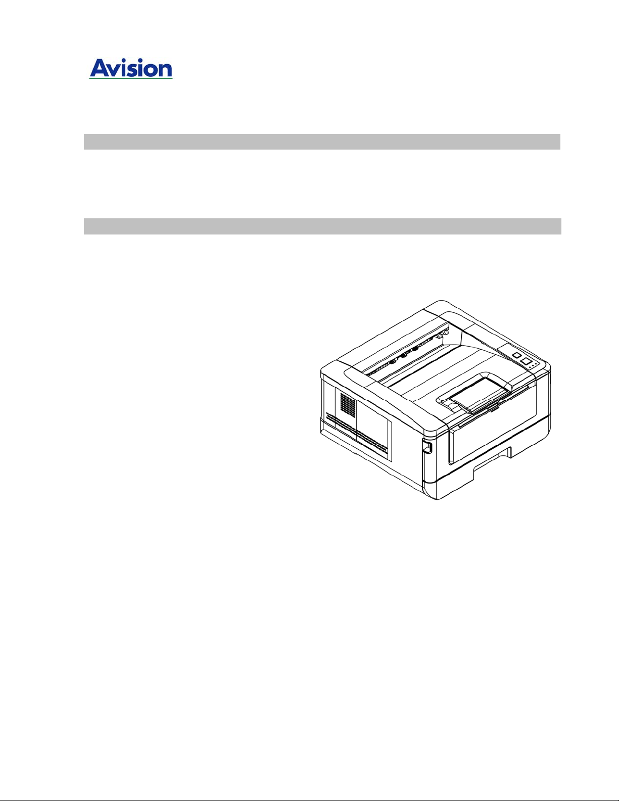
A4 Digital Printer
AP30 Series User's Guide
Avision Inc.
Page 2

User’s Guide
Safety Information
When using this equipment, the following safety precautions should always be followed.
Safety During Operation
In this manual, the following important symbols are used:
WARNING:
Indicates potentially hazardous situations, wh ich if instructions are not followed, could result
in death or serious injury.
CAUTION:
Indicates a potentially hazardous situation which, if instructions are not followed, may result
in minor or moderate injury or damage to property.
Important:
Indicates operational requirements and restrictions. Please read and follow these
instructions to ensure a proper operation and to avoid damage to the machine.
Note:
Indicates further explanation or clarification. Reading this is highly recommended.
WARNING:
To avoid hazardous electric shock or fire, do not remove any covers or screws other than
those specified in this manual.
CAUTION:
To reduce the risk of fire, use only no.26AWG or larger telecommunication line cord.
Disconnect the power plug by pulling the plug, not the cable.
Do not touch the metal fingers of the ADF pad module. The edges are sharp and
touching them may result in injury.
ii
Page 3

SAFETY INSTRUCTION
This printer is a page printer which is operated by means of a LSU (Laser Scanning Unit)
printhead. There is no possibility of danger from the LSU printhead, provided the printer is
operated according to the instructions in this manual. Since radiation emitted by the LSU
printhead is completely confined within protective hou sings and external covers, the LSU
beams cannot escape from the machine during any phase of user operation.
Do not place a coffee cup, vase, or other liquid-filled container on the machine.
Spillage can damage the machine’s electrical parts and insulation.
Take care not to drop paper clips, staples, or any other metal objects into the machine.
When clearing paper jams, refer to the instructions in this manual.
Before disconnecting the plug, turn the machine off. Make sure your hands are dry.
Hold the plug itself, not its cord, when disconnecting it from the receptacle.
Never attempt to open any fixed cover.
Do not attempt to alter the machine or its parts.
Under normal conditions the small quantities of ozone gas produced by the machine are
harmless. However, if the machine is used for an exten d ed period or within a small
room, you should make sure that the area is adequately ventilat ed. Also ventilate the
room if you notice the machine smells after a period of frequent or extended use.
Do not modify this product, as a fire, electrical shock, or breakdown could result. If the
product employs a LSU printhead, the LSU beam source could cause blindness.
Do not attempt to remove the covers and panels which have been fixed to the product.
Some products have a high-voltage part or a LSU beam source inside that could cause
an electrical shock or blindness.
If this product becomes inordinately hot or emits smoke, or unusual odor or noise,
immediately turn OFF the power switch, unplug the power cord from the power outlet,
and then call your authorized service representative. If you keep on using it as is, a fire
or electrical shock could result.
If this product has been dropped or its cover damaged, immediately turn OFF the power
switch, unplug the power cord from the power outlet, and then call your authorized
service representative. If you keep on using it as is, a fire or electrical shock could
result.
The inside of this product has areas subject to high temperature, which may cause
burns. When checking the inside of the unit for malfunctions such as paper mis-feed, do
not touch the locations (around the fusing unit, etc.) which are indicated by a “Caution!
Hot Surface” caution label.
Do not store the machine’s consumables in any of these locations:
Where the temperature or humidity may be excessively high.
Where flammable items or liquids are stored.
In direct sunlight.
In dusty conditions.
iii
Page 4

User’s Guide
Precautions
Do not install the equipment near heating or air conditioning units.
Do not install the equipment in a humid or dusty place.
Place the equipment securely on an even, flat surface. Tilted or uneven surfaces may
cause mechanical or paper-feeding problems.
Retain the box and packing materials for shipping purposes.
Copyrights and Trademarks
Ethernet is a registered trademark of Xerox Corporation.
Microsoft, Windows, Windows NT, Windows XP, Windows Vista, and Windows 7, 8, 9, 10 are
registered trademarks of Microsoft Corporation in the United States and/or other countries.
Other product names used herein are for identification purposes only and may be
trademarks of their respective companies. We disclaim any and all rights to those marks.
Warranty
The information contained in this document(s) is subject to change without notice.
The manufacturer makes no warranty of any kind with regard to this material, including, but
not limited to, the implied warranties of fitness for a particular purpose.
The manufacturer shall not be liable for errors contained herein or for incidental or
consequential damages in connection with the furnishing, performance, or use of this
material.
iv
Page 5

Federal Communications Commission (FCC) compliance information
statement
Part 15
This equipment has been tested and found to comply with the limits for a Class B digital
device, pursuant to Part 15 of the FCC Rules. These limits are designed to provide
reasonable protection against harmful interference in a residen tial installation. This
equipment generates, uses and can radiate radio frequency energy and, if not installed and
used in accordance with the instructions, may cause harmf ul interference to radio
communications.
However, there is no guarantee that interference will not occur in a particular installation. If
this equipment does cause harmful interference to radio or television reception, which can
be determined by turning the equipment off and on, the user is encouraged to try to correct
the interference by one of the following measures:
Reorient or relocate the receiving antenna.
Increase the separation between the equipment and receiver.
Connect the equipment into an outlet on a circuit different from that to which the
receiver is connected.
Consult the dealer or an experienced radio/TV technician for help.
This device complies with Part 15 of the FCC Rules. Operation is subject to the following two
conditions: (1) This device may not cause harmful int erference, and (2) this device must
accept any interference received, including interference that may cause undesired operation.
European Union Regulatory Notice
Products bearing the CE marking comply with the followin g EU Directives:
Low Voltage Directive 2014/35/EC
EMC Directive 2014/30/EC
Restriction of the use of certain hazardous substances (RoHS) Directive 2011/65/EU
RED (Radio Equipment Directive) (2014/53/EC)
This product satisfies the Class B limits of EN55022, EN55024, safety requirements of EN
60950 and ROHS requirements of EN50581.
*This machine is certified as Class 1 Laser product.
v
Page 6

User’s Guide
Product Safety Guide
Please clearly read all these instructions, an d follow all instructions and warnings before
installing and using the device.
The following indications are used in this document to obviate any chance of accident or
damage to you and/or the device.
WARNING Indicates potentially hazardous situations, which if instructions
are not followed, could result in death or serious injury.
CAUTION Indicates a potentially hazardous situation which, if instructions
are not followed, may result in minor or moderate injury or
damage to property.
WARNING
Use only the USB cable that came with your device and avoid abrasions, cuts, fraying,
crimping, and kinking. Using any other USB cable could cause fire, electrical shock, or
injury.
Place the device close enough to the computer so that the interface cable can easily
reach between the device and the computer.
Do not place or store the device:
Outdoors
Near excessive dirt or dust, water, or heat sources
In locations subject to shocks, vibrations, high temperature or humidity, direct
sunlight, strong light sources, or rapid changes in temperature or humidity
Do not use the device with wet hands.
Never disassemble, modify, or attempt to repair the device or device option by yourself,
except as specifically explained in the device's documentation. This could cause fire,
electrical shock, or injury.
Unplug the device and the USB cable, and refer servicing to qualified service personnel
under the following conditions:
Liquid has entered the device.
Object has entered the device.
The device has been dropped, or the case has been damaged.
The device does not operate normally (i.e. appearance of smoke, strange smell,
odd noise, etc.), or exhibits a distinct change in performance.
Unplug the device and the USB cable before cleaning.
vi
Page 7

CAUTION:
Do not locate the device on rackety or aslope tables. Do not locate the device on
unstable surface. The device may fall down and this may result in injury.
Do not place heavy objects on the unit. It may cause unbalance and the device may fall
down. This may result in injury.
Store the AC Power cord/USB cable bundled out of the reach of children to avoid the
risk of injury.
Keep plastic bags bundled out of the reach of children to avoid the danger of
suffocation.
If you are not going to use the device for a long period, unplug the USB cable from the
electrical outlet.
vii
Page 8
1. Overview
Introduction
Thank you for choosing Avision’s state-of-the-art printer which can be used for
local and network printing up to A4 size.
Features
This product provides the following features to make your print out more efficient
and effective.
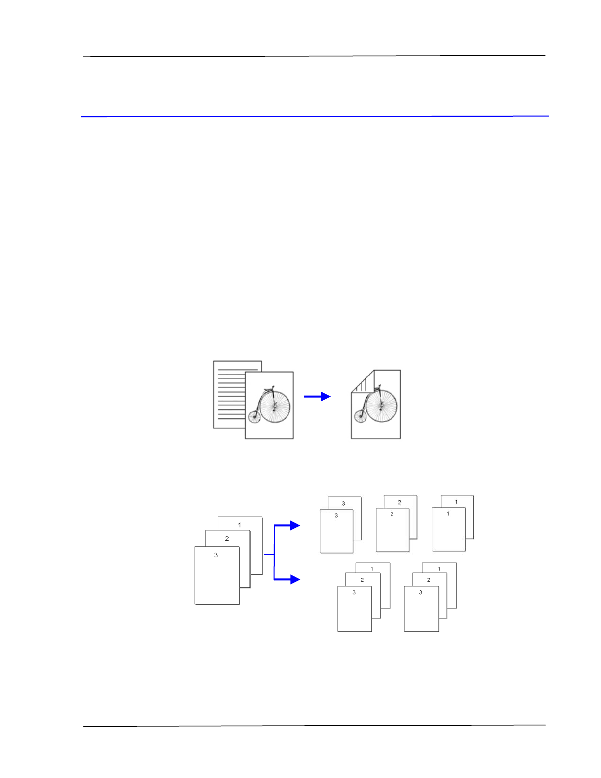
Print on Both Sides: Prints two pages (one on each side) on a single sheet
of paper.
Overview
Collate: Prints multiple copies at one time and sorts the printed pages.
1
Page 9
User’s Guide
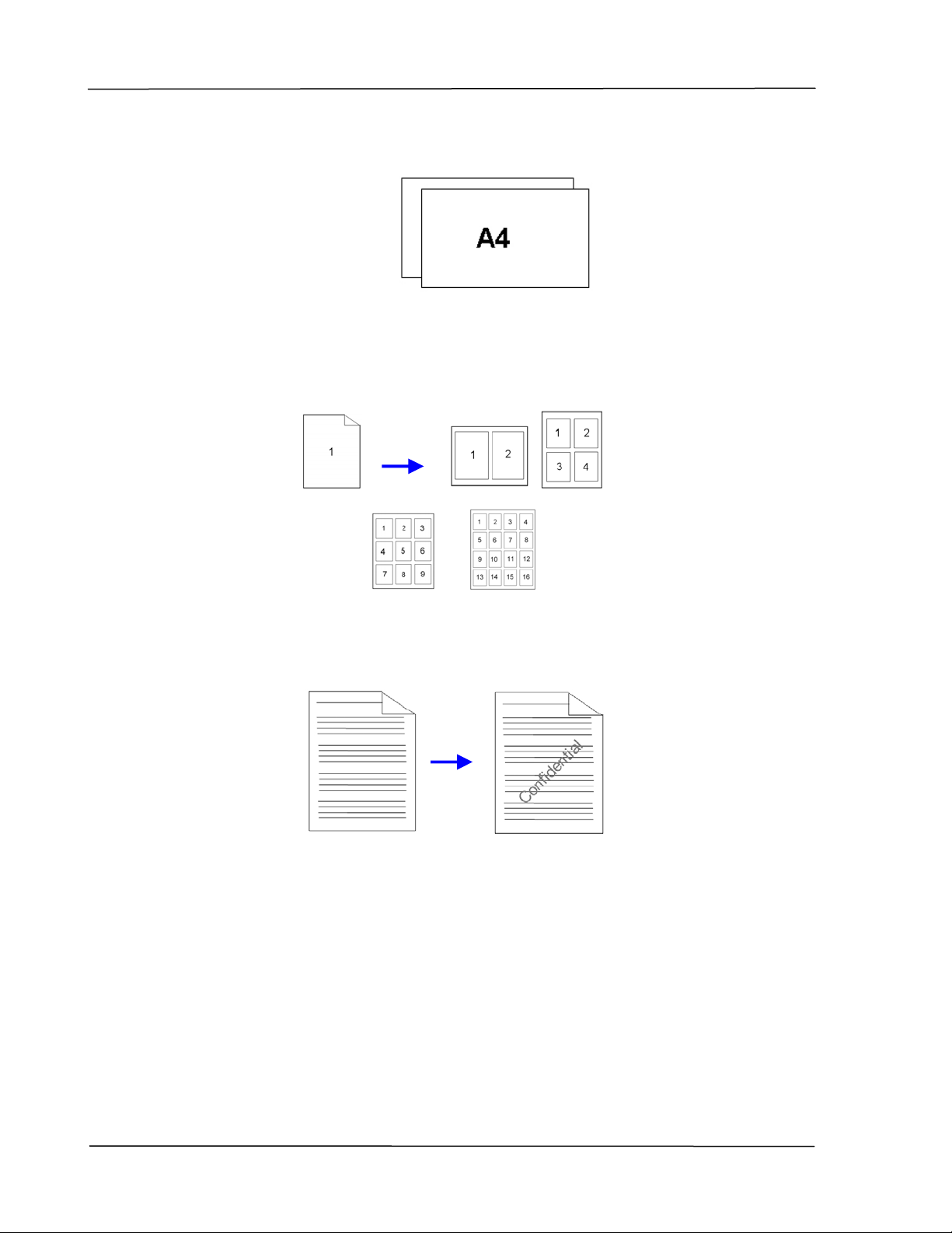
Support A4 size: The product allows you to print up to A4 size.
Print Multiple Pages on a Single Sheet: Prints two or four pages of the
original on a single sheet of paper. A maximum of 16 pages can be printed
on a single sheet of paper.
Print Watermark: Print text such as confidential, important content or
image in the background.
2
Page 10
External View
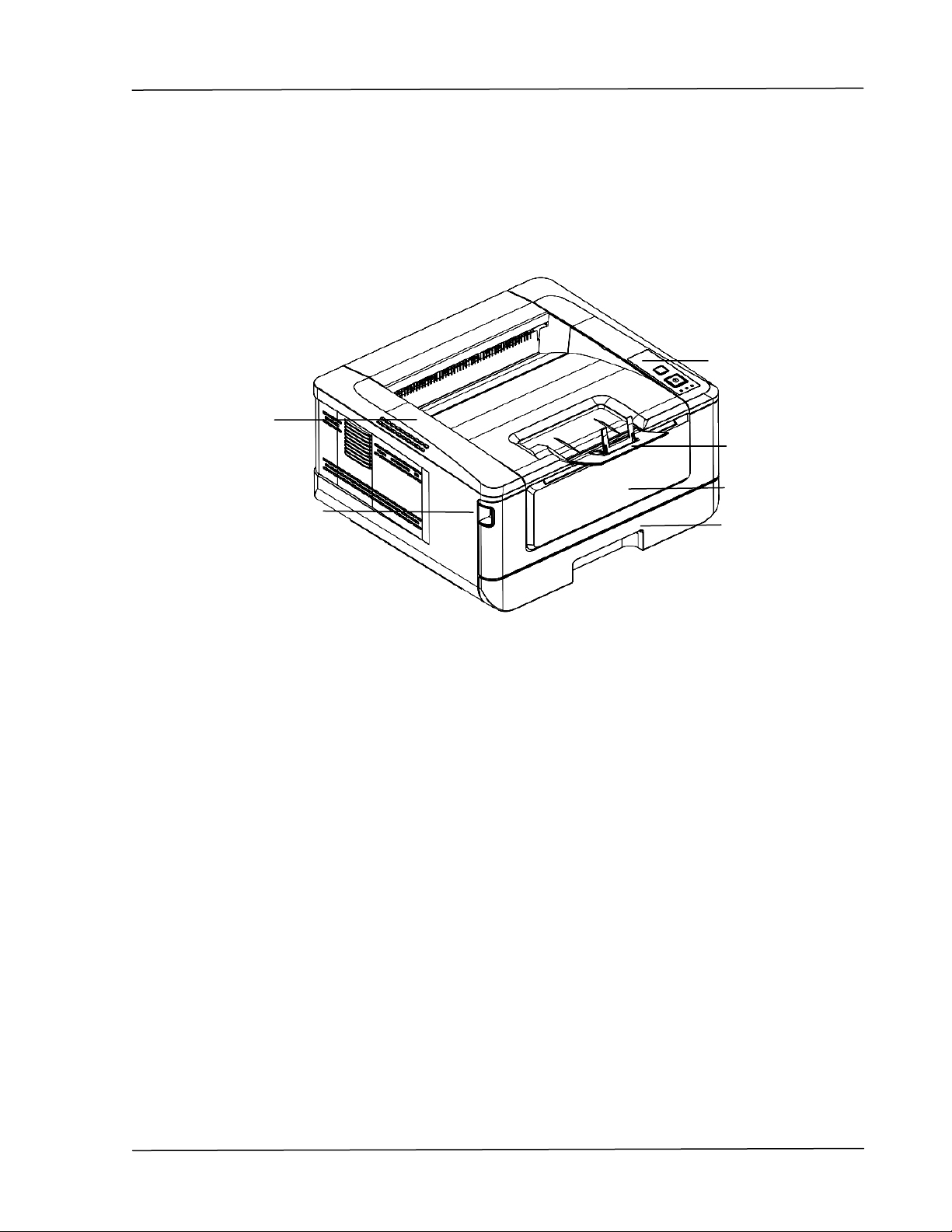
The Front View
1
2
Overview
6
5
4
3
1. Output Tray 4. Front Cover
2. Handle of the Front Cover 5. Paper Stopper
3. Main Paper Tray 6. Control Panel
3
Page 11
User’s Guide
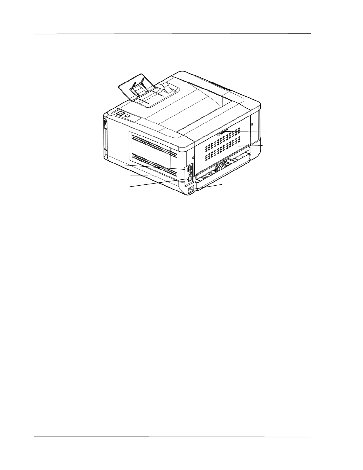
The Rear View
6
5
1
2
3
4
1. USB Port (Type A, to USB flash disk) 4. Power Receptacle
2. USB Port (Type B, to PC) 5. Rear cover
3. LAN Port 6. Handle of the Rear Cover
4
Page 12
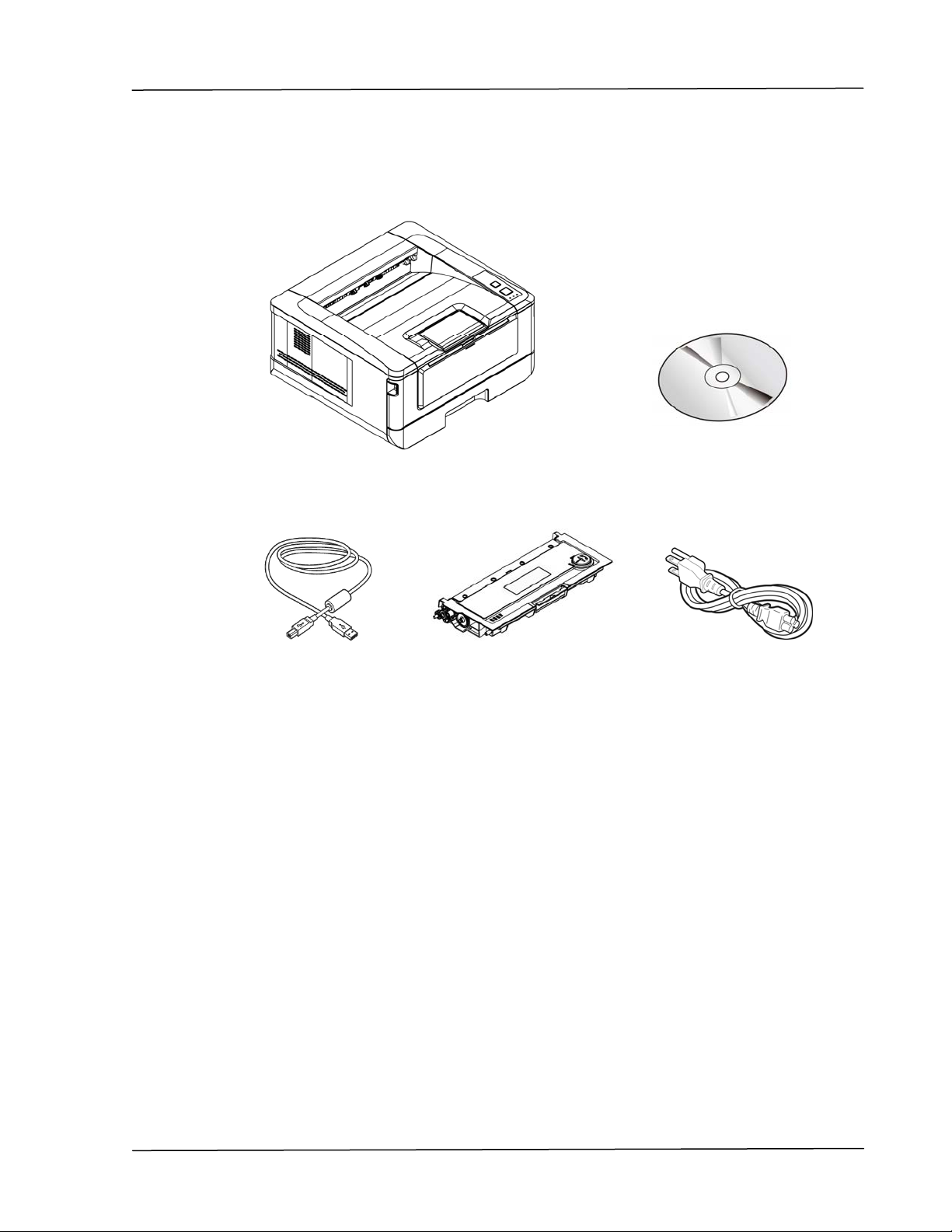
Package Contents
Main unit
Overview
Software CD (Printer Driver,
User Manual)
USB Cable
Toner Cartridge
Power Cable
5
Page 13
User’s Guide
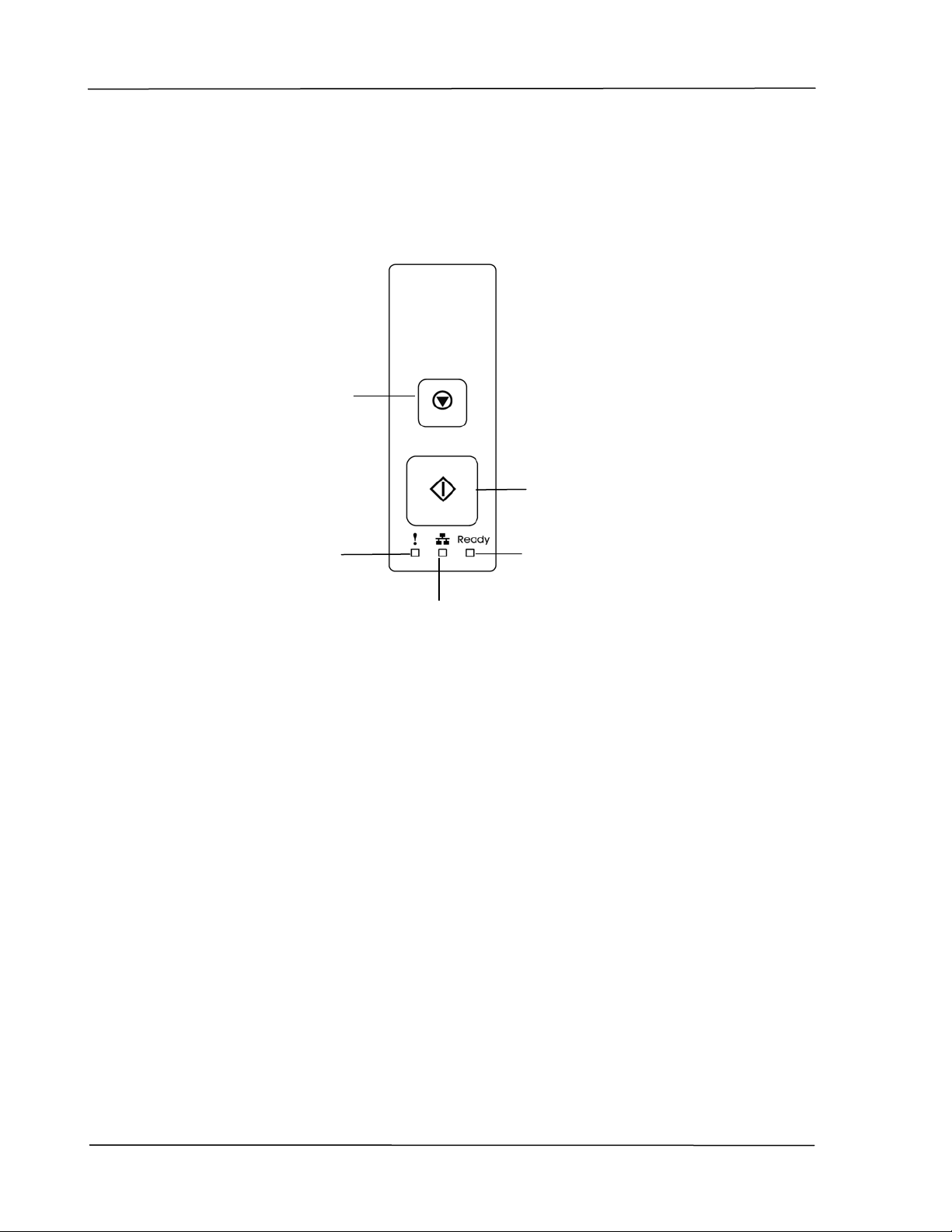
The Control Panel
Cancel Button:
Press to cancel a
Press 3 seconds to
printing job.
Print the usage
report.
Power button:
Short press to turn on the printer.
Long press to turn off the printer.
Alert LED:
Turn flashing to
indicate an error.
Power/Ready LED:
Turn solidly on when the printer is
turned on.
LAN LED:
Indicate LAN connection.
6
Page 14
Overview
Preinstallation Information
To use the product as a network device, the following network parameters have
to be collected from your network administrator. See the next section (using the
Menu to set the networking parameters) to set the network parameters.
1. DHCP Enable:
2. IP Address: . . .
3. Subnet mask: . . .
4. Gateway IP: . . .
Explanation of contents:
1. *DHCP Enable: Choose Yes to obtain IP/subnet/gateway addresses
automatically from DHCP server.
2. *IP Address: The Internet Protocol (IP) address assigned to your
machine by your network administrator or by DHCP Server.
3. Subnet Mask:
4. Gateway IP: The gateway IP address assigned by your network
Note:
1. DHCP server: With DHCP (Dynamic Host Configuration
2. IP Address: An IP (Internet Protocol) address uniquely
3. The IP address is usually written as four numbers separated by
The net mask address assigned by your network
administrator or by DHCP Server.
administrator or by DHCP Server.
Protocol), a host can automatically be given a unique IP
address each time it connects to a network--making IP address
management an easier task for network administrators. If the
DHCP server is available from your network, you do not need
to enter TCP/IP, subnet mask, gateway, and DNS information.
Instead, this information will be automatically given for the
product.
identifies a host connection to an IP network. System
administrator or network designer assigns the IP address. The
IP address consists of two parts, one identifying the network
and the one identifying your node.
periods. Each number can be zero to 255. For example,
10.1.30.186 could be an IP address.
7
Page 15
User’s Guide
2. Installation
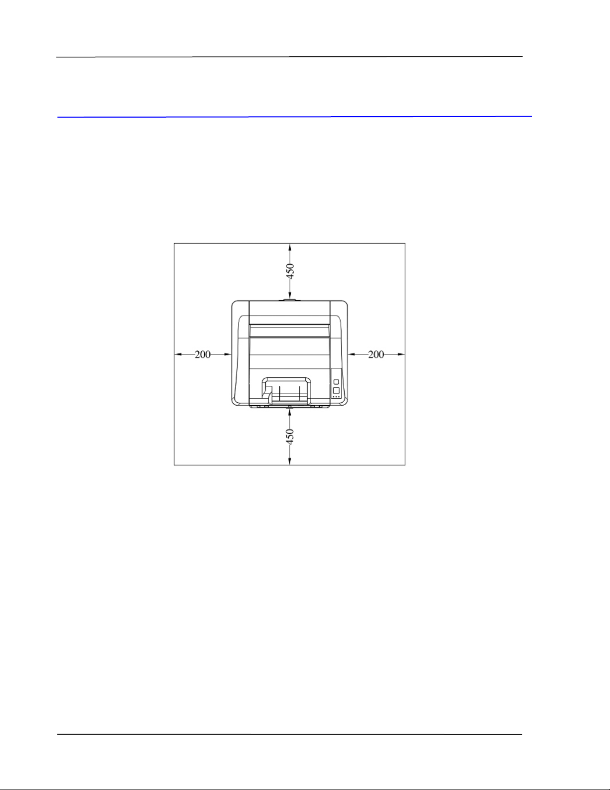
Operation Space
Please reserve the following operation space.
Measuring unit: mm
Machine dimension: 404
x 380 x 205 mm (WxDxH)
Removing the Packing Materials
Remove the packing materials, including plastic bags and tapes for product
protection.
8
Page 16
Installation
Removing the Tapes of the Toner Cartridge
Important!
When you unpack the machine, a toner cartridge has been packed
separately besides the machine. Please remove the package cushion
and tapes on the toner cartridge before using it.
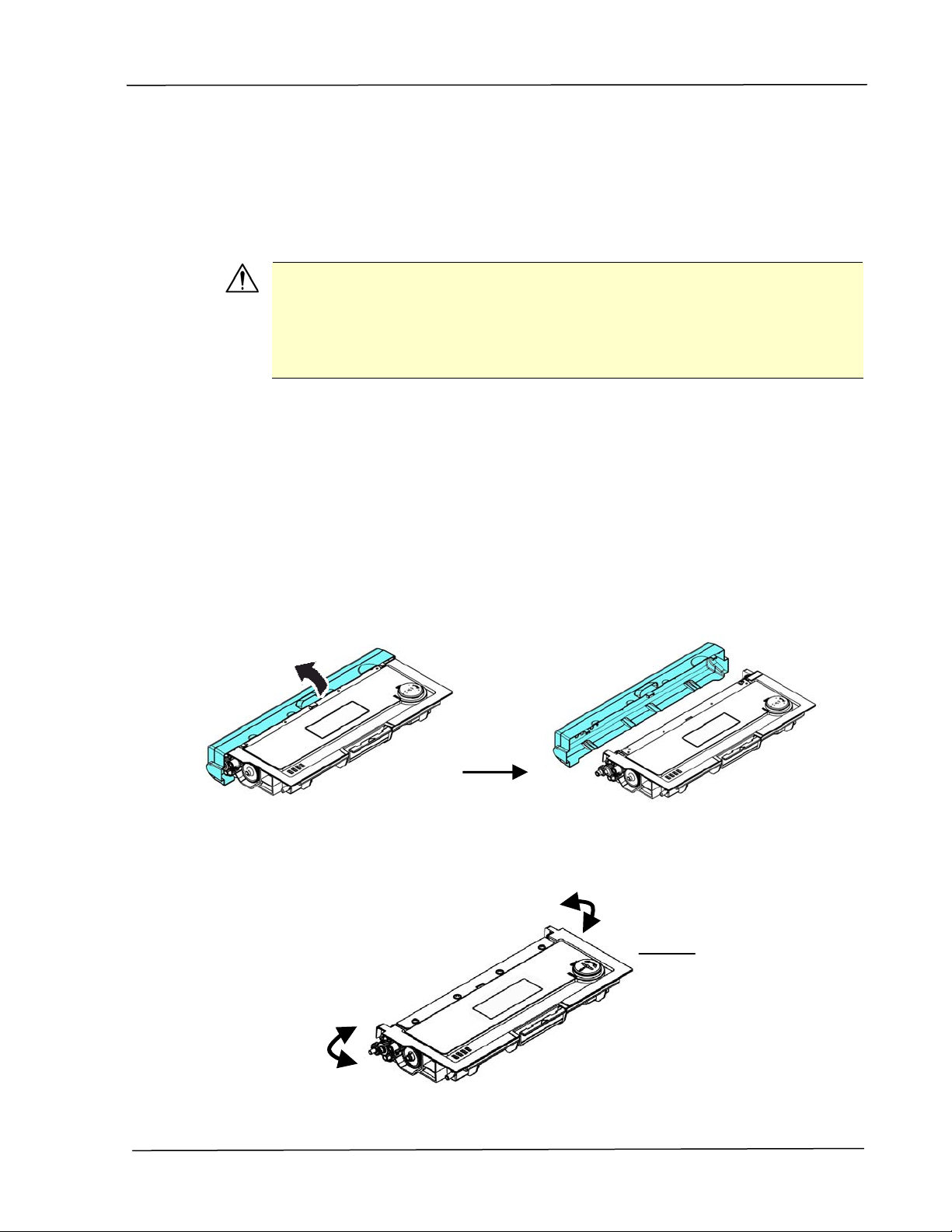
Installing the Toner Cartridge
Please follow these steps to install the toner cartridge:
1. Unpack the new toner cartridge.
2. Remove the protective cover.
3. Tilt the toner cartridge up and down and then right and left 10 times to
distribute the toner evenly inside the toner cartridge.
Toner
Cartridge
9
Page 17

User’s Guide
4. Open the front door by pulling the handles on both sides as shown.
WARNING!
Be careful not to inhale toner.
To avoid print quality problems, DO NOT touch the toner rollers.
If toner gets on your clothing or other fabric, wipe off the toner with
a dry cloth. Wash the items in cold water and dry them in the
shade.
To prevent the toner cartridge from damage, do not expose it more
than several minutes.
5. Lift the handle of the drum unit up and then pull it out as shown.
10
Page 18

Toner
Cartridge
Installation
Drum unit
4. Install the toner cartridge to the drum unit until you hear it lock into place.
5. Hold the handle of the drum and toner cartridge assembly and insert the
assembly to its original place.
6. Press down the handle of the toner cartridge to fix the toner cartridge.
6. Close the rear cover。
11
Page 19
User’s Guide
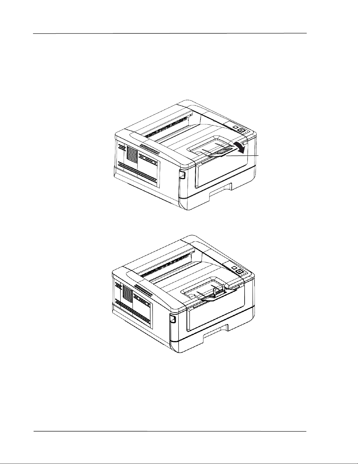
Installing the Paper Stopper
Gently lift the paper stopper and its extension to collect the paper.
Paper Stopper
12
Page 20
Loading The Main paper tray
To insert paper to the main paper tray,
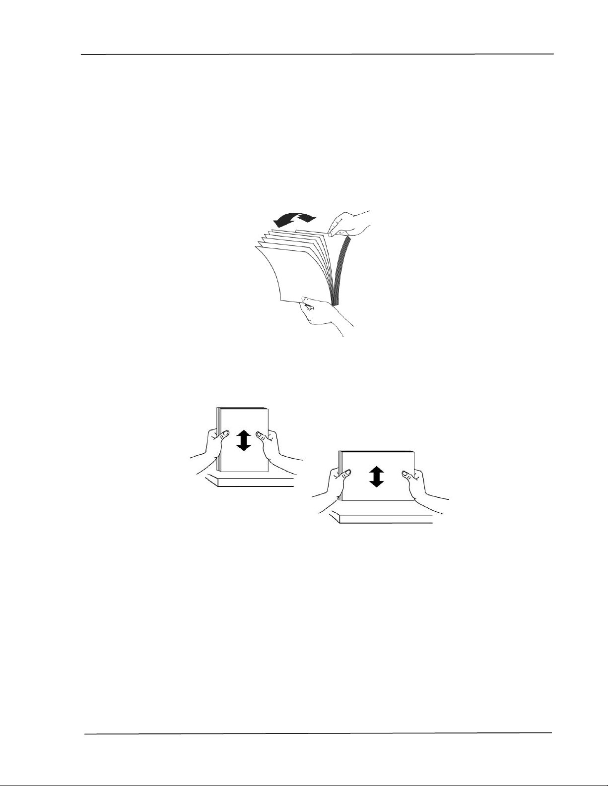
1. Fan your paper first to ensure that the pages do not stick together.
Installation
2. Align the edges of the documents by tapping the bottom of the stack against
the table top. Rotate the stack 90 degrees and repeat.
13
Page 21

User’s Guide
3. Lift the handle of the main paper tray and then pull out the main tray.
4. Push the width guide tab (), and move the width guide ()to the
correct position for the paper size being loaded.
14
Page 22

Installation
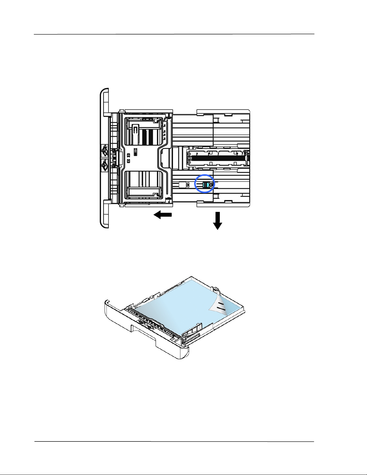
5. Push the length guide (), and slide the guide () to the correct position for
the paper size being loaded.
6. If you want to load a sheet of paper larger than the length of A4, press down
the first length adjustment latch (
tray to the right (
) until it reaches the paper size you want.
), and at the same time slide the manual
15
Page 23
User’s Guide
To move the tray back to the original A4 length, press down the second
length adjustment latch
(), and at the same time slide the manual tray
to the left (
).
7. Load the paper stack with the Printing Side Facing Down as illustrated.
16
Page 24

8. Insert the tray to the printer.
Paper sizes and weights used for Main paper tray
Installation
Paper capacity
Paper size A4 (210 x 297 mm)
Custom Size: 76.2 x 127 mm ~ 216 x 356 mm
Paper weight 16 ~ 28 lbs (60 ~ 105 g/m²)
* Duplex printing is available only for paper in A4, B5 or Letter size.
250 pages(70 g/m² plain paper)
A6 (105 x 148 mm)
A5 (148 x 210 mm)
B6 (125 x 176 mm)
B5 (176 x 250 mm)
Letter (216 x 279 mm)
Legal (216 x 356 mm)
(3 x 5 in. ~ 8.5 x 14 in.)
17
Page 25

User’s Guide
Note:
To ensure the best quality printing and copying, please use the paper or
media which we have recommended.
Make sure to fan your paper before loading it to the paper tray.
If there are instructions about the printing side on the package of your
paper, please follow the instructions to load your paper properly with
the correct printing side to the paper tray.
If the printing quality is not satisfactory or paper jams are easily to
occur, turn over the paper stack so that the top page is now on bottom
and then reload it to the paper tray.
Pack and seal the remaining paper with the original packaging and store
the paper in a dark and dry location away from the sunshine. Paper
which collects much moisture is easy to cause jam during printing.
Important:
To avoid the chance of miss-fed, make sure the length guide tab and
length slider are installed in their proper positions.
Make sure the end of your paper slightly touch the length guide as
indicated in below.
Make sure the length
slider is installed in the specified location in either
position A or B as shown in below.
Position A Position B
Length
Guide Tab
Length
Guide Tab
18
Page 26
Installation
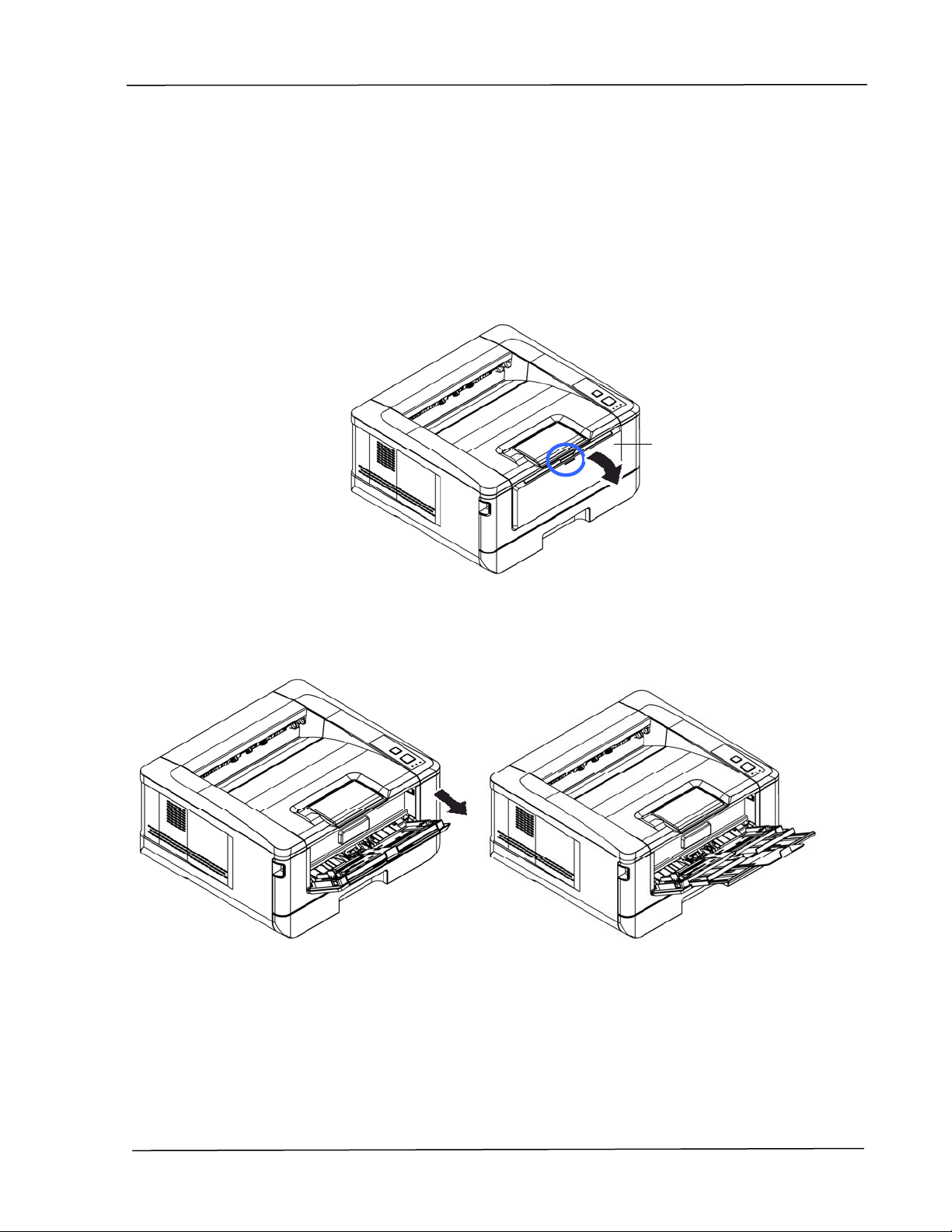
Loading the Manual Tray
To insert paper to the manual tray,
1. Hold the handle of the manual tray, and pull it down to open the manual tray.
Manual Tray
2. Pull out the tray extension to fit your desired paper length.
19
Page 27
User’s Guide
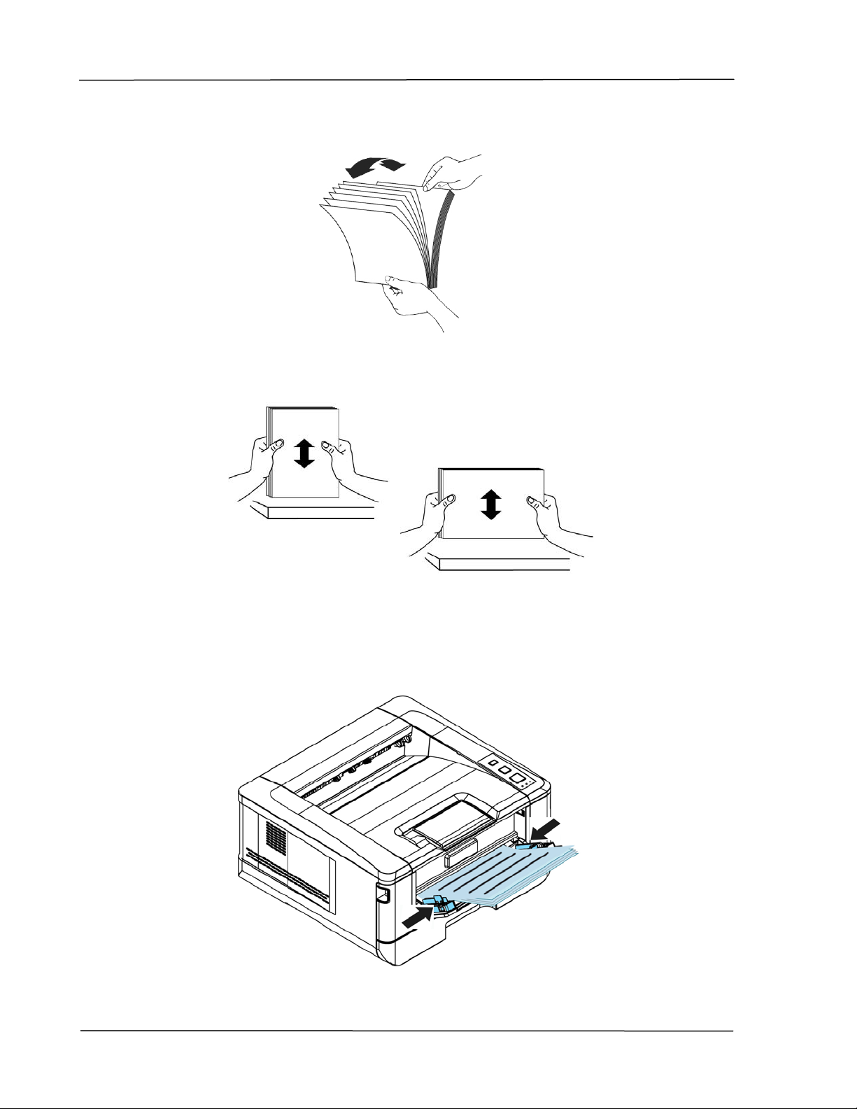
3. Fan your paper first to ensure that the pages do not stick together.
4. Align the edges of the documents by tapping the bottom of the stack against
the table top. Rotate the stack 90 degrees and repeat.
5. Load the paper stack with the print side Facing UP as illusrated.
6. Slide the paper guides so that they lightly touch the paper stack.
20
Page 28

Paper size and weights used for Manual T ray
Installation
Paper capacity
Paper size
10 pages(70 g/m² plain paper)
A4 (210 x 297 mm)
A6 (105 x 148 mm)
A5 (148 x 210 mm)
B6 (125 x 176 mm)
B5 (176 x 250 mm)
Letter (216 x 279 mm)
Legal (216 x 356 mm)
Custom Size: 76.2 x 127 mm ~ 216 x 356 mm
(3 x 5 in. ~ 8.5 x 14 in.)
Paper weight 16 ~ 43 lbs (60 ~ 163 g/m²)
* Duplex printing is available only for paper in A4, B5, or Letter size.
Note:
To ensure the best quality printing and copying, please use the paper or
media which we have recommended.
Make sure to fan your paper before loading it to the paper tray.
If there are instructions about the printing side on the package of your
paper, please follow the instructions to load your paper properly with
the correct printing side to the paper tray.
If the printing quality is not satisfactory or paper jams are easily to
occur, turn over the paper stack so that the top page is now on bottom
and then reload it to the paper tray.
Pack and seal the remaining paper with the original packaging and store
the paper in a dark and dry location away from the sunshine. Paper
which collects much moisture is easy to cause jam during printing.
21
Page 29
User’s Guide
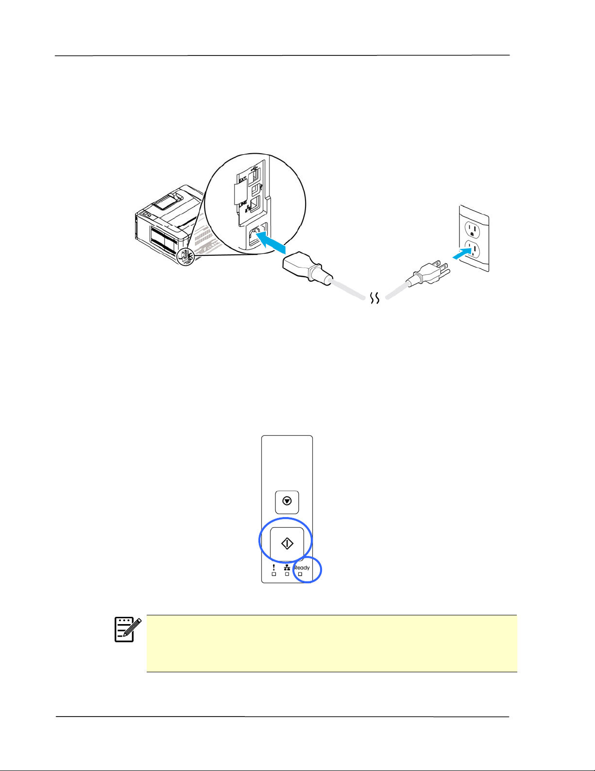
Connecting to Power
1. Connect the of the power cable to the power jack of your product.
2. Connect the other end to an appropriate power outlet.
Turning On The Printer
To turn on the printer, press the power button located on the control panel.
Ready LED will be lit.
Note:
When the product is not in use, please long press the power button until
the Ready LED is turned off to get a zero power consumption state.
22
Page 30
Installation
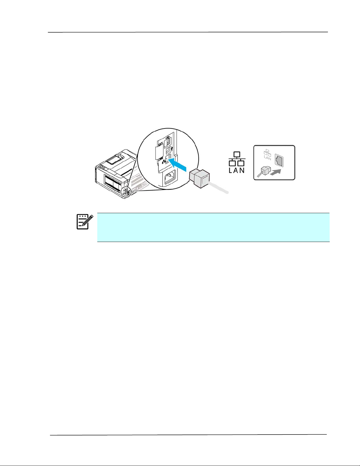
Connecting to the Network
Connect the printer to the network to use the network printing function.
1. Connect one end of your network cable to an available port of your Ethernet
.
Hub
2. Connect the other end to the LAN port at the back of the product as shown.
Note:
To obtain the IP address, press and hold the Cancel button for 3 seconds. A
usage report containing the IP information will be printing.
23
Page 31
User’s Guide
Installing the Printer Driver (Windows)
System Requirement
Windows XP, Windows Server 2003, Windows Vista, Windows 7 ~ 10
For USB Interface Users
Please follow these steps to install the printer driver if this machine is connected
to your computer via a USB cable.
1. Insert the supplied CD into your CD-ROM drive. The installation menu appears,
2. Click “Install Printer Driver” and follow the on-screen instructions to install
3. When the Setup Type dialog box appears, select USB.
Important!
DO NOT connect the USB cable before installing the printer’s
driver.
as shown below.
the program.
4. During installation, the USB Connection dialog box will be prompted to instruct
you to connect the machine to your computer with a USB cable.
a. Connect one end of the USB cable to your computer.
b. Connect the other end to the USB port of your product.
24
Page 32

Installation
5. When the “Found New Hardware” screen appears, click Next and follow the
on-screen instruction to complete the installation.
6. When the Finish dialog box appears, click Finish to complete.
If you have successfully installed the printer’s driver, you will find a printer
“AP30XX” has been added in the “Printers and Faxes” option from the Control
Panel.
25
Page 33

User’s Guide
Uninstalling the Printer Driver
1. Make sure your USB cable is connected to your product.
2. From the “Start” menu, select “All Programs”, the product model, and then
For Network Interface Users
Please follow these steps to install the scanner, printer, and fax drivers if this
machine is connected to your computer via a network.
1. Insert the supplied CD into your CD-ROM drive. The in stallation menu wil
2. To install the scanner driver and printer driver:
“uninstall Driver”.
be displayed.
Click 「Install Scanner Driver and Printer Driver」and follow the
on-screen instructions to complete the installat ion of the program.
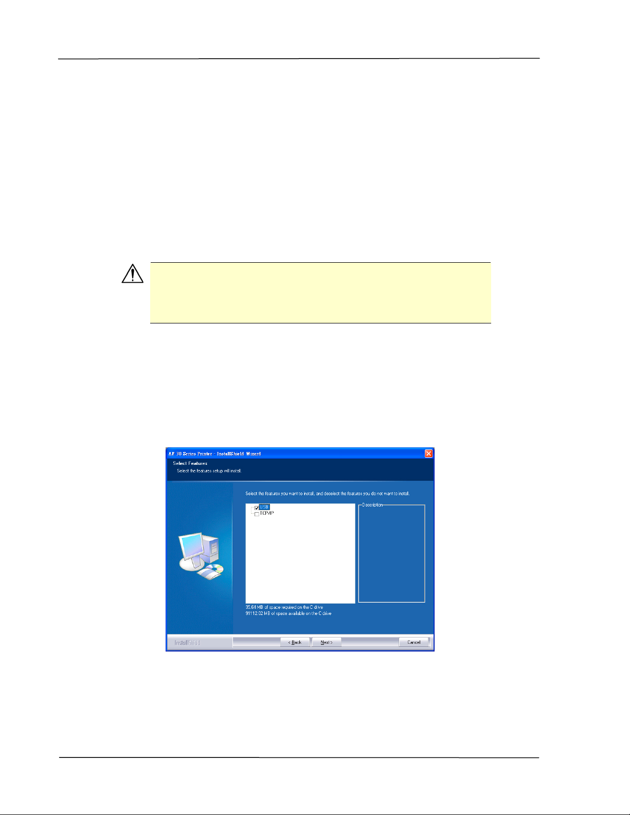
3. When the Setup Type dialog box appears, check [TCP/IP] and click
[Next] to continue. If you need to connect the product to a wireless
network, check [USB] since the Network Setup Tool is included in the USB
driver and only available when the product is connecting to your computer
through the USB cable.
4. When the following Set IP dialog box appears, choose one of the following
options and click [>] to add to the printer list. When the desired option
setting is completed, click [OK]. (Follow the preceding section –
Checking the Product’s Default IP Address to obtain the product’s default
IP address.
26
Page 34
Installation
10.1.23.91
Enter the product’s host name to be connected in
Host Name
the blank box of the Host Name option.
To add more host names if more than one AP30
Series are connected in the network, click 「More」
next to the Host Name box.
IP Address Enter the product’s IP address to be connected in
the blank box of the IP Address option.
Searches the product’s printers automatically, and
Automatic Search
all the product’s host names found in the network
will be displayed in the box of the Automatic Search.
Use your mouse to choose your desired host name
to be connected.
5. During installation, the [USB Connection] dialog box will be prompted to
instruct you to turn on the PRINTER and then connect the PRINTER to
your computer with a USB cable.
6. When the Finish dialog box appears, choose 「Finish」to complete.
If you have successfully installed the printer’s driver, you will find a
printer, 「AP30 Series NetWork」, has been added in the 「Printers and
Faxes」option from the Control Panel.
27
Page 35

User’s Guide
Changing the Product ’s IP Address in a Wired Network
To change the product’s IP address, you need to install the Network Setup Tool.
The Network Setup Tool is included in the USB printer driver. After the
installation of the USB printer driver is completed, the Network Setup Tool is
automatically installed onto your computer. Follow these steps to update the IP
address to the product in a wired network.
You may also define your network connection via the web page. (See more details
in the subsequent section Customize System’s Settings via the Embedded Web
Page in Chapter 5.
1. Make sure the product is connected to your computer via a USB cable.
2. Start Network Setup Tool by choosing the Start button and then select
All Programs>AP30XX PRINTER>Network Setup Tool in succession.
The following Network Setup Tool screen will be prompted.
AP30 Series Printer
3. On the [General] page, check [Wired (Ethernet)] Network.
4. Click the [Wired (Ethernet)] tab to prompt the Wired (Ethernet) page.
28
Page 36

Installation
5. Check [Obtain an IP address automatically] to obtain the IP address
directly from the DHCP server or you may enter your static IP on the [IP
Address], [Subnet Mask], and [Gateway] field respectively.
6. If you have assigned a specific IP, enter your domain name server and
WINS server as well and then click [Update Setting] to update the IP
information to the product.
7. If update is successfully, an [Update Device Successfully] message will
be displayed and the Network Setup Tool will be automatically closed.
29
Page 37

User’s Guide
Setting the Product’s IP Address in a Wireless Network
To set an IP address to the product, you need to install the Network Setup Tool.
The Network Setup Tool is included in the USB printer driver. After the
installation of the USB printer driver is completed, the Network Setup Tool is
automatically installed onto your computer. Follow these steps to set and update
the IP address to the product in a wireless network:
You may also define your network connection via the web page. (See more details
in the subsequent section Customize System’s Settings via the Embedded Web
Page in Chapter 5.
To wirelessly connect the product to a network, you need to install a Wi- Fi dongle
to the product at the back of the USB port.
USB port
1. Make sure the product is connected to your computer via a USB cable.
2. Start the Network Setup Tool by choosing the Start button and then
select All Programs>AP30XX Printer>Network Setup Tool in
succession. The following Network Setup Tool screen will be prompted.
AP30 Series Printer
30
Page 38
Installation
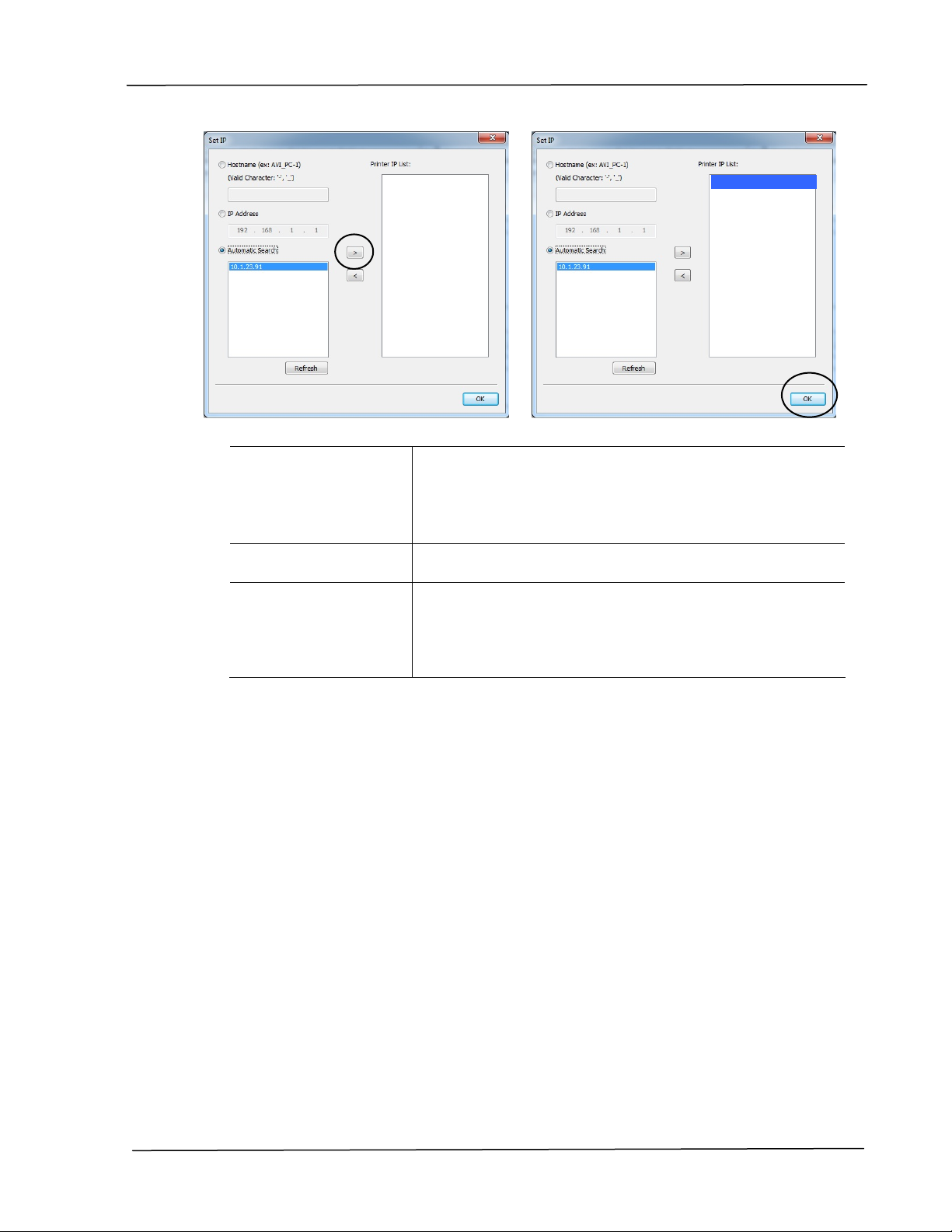
3. On the [General] page, check [Wi-Fi (Station)].
4. Click the [Wi-Fi (Station)] tab to prompt the [Wi-Fi (Station)] page.
5. Check [O bt ain an IP address automatic ally ] to obtain the IP address
directly from the DHCP server or you may enter your static IP on the [IP
Address], [Subnet Mask], and [Gateway] field respectively.
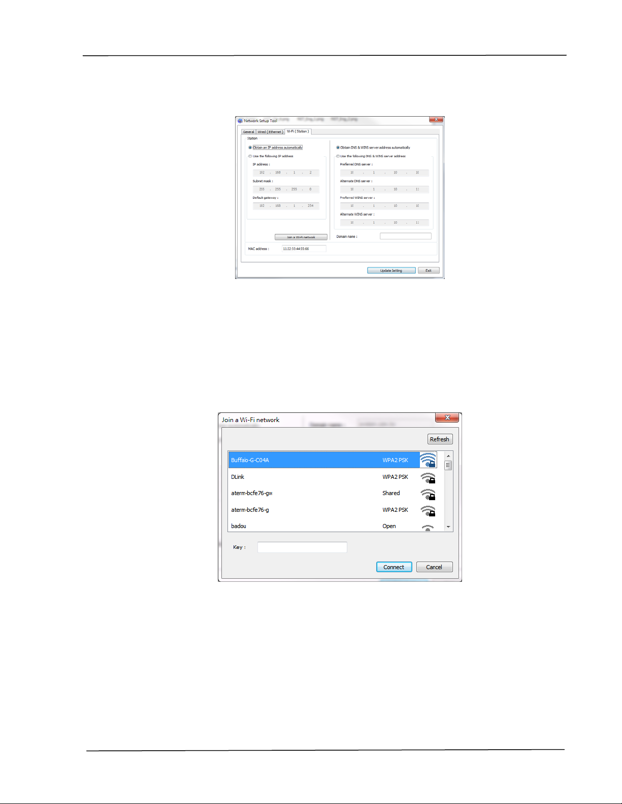
6. Click [Join a Wi-Fi network] and the currently connected wireless
networks will be displayed. Select the wireless network you want to
connect and then enter the security key if required.
7. Click [Connect] to start connecting the SSID (wireless network name) and
then update the IP information to the product.
8. If update is successfully, an [Update Device Successfully] message will
be displayed and the Network Setup Tool will be automatically closed.
31
Page 39

User’s Guide
Uninstalling the Scanner Driver and Printer Driver
1. From the 「Start」menu, select 「All Programs」, 「the AP30 Series
2. Follow the instructions on the screen to complete removing the scanner
Printer」, and then 「Uninstall Driver」.
Or from the 「Start」menu, select 「Control Panel」, 「Add or Remove
Programs」, 「the AP30 Series Printer」, and then 「Remove」.
driver and the printer driver.
32
Page 40

Installation
Installing the Printer Driver (Mac OS)
System Requirement
Operating System:
Mac OS X 10.11 or later
Computer:
Recommended: Intel
Minimum: Intel
PowerPC G5 1.6 GHz
Memory:
Recommended: 1 GB or more
Minimum: 512 MB
®
®
CoreTM Duo Processor 2.4 GHz or higher
CoreTM Duo Processor 1.83 GHz
Turning on the Printer
Press the Power button on the front panel, the Power LED will f lash. When it is
finished and ready to scan, the LED indicator will stop flashing and become
steadily on. To turn off the scanner, press the Power button for about 3
seconds, the Power LED will be off.
Installing the Printer Driver
NOTE: The screens in this section are basically from Mac OS 10.11. The screens on
your Macintosh will vary depending on your operating system.
Follow the procedure to install Avision’s AP30 Series printer driver for Macintosh
computer from the CD-ROM supplied with the printer.
1. Turn your computer on, and log in with an account that has admin rights.
2. Insert the Software CD-ROM into the CD-ROM drive. The printer program -
Avision AP30…pkg will be displayed.
33
Page 41

User’s Guide
3. Double-click the [Avision AP30…] icon.
4. Click the [Continue] button on the Welcome window.
5. If you wish to change the default installation disk, click [Change Install
Location…] or click the [Install] button to continue installing the program.
6. Log in with a password that has admin rights and click the [Install Software]
button.
7. The computer begins installing the software.
34
Page 42
Installation
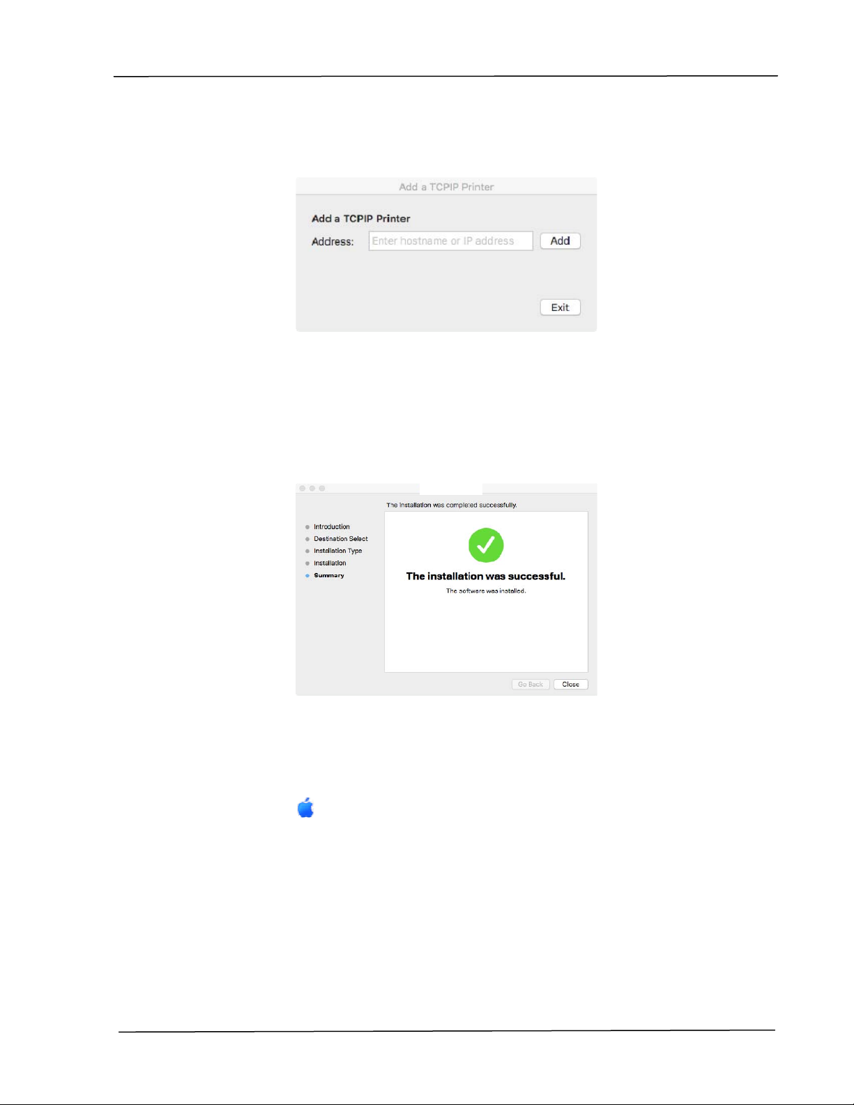
8. When the following screen is prompted, enter the IP address of the printer
and click [Add]. *If you wish to connect the printer to your computer with a
USB cable, skip the IP address and click [Exit] to continue.
9. When [Add Printer AP30_Net Successful] message is displayed, click [Exit]
to continue. (If wish to add more AP30 printer, enter the IP address again and
then click [Add] to continue.)
10. When the [The installation was successful] screen appears, click the
[Close] button to close the installation.
11. Remove the Setup CD-ROM from the CD-ROM drive. *If you wish to connect
the printer to your computer with a USB cable, connect the printer with the
USB cable now. If you already did, unplug and replug the USB connector
again.
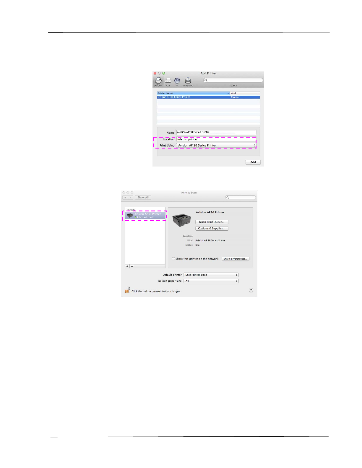
12. Select the
Apple icon in the top-left corner, then click [System
Preferences] and then [Print & Scan].
35
Page 43

User’s Guide
13. You can find an AP30 printer has been added in your printer list.
Or click [System Preferences] icon on your dock, and then [Print &
Scan].
36
Page 44

Adding a new Printer
To add a new printer, follow these steps:
Installation
1. Select the
Preferences] and then [Print & Scan].
Or click [System Preferences] icon on your dock, and then [Print &
Scan].
2. Click
Apple icon in the top-left corner, then click [System
and then [Add Other Printer or Scanner] to add the printer.
3. A dialog appears listing printers on your local network. It may take a minute
or two for your printer to appear. Select your printer when it appears in the
list.
37
Page 45

User’s Guide
If your printer still doesn’t appear in the list, try adding the printer by its IP
address. While entering the IP address by clicking the IP icon, be sure to
include the address with [:9101], for example, 192.168.1.100:9101.
4. Locate the printer driver by clicking the arrow button of the [Print Using]
option and then select [Select Printer Software].
38
Page 46
Installation
5. A dialog appears listing current printer drivers installed on your computer.
Select your printer and click [OK]. Your [Print Using] option will display the
printer you have selected.
6. Click the [Add] button to add the printer. Now your printer will be in the list
on the upper-left corner as shown in below.
7. Close the [Print & Scan] window.
39
Page 47
User’s Guide
Using the Optional Scan Module (CSA6) for ID Cards
Simply loading your ID card to the scan module (CSA6), the copy can be started
and in a second the front side and rear side of your ID card are printed in one side
of a sheet.
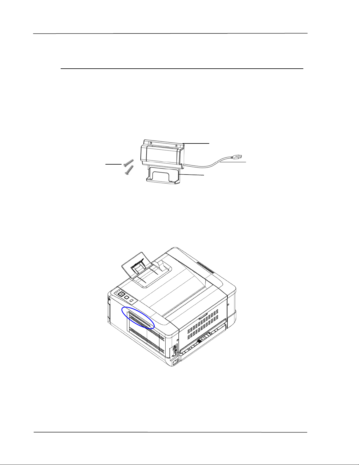
Knowing the Scan Module:
Card Feeder
Fixing
Screws x 2
Removing the Mylar:
Locate the mylar for the reserved holes on side cover as shown and remove it with
a box cutter.
Output Tray
USB Cable
40
Page 48

Installation
Installing the Scan Module:
1. Note two reserved holes on the side wall beneath the operational panel and
fasten the scanning module with two fixing screws as shown.
2. Connect the USB cable to the USB port on rear side.
Fixing
Screws
USB Port
USB Cable
41
Page 49
User’s Guide
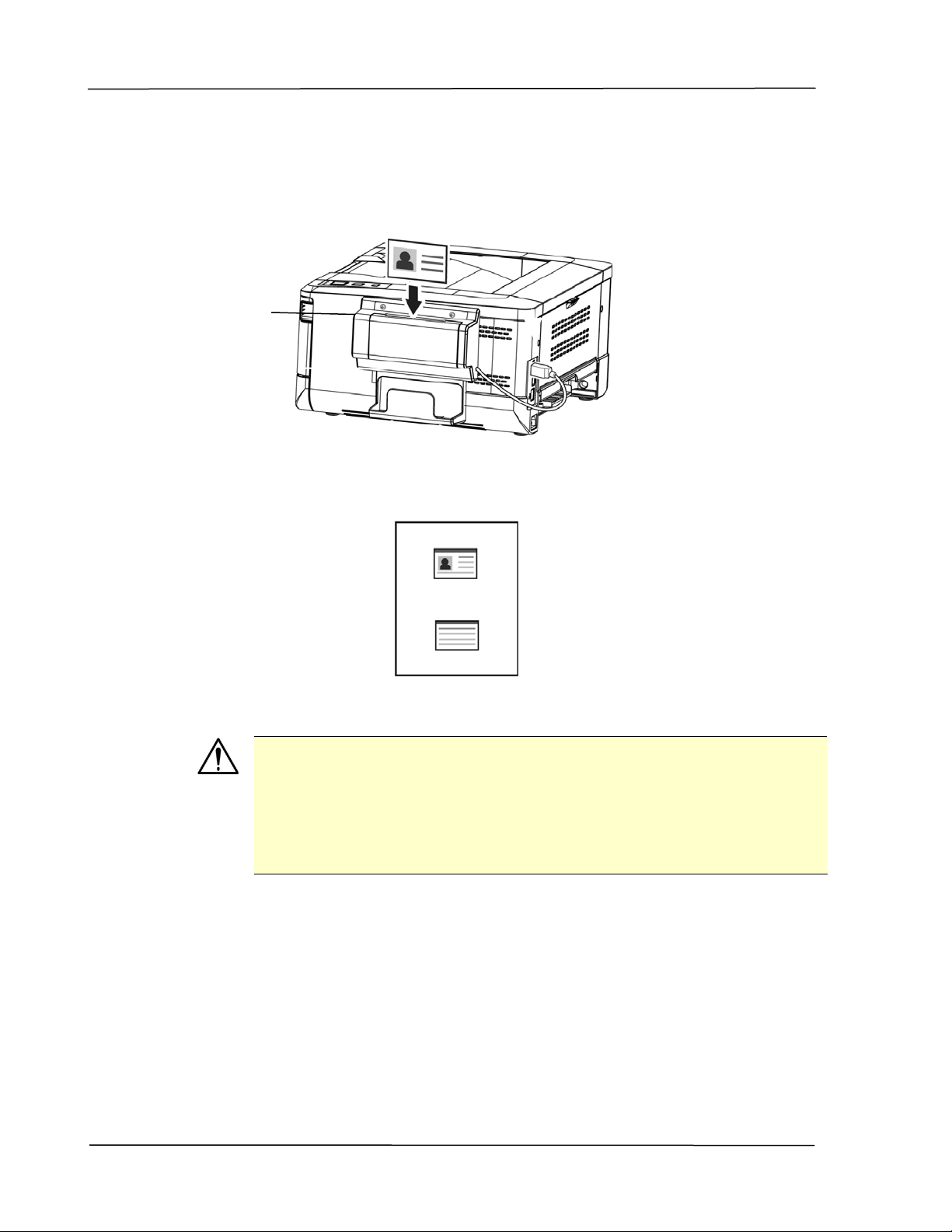
Making ID Card Copy:
1. Insert your card FACE OUTWARD to the card feeder and make sure the
2. In a second, the front side and the rear side of your ID card will be copied in
bottom of card feeding first as illustrated.
Card
Feeder
one side of a sheet.
Note:
Only one card can be inserted at one time. The scan module does
not allow to be fed more than one card at a time.
To change the default settings of the optional scan module
(CSA6) for ID card, please go to the product’s embedded web
page as described on page 36.
42
Page 50

3. Customizing the Product’s Settings
This chapter is specifically targeted to the persons who are responsible for the
administration of the product. It is recommended that the administrator read this
chapter before installing the machine.
The product’s settings can be customized via the product’s embedded web page.
How to customize the product’s settings via these two met hods will be described
in the following sections.
Note:
When installing the product for the first time, it is recommended
that the Administrator retain the default system settings. The
settings can be customized at a later date once you are familiar
with the operation and functionality.
Page 51
User’s Guide
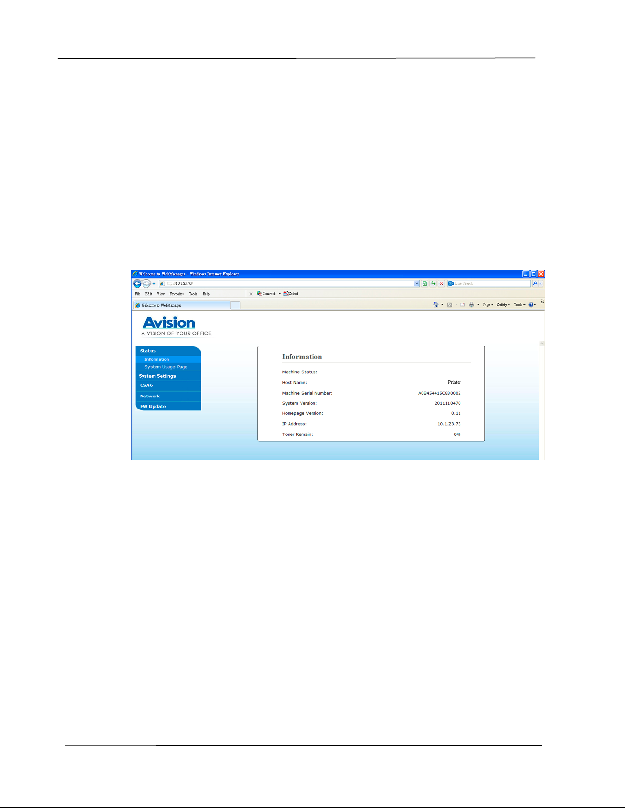
Customize System’s Settings via the Embedded Web Page
Note: Any update of the web page requires administrator’s login.
You may also define your Wi-Fi connection type via the web page.
1. Refer to the preceding section to setup the product’s network settings.
2. Open your browser and type the product’s IP address on the URL address ,
for example, http://10.1.23.73 and press Enter
web page will be displayed
.
. In a second, the embedded
Enter your desired setting on your selected items.
3.
44
 Loading...