

Page 1
Network Power Splitter SP125
Network Power Splitter SP-125 Quick Installation
0. Before Getting Started
Before getting started, please check Network Power Splitter SP-125 package contents is integrated ,
router/switcher or PSE meet with the 802.3af. and power consumer is 5V/2A(max) or 12V/1A(max)
Note: USB connect is used to 5V DC power supply only, not for data transmission
With problems, please refer to User Manual from the provided CD for details.
Package Contents:
Your package ships with the following items:
Network Power Splitter SP125
Terminal Block to 12V (1A) PowerJack Cable x 1pc.
USB to DC convert cable x 2 pcs.
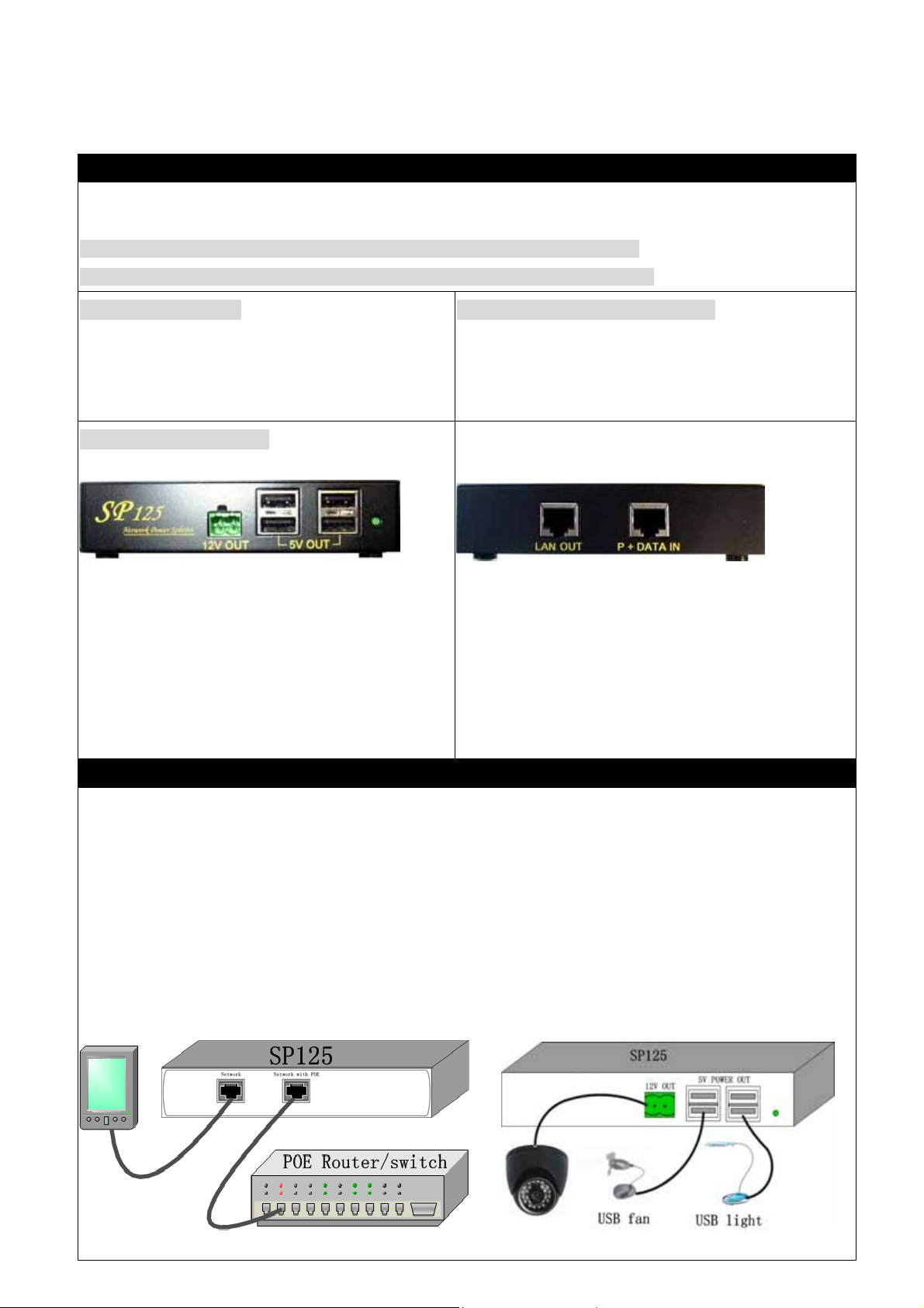
Interface Introduction:
Front Panel :
Ports:(From left to right ) :
* 12V out (1 Amp) : for IP Kamera or other power.
* USB port : User can use the 4 pcs UDB power supply
for users USB device.
* Total Power wattage: 12 Watts
* Power LED light: the green light will be on when
power is received through RJ-45 jack from POE router
Minimum System Requirements
POE Router ( PSE - Power supply )
Back Panel
Ports (Left to Right):
* Lan Out: Normal network jack - no power input passed
through in this port, only output
* P+Data In : Receive power and data from POE router by
normal RJ-45 cable jack.
Hard ware Installation
1. To get power from POE router, please connect RJ45 cable (not crossed cable) f rom POE router output to the
SP=125 port “ P+Data In “
2. When connected there will be power & network signals. The USB ports, 12V Terminal Block port and
Network (RJ45 Out) port on SP-125 will begin transmitting information and or power:
* In front panel:
User can connect “LAN OUT” to IP Camera / HUB / Router through RJ-45 jack to access network information.
* In back panel:
- Connect “12V out “ by
- Connect “5V Power out “ by USB jack to connect devices (Such as USB FAN, USB Speaker and etc.)
Terminal Block to 12V (1A) Power Jack Cable to get 12V / 1A power
Page 2
Network Power Splitter SP125
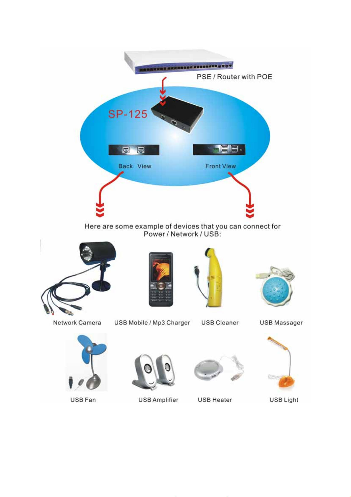
Illustration :
 Loading...