

Page 1
Ref#92550806002
IP Power 9255Pro
User Manual
Release Date: 11/06/2012
Manual Version: 1.1
Firmware: Ver. 4.03
- 1-
Page 2

Ref#92550806002
Warning: Any changes made to this equipment without permission may cause
damages to the device!
IMPORTANT NOTICE
1. IP Power 9255Pro was designed to be used with a protective covering, the
user is responsible for any damages caused from misuse, use under
inappropriate conditions or from wrong power adaptor.
2. Please use the power adapter provided by the dealer, the manufactur er is not
responsible for any damage caused from using power adapters not.
3. Do not shake the IP Power 9255Pro in any fashio n
4. Please contact the dealer If IP Power 9255Pro is not working properly.
Copyright © 2012 All rights reserved. No part of this publication may be
reproduced, stored in a retrieval system, or transmitted in any form or by any
means, electronic, mechanical, photocopying, recording or otherwise, without the
prior written consent of us.
All trademarks and products mentioned in this document are the properties of us.
- 2-
Page 3

Ref#92550806002
Table of Contents
1.) WELCOME .........................................................................................................................5
NTRODUCTION ..........................................................................................................................5
I
M
INIMUM SYSTEM REQUIREMENTS ...............................................................................................6
2.) PRODUCT OVERVIEW ........................................................................................................7
EATURES .................................................................................................................................7
F
S
PECIFICATION ..........................................................................................................................7
P
ACKAGE CONTENTS ...................................................................................................................8
3.) INTERFACE DESCRIPTION ...................................................................................................9
ARDWARE INTERFACE ................................................................................................................9
H
4.) SETTING UP YOUR DEVICE ............................................................................................... 10
EFORE WE START .................................................................................................................... 10
B
S
ETUP FOR INTERNET ACCESS ...................................................................................................... 10
9255P
RO QUICK INSTALLATION .................................................................................................. 11
U
SING IP EDIT ......................................................................................................................... 12
U
SING IP SERVICE .................................................................................................................... 14
5.) WEB INTERFACE .............................................................................................................. 16
OWER CONTROLS ................................................................................................................... 17
P
P
OWER CONTROL ............................................................................................................................... 17
URRENT VALUE, SETTING , CONSUME CHARE & TEMPERATURE VALUE ...................................................... 18
C
S
CHEDULER ............................................................................................................................. 20
P
ING SETTINGS ........................................................................................................................ 21
S
ETUP ................................................................................................................................... 23
S
YSTEM ............................................................................................................................................ 24
DDNS .............................................................................................................................................. 25
E-
MAIL ............................................................................................................................................. 27
C
HANGE PASSWORD ........................................................................................................................... 28
W
AKE ON LAN ................................................................................................................................... 28
SERVER CONFIGURATION ................................................................................................................. 29
IP
T
IME ................................................................................................................................................ 29
L
OGOUT ................................................................................................................................. 30
6.) CONTROLLING THE DEVICE .............................................................................................. 30
- 3-
Page 4

Ref#92550806002
CGI HTTP COMMANDS ............................................................................................................. 30
A.) SET POWER COMMAND ................................................................................................................. 30
B.) POWER DELAY .............................................................................................................................. 31
C.) READ POWER COMMAND ............................................................................................................... 31
D.) READ CURRENT & TEMPERATURE COMMAND ................................................................................... 32
ELNET COMMANDS ................................................................................................................. 32
T
7.) FREQUENTLY ASKED QUESTIONS (F.A.Q) .......................................................................... 35
- 4-
Page 5

Ref#92550806002
1.) Welcome
Introduction
The 9255Pro is an industrial grade single port relay perfect to power
management throug h an Ethernet connection. This device can easily integrate
with other devices and allow power control with your integrated system.
In the tiny device, user can Detect consume current and control their pocket
and child can touch the plug safely as there is Power leakage protection plug
design With zero cross circui t desi gn make 9255Pro the most friendly IP Power
for family application in the world . With leakage protection design in 9255Pro,
user at any age can even tough the plug without problem .
With the 9255Pro robust design and high quality components it provides an
added incentive to other devices or can be used independently. The 9255Pro
brings an economical solution to a professional industry power , human resource
and time.
- 5-
Page 6

Ref#92550806002
Minimum System Requirements
CPU Minimum Requirements
∙ Intel(R), Pentium(R), DUAL Core (D),CPU 3.0GHz or equivalent
Operating Systems:
∙ Windows Operating Systems (IE5.0+SPI & Firefox)
∙ 512 MB system memory or above
∙ 10/100m Ethernet switch/hub
∙ Ethernet network port/ ca r d
∙ Network cable
∙ Internet (For rem ote access) or Ethernet Network (Internal Network use) with
some type of Internet connection, (i.e. ADSL, Cable, Dial up or any other
forms of Internet service)
Software
Windows XP Service Pack 2 or above.
Resolution of screen setting: 800x600 or higher
- 6-
Page 7

Ref#92550806002
2.) Product Overview
Features
1. Inrush Current - HI-Grade relay select for extra protection
2. Designed to control T5 fluorescent lighting - energy savings & increasing brightness
3. Has detection of " Current " and " Temperature "
4. Supports " Zero Cross " to protect relay contacts and to suppress noise generated
when the load current rises suddenly .
5. Embedded web server - No PC is required for it to work
6. Industrial single port Relay design network controller.
7. Accessible with popular web browsers - IE , Google Chrome & Firefox.
8. Supports up to maximum current: 8 Amp.
9. Power surge protection design to protect against high voltage power surge.
10. Power leakage protection - turn off as leakage over 3mA
11.Designed to meet high voltage and current safety standard design and regulation.
12. Wide range of electric Power Module can be used in both 110V & 220V
13. Watch Dog --Auto Ping
14. Network protocols : Http, DDNS, DHCP,SNMP,SMTP, Virtual and Dynamic IP.
15. Time Schedule -- pre-set your planned time to switch on/off
16. CNT technology -- Just Plug & Play no need to port forward
17. SDK provided for own software development.
18. Smartphone and IOS supported.
19. Seven different countries power socket type for choosing -
" US . UK. Germany. France. Australia . Swiss. Danish "
20. Compact size for small space or limited room area .
Specification
Power Cable Input:
Specification: 10AMP 18AWG 0.75 x 3C (Standard PC Power Cable)
Weight: 196g ( without packaging) .
Dimensions:
(L x W x H): 85 x 70 x 85 mm
Relay Specification:
Regular Use: Max. 8A / port
T5 fluorescent light control: 240W att
- 7-
Page 8

Ref#92550806002
Package Contents
1.) 9255Pro Unit x 1
2.) Installation CD CD contain manual, software, and documentation
3.) Standard PC Power
Specification: 10AMP 18AWG 0.75 x 3C
Cable (Optional)
- 8-
Page 9

Ref#92550806002
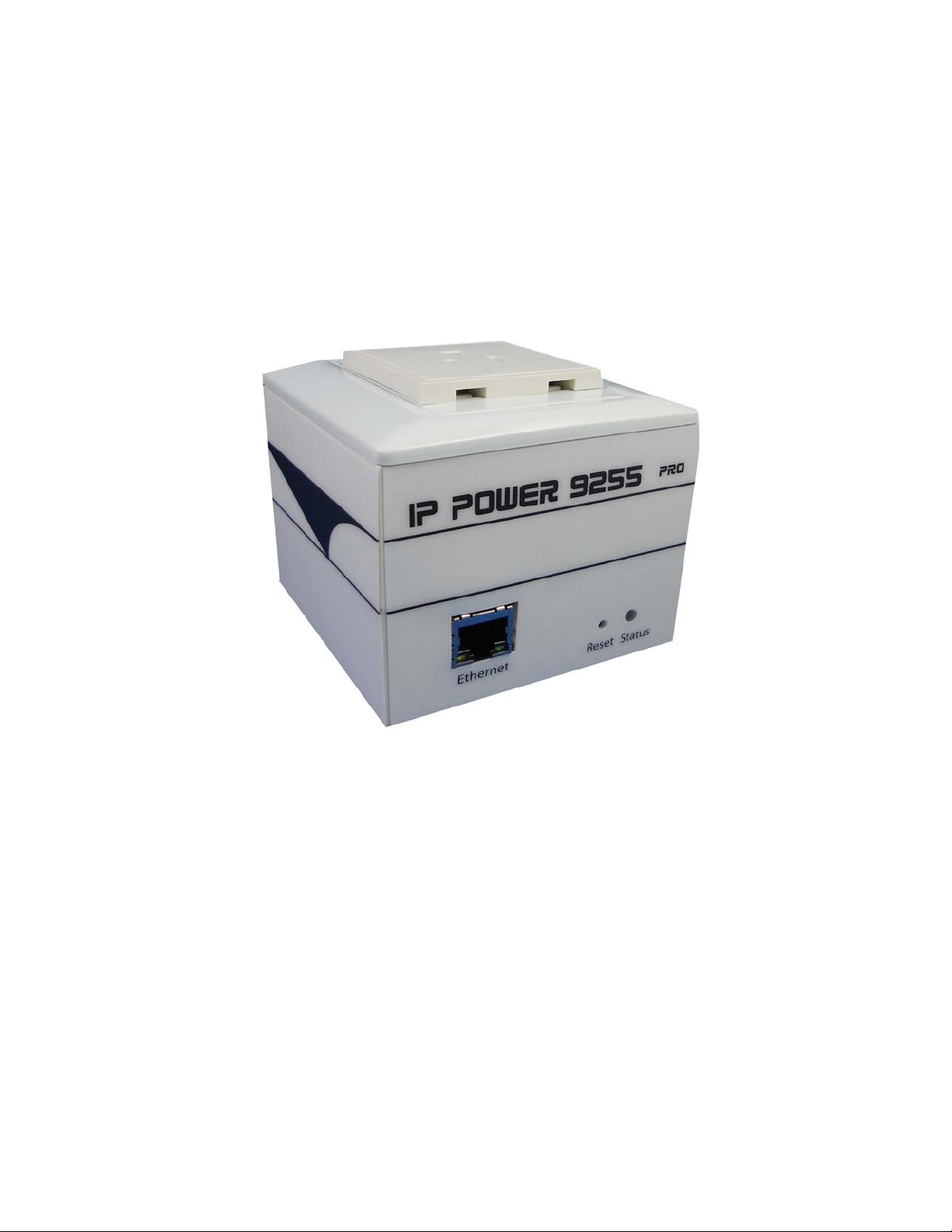
3.) Interface Description
standards)
long beeps.
Green Status Indicator: Output is On
Hardware Interface
Power Cable Input: The Power Input locates on the back of
the device.
Power Output
RJ45 Ethernet: Plug in the RJ45 Ethernet cable to the
RESET To revert to manufacturer default, hold
Status Indicator Red Status Indicator: Output port is
The Power output is on the top of the
device. Simply plug & play in the
device that you would like to power
control. (Comes in different plug
Ethernet port
down for 7-9 seconds until you hear 2
set to off
- 9-
Page 10

Ref#92550806002
4.) Setting up your Device
Before we Start
*Before setting up the device make sure of the following:
1.) All the package contents are all included if anything is missing please
contact the dealer where the device was purchased from.
2.) Check that the power input cable is working correctly.
3.) Check the cables to make sure there are no problems with the cable.
Setup for Internet Access
To access the 9255Pro from the internet, the router will require port forwarding to
be activated for your IP Power device.
* Please refer to your routers manual on how to port forward the device.
For example
9255Pro IP Address: 192.168.100.2 00
Port: 8080
* On the router you will need to port forward both TCP / UDP to the IP Address
192.168.100.200 on P or t 8080.
- 10-
Page 11

Ref#92550806002
9255Pro Quick I n stallation
1.) Connect the Ethernet cable (RJ45) to the 9255 to your local area network.
2.) Then connect the power cable into the power cable input of the 9255.
3.) Connect the device that you would like to control to the output plug on the top
of the 9255 .
4.) Open the IP Edit device search tool from the CD.
5.) The device will automatically be set to DHCP and will show on IP Edit. (Refer
to Using IP Edit for more details)
a. If no DHCP is detected the default IP and Login for the device will be
the following
Default IP: 192.168.1.100 (When no DHCP is apparent)
Default Login: admin
Default Password: 12345678
6.) Then on IP Edit double click on your device and a Internet Explorer window
will appear with the login screen.
7.) Simply login with the default login and password.
Default Login: admin
Default Password: 12345678
- 11-
Page 12

Ref#92550806002
Using IP Edit
IP Edit is a search tool designed to search, configure, or access the IP Power
9255 from a local networked computer.
IP Power 9255 Default Login / Password
Default IP: 192.168.1.100 (When no DHCP is apparent)
Default Login: admin
Default Password: 12345678
1.) Insert the CD provided with the product
2.) Install the software IP Edit to the desktop of your computer.
3.) Open IP Edit by clicking on the icon
4.) In the local devices section you will see your device show up if connected
correctly.
5.) Select the 9255 device and the device information will populate on the right.
6.) Check to see that the gateway IP and the IP Address (9255) match your
If not, type in the correct information, then hit the submit button to save changes.
- 12-
current network.
Page 13

Ref#92550806002
For example:
If you have the following information regarding the 9255 and your network
Gateway: 192.168.1.1
Computer IP Address: 192.168.1.122
9255 IP Address: 192.155.2.26
Sub Netmask: 255.255.255.0
Port: 8080
Since the IP Address of the 9255 is the following: 192.155.2.26
You will need to make sure that the first 3 segments of your 9255 IP Address
must match the first 3 segments of your gateway IP.
First 3 Segment of Gateway Address: 192.168.1.X
So your new IP Address for the 9255 should be: 192.168.1.26
New Network Information
9255 IP Address: 192.168.1.26
Gateway Address: 192.168.1.1
Local Computer IP Address: 192.168.1.122
Sub Netmask: 255.255.255.0
Port: 8080
7.) Press the rescan button to see if changes have been made.
- 13-
Page 14

Ref#92550806002
8.) Double click on the device in the local device section and an IE web browser
with the device login will pop up.
9.) Type in the default login and IP Address to enter the device.
New Network Information
9255Pro IP Address: 192.168.1.26
Gateway Address: 192.168.1.1
Local Computer IP Address: 192.168.1.122
Sub Netmask: 255.255.255.0
Port: 8080
Default Login/Password: admin/12345678
Using IP Service
IP Service is a feature which allows you to search for the device easily without
having to remember long complicated IP addresses. Instead, all you need to
know is the device name of your IP Power device and you can easily find it on IP
Service.
In the IP 9255Pro under the system configuration page, you can select the IP
server that you would like the 9255Pro to go to. You can select from the Aviosys
server or the Cloud Server. This function must be turned on to work.
* IP Power 9255Pro must be port forwarded for IP Service to work correctly.
1.) Open IP Edit and Select the server that your 9255Pro is designated to.
2.) Hit the green connect button on the top of IPEdit.
- 14-
Page 15

Ref#92550806002
3.) Then type in the 9255Pro Name that you have selected for the device and
press the search button.
4.) Find your device and double click on the screen and a IE window will pop up
connecting to your device.
*Your device must be Port forwarded for the login screen to appear.
5.) After you have connected to your device, type in the login and password for
your device
- 15-
Page 16

Ref#92550806002
5.) Web Interface
The web interface on the IP Power 9255Pro consists of 4 main sections. Power
Controls, Scheduler, Ping Settings, and Setup
Current & Temp. value : show the consume current ampere and internal
temperature at Celsius.
Power Controls: Turn off or Turn on the socket to provide power to the device.
and also the current setting & illustration and temperature value
Scheduler: Schedule specific dates or time to active the IP Power 9255Pro.
Ping Settings: Watchdog function to make sure your devices are responding
normally.
Setup: System Configuration
- System: Adjust main settings to device including IP Address, Gateway, Subnet
Mask, leakage current and et c.
- DDNS: Configure DDNS funct ion ality
- E-mail: Setup E-mail information
- Password: user can amend the password as number or English
character form 1 to 8 characters. (Maximum 8 digits)
Please do not use special sign like ~ ! @ # $ % ^ & * ( )
- Wake on Lan: Wake devices up that support wake on lan
- IP Service: Configure IP Service functionality to find devices by name
- Time: Setup time and date of device
Logout: Logout of the device
- 16-
Page 17

Ref#92550806002
Power Controls
The Power Controls page include power control and current limit setup
Power control
It is the panel where the user can directly turn off / on power to the attached
device, set timers and nam e the out let.
Name
In the name section the device name can be set. Simply type in a name you
would like for the deice and hit the apply button. Name does not support special
characters (eg. ! *%)
- 17-
Page 18

Ref#92550806002
Control
The control section allows the user to directly turn on or turn off the device.
Select the control that you would like to execute and hit apply to apply the
settings. This will turn the device on or off.
Timer
The timer allows the user to set an amount of time before a control is activated.
To do this, simply enter the amount of delay time in seconds you would like the
action to occur. Select the On or Off and hit the apply button. When the timer has
reached the time set it will execute your command.
For example if Port 1 is on and I would like to turn it off in 30 seconds, the
command may look something like the following.
* The maximum number of seconds that can be set on the timer of the device is
9999.
Current value, setting , consume chare & Temperature value
The Current and Temperature settings offers the current consume value ,
temperature value , current maximum setting and the consume current line chart
in one minutes so the user get the amp connected device consume also set the
maximum amp to protect over loading.
- 18-
Page 19

Ref#92550806002
Current Value : Show the consume ampere of the device connected with
9255Pro . The tolerance of the current measurement is plus or minus at 10%
degree.
Temperature Value : Show the internal temperatur e v alue at Celsius ( C ) .
working temperature range at -10°C ~ 50°C
Current Limit : Configure the maximum ampere of the connected device , if
over the limit value , 9255Pro will tu rn off the plug power in 5 seconds as
protection. User can set the limit from 1 to 9 amp.
Current line chart : Show the consume current value in 1 minute as connect to Internet . If not connect to
Internet , there is no line chart.
- 19-
Page 20

Ref#92550806002
Scheduler
The power schedule offers flexibility so the user can easily sch edule events to
control the power of the device.
Date: Enter the date in which the action will occur needs to be set.
Time: Enter the time of the action will occur.
Repeat: Select the frequency of this action.
Just Once (Just one time)
Everyday (Sunday thru Saturday)
Workdays (Monday thru Friday)
Weekend (Saturday, Sunday)
Mon. & Thu. (Monday, Thursday)
Tue. & Fri. (Tuesday, Friday)
Wed. & Sat. (Wednesday, Saturday)
How to use:
If you would like to turn on the device at 8:00AM and turn off the device at
8:00PM, the device may be set in this fashion.
- 20-
Page 21

Ref#92550806002
Ping Settings
The Auto-ping functionality allows the 9255Pro to check if the device have
malfunctioned or needs to be restarted. If the device is not working correctly the
9255Pro Ping will activate the action that you have selected to reinstate the state
of the device
Relay: A description of which on let to use Ping function
Enable: Disable or Enable ping settings
Ping IP Address: Speci fy the IP Address t o Pi ng
Ping Failures: The number of ping failures before the Action is activ ated.
Action Delay (Seconds): After the Ping Failures has been reached, you can set
the delay time (seconds) before the action is activated.
Some uses of this function would be for systems or computers that require a shut
down time
Delay after action (Seconds): The number of seconds it takes the attached
devices to startup. Once those devices start, the Startup Action will be activated
to continue pinging or stop pinging.
Continue Ping: After start up Delay has been reached the start up action will
either Continue Pinging or Stop Pinging
Action: When the number of Ping Failures have been reached. The device can
be set to perform a Off, On, or Reset function.
- 21-
Page 22

Ref#92550806002
Ping Type: Ping type sets a condition in the case where either all or 1 of the
conditions are met the action will be activated. For instance, if you set Ping Type
to "ALL", all the Ping IP's must fail for the action to be activated. On the other
hand if you set Ping Type to "OR" as long as one of the Ping IP fails it will cause
the action to be activated.
Ping Time Interval (Seconds): The number of seconds between each ping
Ping Response Time (Milliseconds): The number of milliseconds the device
will wait for a response from the pinged device if no ping is detected within this
time it will be considered a ping failure.
Please view the example below for more details:
In the picture above:
1.) Power 1 Ping function is enabled for two websites
2.) The 9255Pro will ping the web address www.sample.com &
www.google.com
3.) If there is a response within the Ping Response Time the 9255Pro will
send another ping signal the set Ping Time Interval which is 3 seconds for
this example.
4.) If the 9255Pro does not receive a response from the device it will constitute
a Ping Failure.
5.) After 3 consecutive failure the device will go to the Action Delay section. In
this case the device will delay for 3 seconds.
6.) When action delay has been reached the Action will be set off. Here we
have set the 9255Pro to Reset the device.
7.) Once the device has been reset the 9255Pro will go into Startup Delay
mode. In this case it is 3 seconds.
8.) After the startup delay mode has been reached the 9255Pro will check the
Startup Action whether to continue or stop pinging the device. Here we
have it set to Continue.
- 22-
 Loading...