

Avidyne IFD540 Installation Manual
IFD5XX Installation Manual
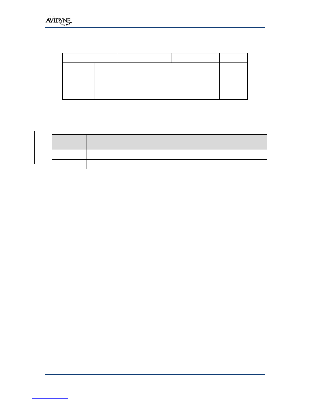
Revision
Number
Pages Changed
01
11, 87, Appendix D
02
11, 29, 33, 49, 56-61, 66-67, 70, 74, 79-81, 84, 86, 94, 121
Document Number
600-00299-000
Control Category
CC2
Revision
Description
ECO
Date
00
Initial Release
ECO-14-207
07/09/14
01
Release 10.0.1.0
ECO-14-283
08/21/14
02
Release 10.0.2.0
ECO-14-356
11/12/14
Revision History
Changed Pages
All materials copyrighted, including images that represent the software.
Copyright 2014 Avidyne Corporation. All rights reserved.
The latest installation manuals are available to authorized dealers on the web
at www.avidyne.com.
Avidyne® is a registered trademark of Avidyne Corporation.
600-00299-000 Page 2 of 198 Revision: 02

IFD5XX Installation Manual
Table of Contents
1. General Information ........................................................... 11
1.1 Introduction ............................................................................................................ 11
1.2 Applicability ............................................................................................................ 11
1.3 Technical Specifications ........................................................................................ 12
1.3.1 IFD5XX Specifications ....................................................................................... 12
1.3.2 Display Specifications ........................................................................................ 12
1.3.3 GPS Specifications ............................................................................................ 13
1.3.4 VHF Communication Transceiver Specifications .............................................. 14
1.3.5 VHF Navigation Specification ............................................................................ 15
1.4 Power Requirements ............................................................................................. 15
1.5 Regulatory Compliance ......................................................................................... 15
1.5.1 Applicable TSOs ................................................................................................ 15
1.5.2 TSO Deviations .................................................................................................. 17
1.5.3 Non-TSO Functions ........................................................................................... 19
1.5.4 Partial TSO Functions ........................................................................................ 20
1.5.5 Open Problem Report ........................................................................................ 20
1.6 Software and Hardware Design Assurance Levels ............................................... 21
1.7 Environmental Qualification Forms ........................................................................ 22
1.8 Databases .............................................................................................................. 22
1.9 Fault Detection and Exclusion (FDE) .................................................................... 22
1.10 STC Approved Model List ...................................................................................... 23
1.11 Avidyne Supplied Material ..................................................................................... 24
1.11.1 Product Ship Kits ........................................................................................... 24
1.11.2 Optional Ship Kits .......................................................................................... 24
1.12 Materials Required but not Supplied ..................................................................... 25
600-00299-000 Page 3 of 198 Revision: 02

IFD5XX Installation Manual
2. Installation Considerations................................................ 26
2.1 Plug & Play Considerations ................................................................................... 26
2.2 Optional Installation Features ................................................................................ 27
2.3 IFD5XX Interfaces ................................................................................................. 27
2.4 Minimum System Configuration ............................................................................. 33
2.4.1 VFR Installation ................................................................................................. 34
2.4.2 IFR Installation ................................................................................................... 34
2.5 Pre-Installation Checklist ....................................................................................... 37
3. Antenna Installation ........................................................... 38
3.1 Antenna Bonding ................................................................................................... 38
3.2 Antenna Environmental Qualifications ................................................................... 38
3.3 GPS Antenna ......................................................................................................... 38
3.3.1 GPS Location ..................................................................................................... 39
3.3.2 GPS Antenna Bonding....................................................................................... 41
3.3.3 GPS Antenna Cable .......................................................................................... 41
3.3.4 GPS Coaxial Cable Connector .......................................................................... 42
3.3.5 Approved GPS Antennas................................................................................... 42
3.3.6 GPS Interference ............................................................................................... 43
3.3.7 Ground Plane ..................................................................................................... 43
3.3.8 Dual IFD5XX Installations .................................................................................. 43
3.3.9 Anti-Ice Protection ............................................................................................. 43
3.4 VHF Communication Antenna ............................................................................... 43
3.4.1 Antenna Environmental Qualifications ............................................................... 43
3.4.2 VHF Communication Cable ............................................................................... 43
3.4.3 VHF Coaxial Cable Connector .......................................................................... 43
3.4.4 Voltage Standing Wave Ratio ............................................................................ 43
3.4.5 VHF Antenna ..................................................................................................... 44
600-00299-000 Page 4 of 198 Revision: 02

IFD5XX Installation Manual
3.4.6 Antenna Ground Plane ...................................................................................... 44
3.5 Navigation Antennas .............................................................................................. 44
3.5.1 VOR/LOC Antenna ............................................................................................ 44
3.5.2 Navigation Coaxial Cable .................................................................................. 44
3.5.3 Navigation Coaxial Cable Connector ................................................................. 44
3.5.4 Diplexer .............................................................................................................. 44
3.6 Glideslope Antenna ............................................................................................... 44
3.6.1 Glideslope .......................................................................................................... 44
4. Electrical Installation.......................................................... 45
4.1 Wire Type .............................................................................................................. 45
4.2 Wire and Connector Identification ......................................................................... 45
4.3 Wire Routing .......................................................................................................... 45
4.4 Shield Grounds ...................................................................................................... 45
4.5 Wire Harness Overbraid ........................................................................................ 45
4.5.1 Existing Equipment ............................................................................................ 45
4.5.2 Severe Lightning Transient Environment .......................................................... 45
4.5.3 Copper Overbraid Installation ............................................................................ 46
4.6 IFD5XX Connectors ............................................................................................... 46
4.7 Byteflight Digital Data Bus Consideration – Dual IFD Installations ....................... 46
4.7.1 Databus Wiring - Replacement Installations...................................................... 46
4.7.2 Databus Wiring – New Installations ................................................................... 47
4.8 Circuit Protection ................................................................................................... 47
4.9 Power Distribution .................................................................................................. 47
4.10 Electrical Load Analysis ......................................................................................... 49
4.11 Low Power Behaviors ............................................................................................ 49
5. Mechanical Installation ...................................................... 50
5.1 Equipment Location – New Installations ................................................................ 50
600-00299-000 Page 5 of 198 Revision: 02

IFD5XX Installation Manual
5.1.1 Determining the Field of View ............................................................................ 50
5.1.2 Navigation Annunciation .................................................................................... 51
5.1.3 Course Deviation Indicator ................................................................................ 53
5.1.4 Instrument Panel Cutout .................................................................................... 53
5.1.5 Requirements for Tray Installation ..................................................................... 53
5.2 Equipment Location - Replacement Unit ............................................................... 54
5.3 Angle of Regard ..................................................................................................... 54
5.4 Unit Installation/Removal ....................................................................................... 54
5.5 External Cooling .................................................................................................... 54
5.6 Electrical Bonding .................................................................................................. 54
5.7 Aircraft Considerations .......................................................................................... 54
5.8 Weight and Balance ............................................................................................... 55
5.9 Compass Safe Distance ........................................................................................ 55
6. System Installation ............................................................. 56
6.1 Pin Function List .................................................................................................... 56
6.1.1 P1001 Main Connector ...................................................................................... 56
6.1.2 P1002 Communication Connector ..................................................................... 58
6.1.3 P1006 Navigation Connector ............................................................................. 59
6.1.4 P1050 Additional I/O Connector ........................................................................ 60
6.1.5 Altitude Gray Code ............................................................................................ 61
6.1.6 Main Course Deviation Indicator Output............................................................ 62
6.1.7 Serial Data ......................................................................................................... 65
6.1.8 ARINC 429 ......................................................................................................... 65
6.1.9 Com/VOR/ILS Audio Electrical Characteristics ................................................. 66
6.1.10 VOR/ILS Indicator Electrical Characteristics ................................................. 67
6.1.11 DME Tuning ................................................................................................... 67
6.2 Bezel Lighting ........................................................................................................ 69
600-00299-000 Page 6 of 198 Revision: 02

IFD5XX Installation Manual
6.3 Traffic System ........................................................................................................ 69
6.4 Lightning Detection System ................................................................................... 69
6.5 Satellite Weather ................................................................................................... 70
6.6 Audio Panels .......................................................................................................... 70
6.7 GAD 42 .................................................................................................................. 70
6.8 Air Data System Sources....................................................................................... 72
6.9 Heading System Sources ...................................................................................... 73
6.10 Multifunction Displays ............................................................................................ 74
6.11 Terrain Alerting ...................................................................................................... 74
6.11.1 Audio .............................................................................................................. 75
6.11.2 Annunciators .................................................................................................. 75
6.12 ADS-B/Transponder Output .................................................................................. 75
6.13 Autopilot ................................................................................................................. 76
6.14 TAWS/EGPWS Output .......................................................................................... 76
7. Configuration and Checkout ............................................. 77
7.1 Wiring Check ......................................................................................................... 77
7.2 Mounting Check ..................................................................................................... 77
7.3 Chassis ID Setting ................................................................................................. 77
7.4 Unit Installation ...................................................................................................... 78
7.5 Configuration ......................................................................................................... 78
7.5.1 Maintenance Mode ............................................................................................ 78
7.5.2 ARINC 429 Port Configuration (Page 1 of 10) .................................................. 79
7.5.3 RS-232 Port Configuration (Page 2 of 10)......................................................... 84
7.5.4 Main System Configuration (Page 3 of 10)........................................................ 87
7.5.5 Main Input Configuration (Page 4 of 10)............................................................ 89
7.5.6 Main Lighting Configuration (Page 5 of 10) ....................................................... 89
7.5.7 Main CDI/OBS Config Page (Page 6 of 10) ...................................................... 93
600-00299-000 Page 7 of 198 Revision: 02

IFD5XX Installation Manual
7.5.8 VOR/LOC/GS CDI (Page 7 of 10) ..................................................................... 96
7.5.9 VOR/LOC/GS ARINC 429 Configuration (Page 8 of 10) .................................. 98
7.5.10 GPS Vertical Offset (Page 9 of 10) .............................................................. 100
7.5.11 GDL Configuration Pages (Page 10 of 10) .................................................. 101
7.5.12 GAD 42 Configuration .................................................................................. 102
7.5.13 Other System Diagnostics Pages ................................................................ 102
7.6 Checkout .............................................................................................................. 104
7.6.1 Database Check .............................................................................................. 104
7.6.2 Airplane Flight Supplement Check .................................................................. 104
7.6.3 Instructions for Continued Airworthiness ......................................................... 104
7.6.4 Aircraft Weight and Balance ............................................................................ 104
7.6.5 Electrical Load Analysis ................................................................................... 105
7.6.6 GPS Signal Acquisition .................................................................................... 105
7.6.7 VHF COM Checkout ........................................................................................ 105
7.6.8 VOR/LOC/ GS Checkout ................................................................................. 106
7.6.9 Autopilot ........................................................................................................... 106
7.6.10 Magnetic Compass Swing ........................................................................... 106
7.6.11 IFD5XX Bezel and Display Lighting ............................................................. 106
7.6.12 External Annunciators and Switches ........................................................... 106
7.6.13 Placards ....................................................................................................... 106
7.6.14 Self-test Page .............................................................................................. 107
7.6.15 Dual IFD5XX Configuration ......................................................................... 107
7.6.16 AHRS/IRU Interface Check ......................................................................... 108
8. Flight Checks .................................................................... 109
8.1 GPS Flight Test ................................................................................................... 109
8.2 VHF COM Flight Check ....................................................................................... 109
8.3 VOR Flight Checks .............................................................................................. 109
600-00299-000 Page 8 of 198 Revision: 02

IFD5XX Installation Manual
8.4 ILS Flight Test ...................................................................................................... 109
8.5 Autopilot ............................................................................................................... 109
8.6 Sensors ................................................................................................................ 110
9. Glove Validation Procedures ........................................... 111
10. Software and Database Update Procedures ............. 112
10.1 Data Updates ....................................................................................................... 112
10.2 Datalogs Download .............................................................................................. 115
10.3 Software Update .................................................................................................. 117
11. Periodic Maintenance ................................................. 118
11.1 Equipment Calibration ......................................................................................... 118
11.2 VOR Checks ........................................................................................................ 118
11.3 Cleaning ............................................................................................................... 118
12. Factory Service Policies and Procedures ................. 119
12.1 Technical Support ................................................................................................ 119
12.2 General Service Procedures ............................................................................... 119
13. Bezel and Display Cleaning ....................................... 120
Appendix A: Environmental Qualification Form ................... 121
Appendix B: STC Permission ................................................ 122
Appendix C: Mechanical Drawings ....................................... 123
Appendix D: Electrical Interface Drawings ........................... 128
Appendix E: Troubleshooting Guide ..................................... 179
Appendix F: Configuration Setup .......................................... 181
600-00299-000 Page 9 of 198 Revision: 02

IFD5XX Installation Manual
1. These installation instructions assume that the
GPS/NAV/COM transceiver and GPS antenna can be
installed in a structurally sound manner in accordance with
the installation manual and AC 43.13-( ). All the aircraft
certification requirements must remain in compliance.
2. Mounting the GPS antenna on composite and pressurized
aircraft requires engineering guidance beyond the scope of
this manual. With respect to the Approved Model List STC,
the physical mounting of the antenna is specifically
excluded from the approval in the case of installations on
the pressure vessel of pressurized aircraft, composite
aircraft, and aircraft with a certification basis of
Amendment 23-45 or later, unless approved installation data
is listed in the Master Document List of the STC. All early
amendment, metal construction, non-pressurized aircraft
antenna installations must be installed consistent with
accepted industry practices. The installation must be
structurally sound and in accordance with FAA Advisory
Circular 43.13-1B and 43.13-2B. All other antennas must be
mounted using the manufacturers' installation data.
3. An Electrical Load Analysis must be accomplished to
determine that the electrical limits of the specific aircraft are
not exceeded. The Electrical Load Analysis, Functional
Hazard Assessment and other certification requirements for
the aircraft must remain in compliance.
4. The IFD5XX Forward Looking Terrain Alerting is not a
TSO-C151 system, and does not satisfy any Part 91/135
TAWS requirements.
5. Prior to starting IFD5XX installation, verify the aircraft
make and model is on the STC Approved Model List
(AML). Also, note any installation specific data for the make
and model in the AML.
Notes to Installers:
The following important issues regarding the Avidyne 700-00182-XXX GPS/NAV/COM
System installation should be noted during the planning stages.
600-00299-000 Page 10 of 198 Revision: 02
IFD5XX Installation Manual
Model Number
Hardware Part Number
Software Part Number
(or later approved revision)
IFD540 (Black Bezel, 10W)
700-00182-000
ACR: 530-00225-000 Rev. 02
510-00286-000 Rev. 02
510-00287-000 Rev. 01
510-00310-000 Rev. 00
510-00311-000 Rev. 00
510-00312-000 Rev. 00
FPSM: 530-00226-000 Rev. 00
510-00294-000 Rev. 00
510-00291-000 Rev. 00
LIO App: 530-00227-000 Rev. 00
510-00293-000 Rev. 00
510-00292-000 Rev. 00
LIO I/O: 530-00228-000 Rev. 00
510-00288-000 Rev. 00
510-00289-000 Rev. 00
510-00290-000 Rev. 00
510-00291-000 Rev. 00
GPS: 530-00229-000 Rev. 02
510-00876-000 Rev. 02
510-00877-000 Rev. 01
VHF: 530-00231-000 Rev. 00
510-00314-000 Rev. 00
510-00239-001 Rev. 00
510-00316-000 Rev. 00
510-00237-000 Rev. 00
IFD540 (Black Bezel, 16W)
700-00182-002
IFD540 (Gray Bezel, 10W)
700-00182-100
IFD540 (Gray Bezel, 16W)
700-00182-102
1. General Information
1.1 Introduction
This manual contains information about the physical, mechanical, and electrical
characteristics of the Avidyne IFD5XX GPS/Navigation/Communication, and provides
installation instructions for its components.
1.2 Applicability
This manual applies to the following part numbers:
600-00299-000 Page 11 of 198 Revision: 02
Table 1: IFD5XX Variants

IFD5XX Installation Manual
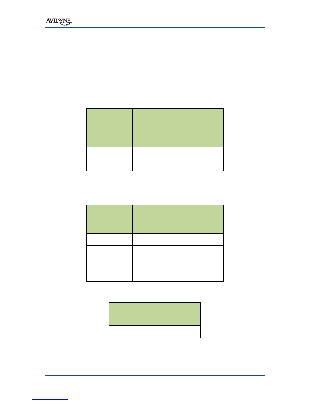
Physical Specifications
Bezel Height
4.58 inches (116 mm)
Bezel Width
6.25 inches (159 mm)
Depth (w/Connectors)
11.00 inches (279 mm)
Weight
6.75 ± 0.25 lbs (2.59 kg)
Connectors (Aircraft Mating Connector)
P1001/P1050 - 78-position High Density D-
Subminiature (male)
P1002- 25-position Standard D- Subminiature
(female)
P1006- 44-position High Density D-
Subminiature (male)
Electrical Requirements
Voltage
9-33 VDC
Current
4.4A main, 6.5A COM, 0.25A NAV at 14VDC
2.2A main, 4A COM, 0.50A NAV at 28VDC
Dimming Bus
28VDC/14VDC/5VDC/5VAC
Cooling Requirements
Not Required
Operating Limits
Reference Appendix A: Environmental
Qualification Form
Display Size
5.7 inches diagonal
Active Area
4.53 inches (w) x 3.40 inches (h)
Resolution
640x480 pixels
Viewing Angle
Left/Right: 80°
Up: 80°
Down: 60°
1.3 Technical Specifications
The following section gives mechanical and electrical characteristics for the IFD5XX:
1.3.1 IFD5XX Specifications
1.3.2 Display Specifications
600-00299-000 Page 12 of 198 Revision: 02
Table 2: IFD5XX Specifications
Table 3: IFD5XX Display Specifications

IFD5XX Installation Manual
Channels
16 channels (13 GPS, 3 GPS/WAAS/SBAS)
Velocity
1000 knots maximum (below 60,000 ft)
TTFF (Time to First Fix)
150 seconds
Reacquisition
20 seconds
Position Update Interval
0.2 seconds (5 Hz)
Lat/Long Position Accuracy
3.4 meters
Fault Detection/RAIM
RAIM/FDE WAAS Beta 3 Compliant @ 5 Hz
Sensitivity
-123 dBm
GPS System Design Assurance (SDA)
DO-178B Level B, DO-254 Level B
GPS Source Integrity Level (SIL)
3 – Enroute
Source Integrity Level Supplement (SIL
SUPP
)
0 – “per hour”
Navigation Accuracy Category Velocity
(NACV)
Category 3 (ADS-B installations should use a
NACv of 1 unless GPS tests support a higher
category)
Receiver Class
TSO-C146c Class Gamma 3 receiver that
complies with AC 20-138C
1.3.3 GPS Specifications
Table 4: IFD5XX GPS Specifications
600-00299-000 Page 13 of 198 Revision: 02

IFD5XX Installation Manual
Audio Output
65 mW into 150 load
Audio Response
<6dB Variation from 350 to 2500 Hz, 4kHz -18dB
AGC Characteristics
<6dB Variation from 10uV to 10mV
Sensitivity
4uV (6dB (S+N)/N 30% mod @ 1KHz)
Spurious Response
10mV spurious signal produces no more output than a
desired signal at 6dB (S+N)/N
Transmitter Power
16W @ 28V, 10W @ 14V (Typical)
Transmitter Duty Cycle
Recommended 10% maximum
Modulation Capability
70%
Carrier Noise Level
-39dB (S+N)/N
Frequency Stability
>2.5 ppm
Demodulation Audio
Distortion
<12% @ 70% modulation
Sidetone Fidelity
300-2500 Hz
Demodulation Audio
Response
<6dB Variation from 300 to 2500 Hz
1.3.4 VHF Communication Transceiver Specifications
Table 5: VHF Communication Transceiver Specifications
600-00299-000 Page 14 of 198 Revision: 02
IFD5XX Installation Manual
Glideslope Receiver
-
Selectivity
0 +/-.0091 ddm w/ test signal varied +/-17kHz. 60dB for
+/- 132kHz offset
Sensitivity (flag)
10uV max
Spurious Response
>-60 dB
Centering Accuracy
0 ± 0.02 DDM or better
Deflection Response
67% of final value in 600msec
Localizer Receiver
-
Selectivity
6dB at least ±17kHz, 40dB no more than ±80kHz
Sensitivity (flag)
10uV max
Sensitivity (aural)
10uV max for 20dB (S+N)/N with 1kHz 30%mod
Centering Accuracy
+/-3mV
Deflection Response
67% of final value in 600msec
Audio Response
<6dB Variation from 350 to 2500 Hz,
-20dB <150Hz >9kHz
Voltage
14VDC
28VDC
Main Power
4.4A
2.2A
COM Power
6.5A
4.0A
NAV Power
0.25A
0.50A
1.3.5 VHF Navigation Specification
Table 6: VHF Navigation Specification
1.4 Power Requirements
The IFD5XX is capable of operating from 9-33 VDC. The following table shows the typical
current requirements for 14VDC and 28VDC aircraft electrical systems.
Table 7: Power Requirements
1.5 Regulatory Compliance
1.5.1 Applicable TSOs
This section identifies Technical Standard Orders (TSOs) applicable to the IFD5XX system.
The conditions and tests required for TSO approval of this article are minimum performance
standards. It is the responsibility of those installing this article either on or within a specific
type or class of aircraft to determine that the aircraft installation conditions are within the
TSO standards. TSO articles must have separate approvals for installation in aircraft. The
600-00299-000 Page 15 of 198 Revision: 02

IFD5XX Installation Manual
TSO
Number
Title
Type/Categories
Ranges
TSO-C34e
ILS Glide Slope Receiving
Equipment Operating within
the Radio Frequency Range of
328.6-335.4 Megahertz (MHz)
TSO-C36e
Airborne ILS Localizer
Receiving Equipment
Operating within the Radio
Frequency Range of 108-112
Megahertz (MHz)
TSO-C40c
VOR Receiving Equipment
Operating within the Radio
Frequency Range of 108-
117.95 Megahertz (MHz)
TSO-C44c
Fuel Flowmeters
TSO-C110a
Airborne Passive
Thunderstorm Detection
Equipment
TSO-C113a
Airborne Multipurpose
Electronic Display
TSO-C118
Traffic Alert and Collision
Avoidance System (TCAS)
Airborne Equipment, TCAS I
TSO-C128a
Devices that Prevent Blocked
Channels Used in Two-Way
Radio Communications Due
to Unintentional
Transmissions
TSO-C146c
Stand-Alone Airborne
Navigation Equipment Using
the Global Positioning System
(GPS) Augmented by the
Wide Area Augmentation
System (WAAS).Airborne
Supplemental Navigation
Equipment Using the Global
Positioning System (GPS) -
Gamma 3
article may be installed only if performed under 14 CFR Part 43 or the applicable
airworthiness requirements.
600-00299-000 Page 16 of 198 Revision: 02

IFD5XX Installation Manual
TSO
Number
Title
Type/Categories
Ranges
TSO-C147
Traffic Advisory System
(TAS) Airborne Equipment
Class A (Display
Functions Only)
TSO-C157a
Aircraft Flight Information
Services – Broadcast (FIS-B)
Datalink Systems and
Equipment
TSO-C165
Electronic Map Display
Equipment for Graphical
Depiction of Aircraft Position
TSO-C169a
VHF Radio Communications
Transceiver Equipment
Operating Within The Radio
Frequency Range 117.975 To
137.000 Megahertz
Class C, E, 3 and 5
TSO
Deviation(s)
TSO-C34e - ILS Glideslope Receiving
Equipment
1. Environmental qualification
performed in accordance with DO160G rather than DO-160B.
TSO-C36e - Airborne ILS Localizer Receiving
Equipment
1. Environmental qualification
performed in accordance with DO160G rather than DO-160B.
TSO-C40c - VOR Receiving Equipment
1. Environmental qualification
performed in accordance with DO160G rather than DO-160B.
TSO-C44c - Fuel Flowmeters
1. Environmental qualification
performed in accordance with DO160G rather than a combination of
DO-160B and AS407C. AS407C
requirements apply to portions of the
instrument not implemented by the
IFD system;
2. The fuel flow indicators will not use
matte white material for all
graduations, numerals, pointers and
indicators. Color coded indications
Table 8: IFD5XX TSO Functions
1.5.2 TSO Deviations
600-00299-000 Page 17 of 198 Revision: 02

IFD5XX Installation Manual
TSO
Deviation(s)
are used where appropriate for rapid
pilot recognition of exceedances;
3. The fuel flow indicators are a digital
readout instead of pointer and dial.
TSO-C110a – Airborne Passive
Thunderstorm Detection Equipment
1. Environmental qualification
performed in accordance with DO160G rather than DO-160B.
TSO-C113a – Airborne Multipurpose
Electronic Display
1. The IFD5XX display response time is
not less than 1 second during ShortTime Operating Low Temperature
environmental conditions as defined
in Section 4.0 of RTCA/DO-160G.
TSO-C118 - Traffic Alert and Collision
Avoidance System (TCAS) Airborne
Equipment, TCAS I
1. Environmental qualification
performed in accordance with DO160G rather than DO-160B.
2. The IFD5XX used the minimum
performance standards set forth in
the Radio Technical Commission for
Aeronautics (RTCA) Document No.
RTCA/DO-197A, “Minimum
Operational Performance Standards
for An Active Traffic Alert and
Collision Avoidance System I (Active
TCAS 1),” Section Two (2) September
12, 1994 with the exceptions listed in
appendix 1 of TSO-147 in lieu of the
corresponding minimum operational
performance standards specified in
the TSO.
TSO-C128a - Equipment that Prevents
Blocked Channels used in two-ways
Radio Communications due to
unintentional transmissions
1. Environmental qualification
performed in accordance with DO160G rather than DO-160B.
TSO-C146c - Stand-alone Airborne
Navigation Equipment using the Global
Position System augmented by the
Satellite based Augmentation System
1. Environmental qualification
performed in accordance with DO160G rather than DO-160B.
TSO-C147 – Traffic Advisory System (TAS)
Airborne Equipment
1. Environmental qualification
performed in accordance with DO160G rather than DO-160B;
2. The IFD5XX map does not place a
range ring at 2 NM from the own
aircraft symbol when a display range
600-00299-000 Page 18 of 198 Revision: 02

IFD5XX Installation Manual
TSO
Deviation(s)
of 10 NM or less is selected;
TSO-C157a – Aircraft Flight Information
Services – Broadcast (FIS-B) Data Link
Systems and Equipment
1. Smoothing and scaling algorithms at
high map ranges remove small
patches of high-intensity NEXRAD
returns in favor of surrounding
lower-intensity returns.
TSO-C165 – Electronic Map Display
Equipment for Graphical Depiction of
Aircraft Position
1. Environmental qualification
performed in accordance with DO160G rather than DO-160B;
2. De-cluttering on chart page not
provided.
3. Location of traffic symbols in the
absence of heading information
TSO-C169a - VHF Radio Communications
Transceiver Equipment
1. Environmental qualification
performed in accordance with DO160G rather than DO-160B.
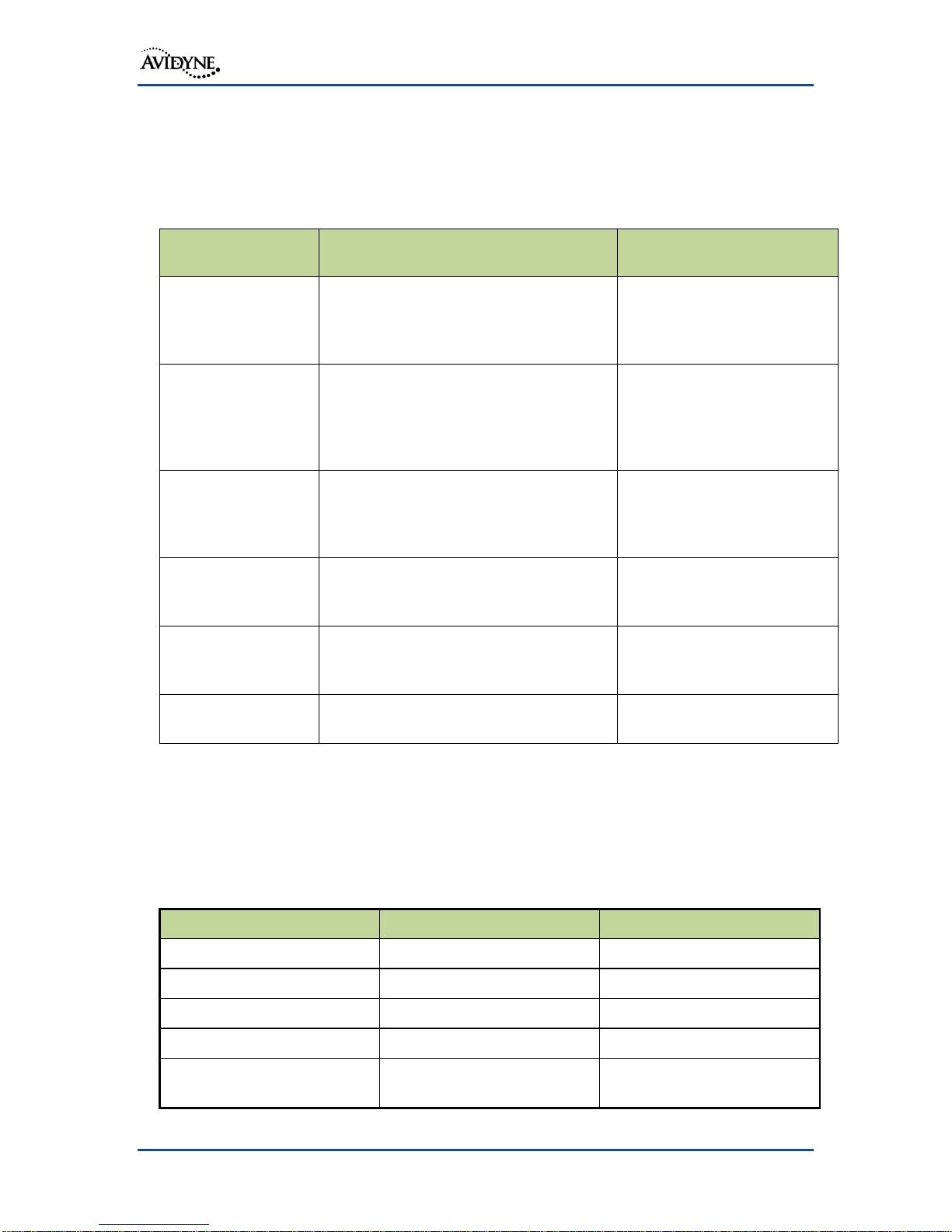
IFD5XX Function
Display of Terrain Alerting
Display of Aircraft Checklists
Calculators (Air Data, Fuel Planner, etc)
Display of Timers and Schedulers
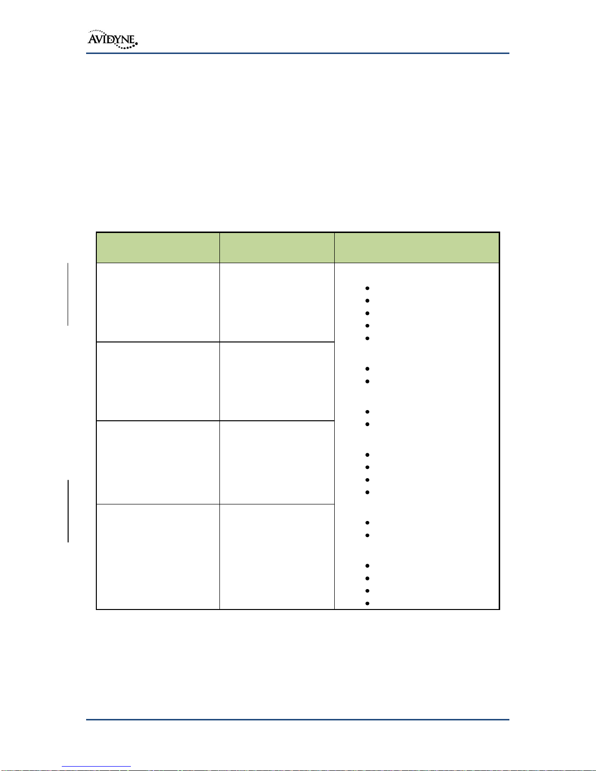
Table 9: IFD5XX TSO Deviations
Table 9 above lists the TSO Deviations and a brief description of the nature of the deviation
that have been granted for those applicable TSOs.
1.5.3 Non-TSO Functions
The following IFD5XX functions are not TSO’d:
Table 9: Non-TSO Functions
600-00299-000 Page 19 of 198 Revision: 02

IFD5XX Installation Manual
TSO
Description
Comment
TSO-C44c
Fuel Flowmeters
Display Only
TSO-C110a
Airborne Passive Thunderstorm Detection
Equipment
Display Only
TSO-C118
Traffic Alert and Collision Avoidance
System (TCAS) Airborne Equipment,
TCAS I
Display Only
TSO-C147
Traffic Advisory System (TAS) Airborne
Equipment
Display Only
TSO-C157a
Aircraft Flight Information Services -
Broadcast (FIS-B) Datalink Systems and
Equipment
Display Only
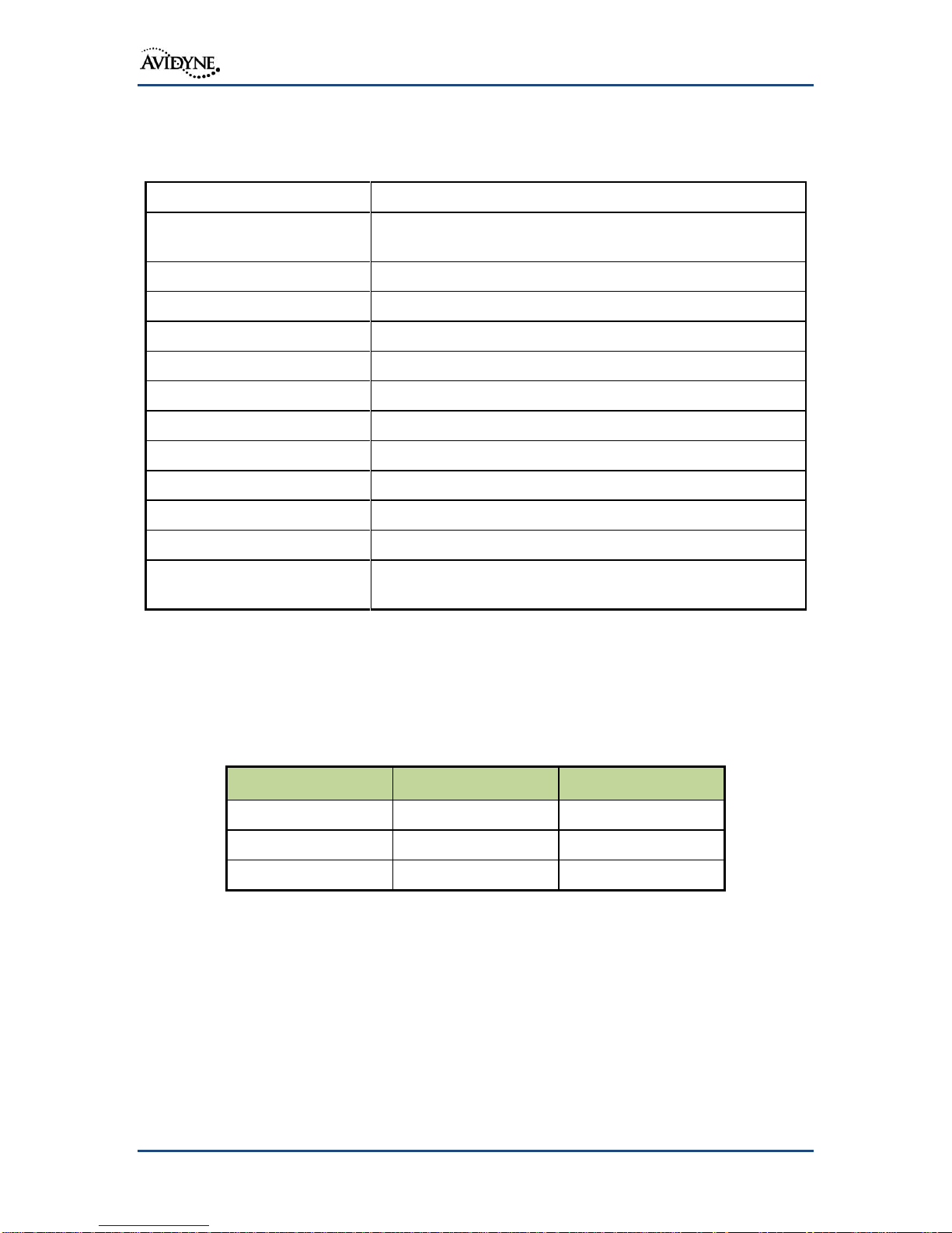
1.5.4 Partial TSO Functions
The following IFD5XX TSOs are partial function:
Table 10: Partial Function TSOs
1.5.5 Open Problem Report
At the time of this revision, the IFD5XX does not have any open problems that affect safety or
design assurance level of the unit.
600-00299-000 Page 20 of 198 Revision: 02

IFD5XX Installation Manual
Component
Function
DO-178B Design
Assurance Level
IFD5XX
Traffic
D
Lightning
D
Digital Moving Map
(not including Terrain)
C
Terrain Alerting
C
Wx Datalink
D
FMS
B
VHF Communication
C
VHF Navigation
C
GPS Navigation
B
Checklist
C
Fuel Display
C
Charts
C
Timers/Schedulers
D
Calculators
D
1.6 Software and Hardware Design Assurance Levels
The IFD5XX contains software developed in accordance with DO-178B Level B, C, and D
design assurance levels. The following table lists functions of the IFD5XX system and their
corresponding software design assurance level.
All complex electronic hardware devices were developed in compliance with DO-254 Level
B.
600-00299-000 Page 21 of 198 Revision: 02

IFD5XX Installation Manual
Component
Function
DO-178B Design
Assurance Level
Maintenance Mode
D
Table 11: DO-178B Software Design Assurance Levels
1.7 Environmental Qualification Forms
The environmental Qualification for the IFD5XX is listed in Appendix A: Environmental
Qualification Form.
Note: If the IFD5XX has been exposed to extreme cold temperature prior start, it may take a
warm up period to achieve standard performance.
1.8 Databases
The IFD5XX utilizes several databases. All the databases can be loaded on the IFD using the
USB port on the IFD5XX. Reference the IFD5XX Pilot’s Guide for updating the IFD5XX
databases.
1.9 Fault Detection and Exclusion (FDE)
FDE software is part of all IFD5XX systems and does not require any installer or pilot action
to operate. This FDE software is running at all times and if it detects an issue, it will alert the
pilot through Caution-Alerting System (CAS) messages.
When the IFD5XX is installed per the directions in this Installation Manual, it complies with
the governing requirements for GPS Primary Means of Navigation in Oceanic and Remote
Airspace (more than 200 nm from the nearest airport), when used with any commercially
available RAIM/FDE Prediction Program. Examples of these prediction programs include
the FAA’s raimprediction.net, Fltplan.com, www.sapt.faa.gov, and the Garmin FDE
Prediction Program.
These programs only need to be run under the following scenarios for 14 CFR Parts 91, 121,
125, and 135 operations where the IFD5XX is being used as the primary means of navigation
and:
TSO-C146 compliant antenna equipped aircraft that experience a
WAAS failure or when operating outside of SBAS coverage areas;
Non-TSO-C146 compliant antenna equipped aircraft (e.g. TSO-C129a
only compliant systems) when operating in Oceanic and Remote
airspace, Enroute and Terminal airspace, or during any
LNAV/VNAV, LP, or LPV approach.
Prior to conducting Class II navigation (remote/oceanic), the owner/operator must obtain
operational approval for using the IFD5XX system for long-range navigation from the
appropriate flight standards district office.
600-00299-000 Page 22 of 198 Revision: 02

IFD5XX Installation Manual
1.10 STC Approved Model List
The aircraft listed on the Approved Model List STC are eligible to install the IFD5XX.
However, the installer must determine if the installation is in compliance with the limitations
stated in the STC and this manual. Any deviations from the STC and/or this manual must
have a separate installation approval.
Installations in Part 25/27/29 aircraft or Part 23 airplanes not listed on the AML STC may
install the IFD5XX, however, it will require additional installation approval (e.g. Field
approval, STC, or TC amendment), reference FAA Advisory Circular 23-22 as needed. If
installing a IFD5XX on a Part 27/29 aircraft via field approval, the Avidyne Helicopter tray
must be used, reference Table 13.
The installation of antennas on composite and/or pressurized aircraft requires engineering
guidance beyond the scope of this manual. With respect to the Approved Model List STC, the
physical mounting of the antenna is specifically excluded from the approval in the case of
installation on the pressure vessel of a pressurized aircraft, composite aircraft, and aircraft
with a certification basis of Amendment 23-45 or later, unless approved installation data is
listed in the Master Document List of the STC. All early amendment, metal construction, nonpressurized aircraft may install the GPS antenna using this manual. The installation must be
structurally sound and in accordance with FAA Advisory Circular 43.13-( ). All other
antennas must be installed using the antenna manufacturer's installation data or FAA
Advisory Circular 43.13-( ).
600-00299-000 Page 23 of 198 Revision: 02
IFD5XX Installation Manual
Component
Ship Kit
850-00182-000
Black Bezel
Ship Kit
850-00183-100
Grey Bezel
IFD5XX Unit
700-00182-000
700-00182-100
USB Flash Drive
X
X
Component
Fixed Wing
Aircraft
Ship Kits
Helicopter
Ship Kit
IFD5XX Tray
850-00188-000
850-00188-001
IFD5XX
Components Only
(no tray)
820-00113-000
820-00113-000
IFD5XX Tray and
Install Kit
850-00188-002
850-00188-003
Component
Ship Kit
850-00217-000
GPS Antenna
200-00260-000
1.11 Avidyne Supplied Material
The following Ship Kits are available for ordering from Avidyne Corporation.
Note: Ship Kit content and/or Part numbers may change without notice, verify before
ordering.
1.11.1 Product Ship Kits
1.11.2 Optional Ship Kits
Table 12: IFD5XX Ship Kit
Table 13: IFD5XX Optional Ship Kits
600-00299-000 Page 24 of 198 Revision: 02
Table 14: GPS Antenna Kit

IFD5XX Installation Manual
Component
Ship Kit
820-00101-001
ByteFlight Cable
033-00102-000
Table 15: ByteFlight Ship Kit
1.12 Materials Required but not Supplied
The IFD5XX will require common installation supplies. The following items may be required
for installation, but not supplied:
Wire (Shielded and Un-shielded)
Hardware (Screws, washers, nuts, ring terminals, etc)
Circuit Breakers
Tie wrap or Lacing Cord
Coaxial Cables
Wire Splices
Solder Sleeves
Antenna(s)
Diplexers
600-00299-000 Page 25 of 198 Revision: 02

IFD5XX Installation Manual
Note: Installations replacing an existing non-WAAS GPS/NAV/COM
transceiver cannot upgrade to a WAAS installation without performing a
major alteration.
Note: Installations replacing a GNS-530/W must verify the aircraft is on the
IFD5XX Approved Model List, Avidyne Document Number AVIFD-318.
Note: It is imperative that only one source of terrain cautions and warnings be
enabled on the airplane so as to avoid the potential for conflicting
information to be presented to the pilot. If a TAWS system is installed but
the IFD's internal TA and FLTA functions are to be used for terrain
avoidance, the TAWS system must be fully disabled. If a TAWS system is
to be used, its type must be properly configured on the IFD so that the
caution and warning indications generated by the TAWS system can be
displayed to the pilot and so that the IFD's TA and FLTA functions will be
inhibited.
Avidyne TA/FLTA is not approved TSO-C151 EGPWS unit.
The IFD system supports a Honeywell KGP560/860 system only. All other
external TAWS/EGPWS systems must be disable if the internal TA and
FLTA is operational on the IFD system.
2. Installation Considerations
The following section will describe installation instructions for the IFD5XX Unit. The IFD5XX
should be installed using standard industry practice while following guidance in FAA AC
43.13-( ), AC 20-138 ( ), and AC 20-67( ).
2.1 Plug & Play Considerations
The IFD5XX is designed to be a slide-in replacement for a GNS-530/W. For those
replacement installations in fixed wing aircraft, the existing aircraft tray and wiring can all be
reused. However, all electrical wiring, including power(s) and ground(s), should be verified
per installation data shown in Appendix D: Electrical Interface Drawings. Note that 14v
aircraft may be required to replace the installed circuit breaker and power and ground wiring
to accommodate the IFD5XX.
If the unit being replaced was a WAAS-enabled device, then the WAAS antennas previously
installed can be reused, assuming they are one of the GPS WAAS antennas identified in
Section 3.3.5.
If the unit being replaced was not a TAWS-enabled device, or if the TAWS Audio output
signals were not already connected to the aircraft audio panel(s), then some additional wiring
will be required from the IFD5XX tray to the aircraft audio panel(s) as identified in Section
6.11.1 in order to supply IFD5XX terrain alerting audio (FLTA functionality) and TOD chime
to the headsets. If the unit being replaced was a TAWS-enabled device used for 91/135
TAWS compliance, the IFD5XX cannot be installed without a separately installed
EGWPS/TAWS unit.
For those installations that use a combined IFD5XX – Avidyne AXP340 Mode S ADS-B
transponder, the on-ground/in-air discrete signal wire may need to be added from the
IFD5XX tray to the AXP340 tray as identified in Section 6.12.
600-00299-000 Page 26 of 198 Revision: 02
IFD5XX Installation Manual
Feature
Description
Reference Section for
Installation Details
Audio Panel Aurals
Allows IFD5XX produced aural alerts
(e.g. FLTA terrain alerts, Top of Descent
alerts, 500’ callouts, etc) to be heard in
the headsets.
Section 6.11.1
Transponder
Support
Allows IFD5XX GPS position
transmission to the transponder for
ADS-B operation and IFD5XX
Air/Ground output to the transponder
for automatic Ground-Alt transition.
Section 6.12
Com Presets
Enables external command (e.g. yokemounted button) to select frequencies in
the com preset list to be loaded into the
#1 Standby com slot.
Section 6.1.9.4
Com Frequency
Active-Standby
Swap
Enables external command (e.g. yokemounted button) to swap the Active and
#1 Standby com frequencies.
Section 6.1.9.4
Nav Frequency
Active-Standby
Swap
Enables external command (e.g. yokemounted button) to swap the Active and
#1 Standby nav frequencies.
Section 6.1.9.4
Synchro Heading
Input
Allows the IFD5XX to take heading data
in via synchro protocol.
Section 6.1.2
Category
Vendor
Model
Air Data
B&D
2600 ADC
B&D
2601 ADC
B&D
2800 ADC
B&D
900004-003 ADC
Bendix King
KAD 280/480 ADC (KDC
281, 481)
All installations must verify the aircraft complies with either Section 2.4.1 or 2.4.2 after
completing the IFD5XX installation.
2.2 Optional Installation Features
This section summarizes optional features that may require extra wiring.
2.3 IFD5XX Interfaces
The IFD5XX can interface with a host of other avionics equipment. The following list
represents the proven interfaces. There may be other devices that can be configured the same
as one on the below list but Avidyne has not tested it and can therefore not make any
compatibility claims.
600-00299-000 Page 27 of 198 Revision: 02
Table 16: Optional Installation Features

IFD5XX Installation Manual
Category
Vendor
Model
Shadin
8800T Alt Computer
Shadin
9000T Alt Computer
Shadin
9200T Alt Computer
Shadin
9628XX-X Fuel/Air Data
Computer
Insight
TAS 1000 ADC
Icarus
Instrument 3000
Sandia
SAC7-35
Garmin
GDC74A
Encoding Altimeter or Blind
Encoders
Bendix King
KEA-130A
Bendix King
KEA-346
Terra
AT-3000
Sandia
SAE5-35
Trans-Cal Industries
IA-RS232-X
Trans-Cal Industries
SSD120
ACK Technologies
A-30
EFIS
Bendix King
EFS 40/50
Avidyne
EXP5000
Aspen
Pilot PFD (EFD1000)
Collins
Proline 21
Collins
EFIS 84
Honeywell
Primus 1000
Sextant
SMD 45
Displays
Garmin
GDU 620 (G500/600)
Garmin
MX20
Garmin
GMX200
Garmin
GPSMAP 195
Garmin
GPSMAP 295
Garmin
GPS III Pilot
Garmin
GPSMAP 196
Garmin
GPSMAP 296
Garmin
GPSMAP 396
600-00299-000 Page 28 of 198 Revision: 02

IFD5XX Installation Manual
Category
Vendor
Model
Garmin
GPSMAP 496
Garmin
GPSMAP 695
Garmin
GPSMAP 696
Garmin
Aera 796/795
Argus
3000
Argus
5000
Argus
7000
Horizon
DDMP
Avidyne
EX500
Avidyne
EX600
Avidyne
EX5000
Avidyne
FlightMax Series
Heading
Bendix King
KAH 460 Inertial System
(KAU 461 also)
Collins
AHC 85 Inertial System
Laseref
Honeywell
HG 1075AB, HG 1095AG
Inertial Systems
Litef
LTR 81 Inertial System
Litton
LTN 90-100 Inertial System
Litton
LTN 91 Inertial System
Litton
LTN 92 Inertial System
EHSI
Sandel
SN3308
Sandel
SN3500
Fuel
Shadin
91053XP Digital Fuel Mgmt
System
Shadin
91204XM Digital Fuel Mgmt
System
Shadin
91802-X Fuel/Airdata
JPI
EDM-700 Engine Monitor
JPI
EDM-760 Engine Monitor
JPI
FS-450
ARNAV
FC-10
ARNAV
FT-10
600-00299-000 Page 29 of 198 Revision: 02

IFD5XX Installation Manual
Category
Vendor
Model
EI
FP-5L
Insight
GEM 3
Traffic
L3
SKY497 SkyWatch
L3
SKY899 SkyWatchHP
Bendix King
KTA-870
Bendix King
KTA-970
Bendix King
KMH980
Bendix King
KMH880
Garmin
GTS800/820/850
Ryan
TCAD 9900B
Ryan
TCAD 9900BX
Avidyne
TAS-6XX series
Transponder
Garmin
GTX330
Garmin
GTX330 ES
Garmin
GTX 330D ES
Garmin
GTX 327
Trig
TT31
Avidyne
AXP340
Lightning
L3
WX500
Avidyne
TWX670
Datalink
Garmin
GDL-69/69A
Avidyne
MLB700
WSI
AV-300/350
Autopilot
Bendix King
KFC400
Bendix King
KCP320
Bendix King
KFC325
Bendix King
KFC300
Bendix King
KFC225
Bendix King
KFC200
Bendix King
KFC250
Bendix King
KFC275
Bendix King
KFC150
600-00299-000 Page 30 of 198 Revision: 02
 Loading...