

Page 1

Page 2

Page 3

Pg Chg
Cover...0
Page #..0
TOC-1...0
TOC-2..0
1-1……0
1-2…….0
1-3…….0
1-4…….0
1-5…....0
1-6……0
1-7……0
1-8……0
1-9……0
1-10….0
1-11…..0
1-12…..0
1-13…..0
1-14…..0
1-15…..0
1-16…..0
1-17…..0
1-18…..0
1-19…..0
1-20….0
1-21….0
1-22….0
1-23….0
1-24….0
1-25….0
1-26….0
1-27 …..0
1-28 …..0
1-29…...0
Pg Chg
1-30…..0
1-31…..0
1-32…..0
2-1…….0
2-2….0
2-3….0
2-4…….0
2-5……0
2-6……0
2-7……0
2-8……0
2-9……0
2-10…..0
2-11…..0
2-12…..0
2-13…..0
2-14…..0
2-15…..0
2-16….0
2-17….0
2-18….0
2-19….0
2-20…..0
2-21…..0
2-22…..0
2-23…..0
2-24….0
2-25….0
2-26… 0
2-27….0
2-28….0
2-29….0
2-30….0
Pg Chg
2-31….0
2-32 …..0
2-33…..0
2-34…..0
2-35…..0
2-36…..0
2-37……0
2-38……0
2-39……0
3-1…….0
3-2…….0
3-3…….0
3-4…….0
3-5…….0
3-6…….0
3-7…….0
3-8…….0
3-9…….0
3-10…..0
3-11…..0
3-12…..0
3-13…. 0
3-14…..0
3-15…..0
3-16…..0
3-17…..0
3-18…..0
3-19…..0
3-20…..0
3-21….0
3-22…..0
3-23 …..0
3-24 …..0
Pg Chg
3-25 …..0
3-26 …..0
3-27 …..0
3-28…..0
3-29…..0
3-30…..0
3-31…..0
3-32…..0
4-1……0
4-2…….0
4-3…….0
4-4…….0
4-5…….0
4-6…….0
4-7…,…0
4-8……0
4-9……0
4-10…...0
4-11..…0
4-12.….0
4-13….0
4-14….0
4-15….0
4-16….0
4-17….0
4-18….0
4-19…..0
4-20…..0
4-21…..0
4-22….0
4-23….0
4-24….0
4-25….0
Pg Chg
4-26…..0
4-27…..0
4-28…..0
4-29…..0
4-30…..0
4-31…..0
4-32…..0
4-33…..0
4-34…..0
4-35…..0
4-36…..0
4-37…..0
4-38….0
4-39…..0
4-40…..0
4-41 ….0
4-42 …..0
4-43 …..0
4-44 …..0
4-45 …..0
4-46…..0
4-47…..0
5-1…….0
5-2…….0
5-3…….0
5-4…….0
5-5……0
5-6…….0
5-7…….0
5-8…….0
5-9…….0
5-10…..0
5-11…..0
Pg Chg
5-12…..0
5-13…..0
5-14…..0
5-15…..0
5-16…..0
5-17…..0
5-18……0
5-19……0
5-20……0
6-1…….0
6-2….…0
6-3….…0
6-4…….0
6-5….…0
6-6…….0.
6-7…....0
6-8…....0
6-9…....0
6-10….0
6-11…..0
6-12….0
6-13…..0
6-14…..0
6-15…..0
6-16…..0
6-17..…0
6-18..…0
6-19…..0
6-20…..0
6-21…..0
6-22…..0
6-23…..0
6-24…..0
Pg Chg
6-25 ….0
6-26 ….0
6-27 …..0
6-28 …..0
6-29 …..0
6-30 ….0
6-31 …..0
6-32 …..0
6-33 …..0
6-34……0
6-35……0
6-36……0
6-37…...0
6-38…...0
6-39.…..0
6-40…...0
6-41……0
Indx-1...0
Indx-2…0
Indx-3…0
Indx-4…0
IBC…....0
OBC..…0
Page 4

IFD540 Integrated Flight Display | PILOT GUIDE
TABLE OF CONTENTS
1 System Overview ..............................................................1-1
INTENDED FUNCTION ................................................................1-2
FUNCTIONAL OVERVIEW ..........................................................1-2
BASIC CONCEPTS ......................................................................1-3
Page Function Keys .............................................................................. 1-3
Line Select Keys ................................................................................... 1-4
Right Knob Labeling .............................................................................. 1-4
Color Philosophy ................................................................................... 1-5
GENERAL IFD OPERATIONS .....................................................1-6
Bezel Layout ......................................................................................... 1-6
Power Control ....................................................................................... 1-8
Brightness Controls ............................................................................... 1-9
Start-Up Sequence ............................................................................. 1-10
Database Currency States .................................................................. 1-12
Page Layout and Formats ................................................................... 1-13
Com-Nav ............................................................................................ 1-15
Direct-To Operations ........................................................................... 1-22
Function Keys ..................................................................................... 1-23
Touch screen ...................................................................................... 1-25
Dual IFD Operatons ............................................................................ 1-28
WAAS vs Non-WAAS Operations ....................................................... 1-31
Interaction with External Devices ........................................................ 1-32
Before Takeoff Techniques ................................................................. 1-32
2 FMS Pages .........................................................................2-1
FPL (FLIGHT PLAN) TAB .............................................................2-1
FMS Basic concepts ............................................................................. 2-1
Creating A New Flight Plan ................................................................... 2-2
Selecting a Departure ........................................................................... 2-6
Saving/Naming A Flight Plan................................................................. 2-7
Activating A Flight Plan ......................................................................... 2-8
Copying A Flight Plan ........................................................................... 2-8
Inverting A Flight Plan ................................................................ ........... 2-8
Preview Flight Plans ............................................................................. 2-8
Modifying A Flight Plan ......................................................................... 2-9
Inserting a Waypoint ............................................................................. 2-9
Deleting a Waypoint ............................................................................ 2-10
Editing a Waypoint .............................................................................. 2-10
Adding a Vertical Constraint ................................................................ 2-11
Entering and Intercepting A Radial ...................................................... 2-12
Deleting A Flight Plan ......................................................................... 2-13
Creating a Holding Pattern .................................................................. 2-13
Deleting a Holding Pattern .................................................................. 2-14
Editing a Holding Pattern .................................................................... 2-14
Flight Plan Sequencing ....................................................................... 2-15
Lateral Offsets .................................................................................... 2-16
Gaps or Discontinuities in Flight Plans ................................................ 2-16
Enroute Descents ............................................................................... 2-18
Entering an Arrival and Approach........................................................ 2-19
Activating a Leg .................................................................................. 2-23
1-2 System Overview
Page 5

Use of the Map-FPL Split Page ........................................................... 2-23
INFO TAB ...................................................................................2-26
ROUTE TAB ................................ ................................ ...............2-29
Creating a New Route ......................................................................... 2-30
Naming a Route ................................ .................................................. 2-30
Copying a Route ................................................................................. 2-31
Inverting a Route ................................................................................ 2-32
Activating a Route ............................................................................... 2-33
Deleting a Route ................................................................................. 2-33
WPT (USER WAYPOINTS) TAB ................................................2-34
Creating a User Waypoint ................................................................... 2-34
Naming A User Waypoint .................................................................... 2-35
Deleting a User Waypoint ................................................................... 2-35
Designating a User Waypoint as an Airfield......................................... 2-36
NRST (NEAREST) TAB ..............................................................2-37
3 Map Pages .........................................................................3-1
MAP TAB ......................................................................................3-1
Map Controls ........................................................................................ 3-1
Other Map Features .............................................................................. 3-4
Decluttering the Map ............................................................................. 3-8
Map Panning......................................................................................... 3-8
Graphical Flight Planning (“Rubber Banding”) ....................................... 3-9
Map Information Pop-Up Boxes ................................ .......................... 3-11
Datalink Weather Overlays and Operations......................................... 3-13
Datalink RADAR ................................................................................. 3-14
TFRs .................................................................................................. 3-19
Indications of Data Age ....................................................................... 3-20
Terrain ................................ ................................................................ 3-21
Terrain Awareness (TA) ...................................................................... 3-21
Forward Looking Terrain Alerting (FLTA) ............................................ 3-23
Traffic Display ..................................................................................... 3-26
CHART TAB ...............................................................................3-28
4 Aux Pages ..........................................................................4-1
AUDIO TAB ..................................................................................4-1
Volume Control ..................................................................................... 4-1
Satellite Radio Tuning ................................................................ ........... 4-2
Com Presets ......................................................................................... 4-4
UTILITIES TAB .............................................................................4-6
Timers .................................................................................................. 4-6
Calculators ............................................................................................ 4-9
Electronic Checklist ............................................................................. 4-12
SETUP TAB ................................................................................4-16
Datablock Setup ................................................................................. 4-16
Map Setup .......................................................................................... 4-30
FMS Setup .......................................................................................... 4-31
User Options ....................................................................................... 4-32
SYSTEM TAB .............................................................................4-42
Fuel Management ............................................................................... 4-42
System Status ..................................................................................... 4-43
System Overview 1-3
Page 6

5 Navigation ..........................................................................5-1
GENERAL ....................................................................................5-1
LEVELS OF INTEGRATION .........................................................5-1
NAV SOURCE KNOB ...................................................................5-4
OBS MODE ..................................................................................5-7
VOR COURSE DEPICTION ................................ .......................5-10
ARMED VS ENGAGED/ACTIVE INDICATIONS ........................5-11
FMS HOOKS ..............................................................................5-12
APPROACH PROCEDURES .....................................................5-13
Precision Approaches ......................................................................... 5-14
Non-Precision Approaches ................................................................. 5-14
Back Course Approaches ................................................................... 5-15
WAAS Approaches ................................ ............................................. 5-15
MISSED APPROACH .................................................................5-18
RETRY APPROACH ..................................................................5-20
6 General ...............................................................................6-1
CAUTION ADVISORY SYSTEM (CAS) / ALERTS .......................6-1
Master Caution Lamps .......................................................................... 6-1
Warning-Caution-Advisory Message Bar ............................................... 6-2
ALERTS TAB ................................................................................6-3
EXCEEDANCES | WARNINGS RED .................................................... 6-4
Exceedances | Cautions Yellow ........................................................... 6-5
Exceedances | Advisories CYAN .......................................................... 6-9
NIGHT OPERATIONS ................................................................6-16
IFD Display Brightness........................................................................ 6-16
IFD Bezel Brightness .......................................................................... 6-16
Charts Lighting Scheme ...................................................................... 6-17
Display of Terrain on Map ................................................................... 6-17
SYSTEM FAILURES ..................................................................6-18
Power distribution ............................................................................... 6-18
Loss of IFD ......................................................................................... 6-18
Loss of Display ................................................................................... 6-19
Loss of Bezel Controls ........................................................................ 6-20
Loss of Touchscreen Control .............................................................. 6-20
Loss of GPS (Dead Reckoning) ................................ .......................... 6-21
FCC RF Exposure Requirements ........................................................ 6-22
SUBSCRIPTIONS ......................................................................6-23
DATA UPDATES ........................................................................6-23
CHECKLIST BACKUP/RESTORATION PROCEDURE .............6-30
Saving Electronic Checklists ............................................................... 6-30
Reloading Previously Stored Checklists .............................................. 6-31
DATALOGS DOWNLOAD ..........................................................6-32
SOFTWARE UPDATES .............................................................6-36
HIGH TEMPERATURE OPERATIONS ......................................6-36
COLD TEMPERATURE OPERATIONS .....................................6-36
CHARGING FROM THE USB ....................................................6-37
PLUG AND PLAY DETAILS .......................................................6-38
CLEANING THE DISPLAY .........................................................6-39
USE OF GLOVES.......................................................................6-40
1-4 System Overview
Page 7
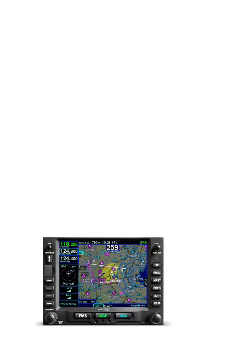
1 System Overview
This manual assumes that the pilot is appropriately licensed, is
proficient in operation of the aircraft and its equipment, and is in
compliance with all Federal Aviation Regulations (FARs).
All images contained in this manual are for reference use only,
and are subject to change.
Avidyne strongly recommends that pilots use the IFD540 system
only under VFR conditions until completely familiar with its
operation and use.
Boxed areas marked as NOTE within this manual identify certain
situations or areas of operation having heightened safety
implications. While it is important for the operator to be familiar
with all of the information in the manual, it is essential to the safe
use of the IFD540 that pilots give careful attention to the material
contained within these NOTEs.
In order to avoid a diversion of attention from the task of safely
taxiing, pilots should avoid performing the described cockpit tasks
while the aircraft is in motion on the ground. It remains the pilot’s
duty to monitor the IFD for proper function upon activation and
during use.
Internal IFD540 data logs and the storage devices that record and
store data are property of Avidyne.
IFD540 Integrated Flight Display
System Overview 1-1
Page 8

INTENDED FUNCTION
The Avidyne IFD540 is a GPS-nav-com radio whose primary
function is to conduct nav-com tuning and communication, and
serve as the principal navigation sensor/system for all IFR VHF
(“VLOC”) and GPS-based navigation and instrument flying
(enroute and approach), provided it is either installed in the
“primary field of view” or is connected to an external CDI/HSI
indicator that is installed in the “primary field of view” as well as a
remote source selection annunciator.
Supplemental functions include serving as a moving-map flight
management system (FMS), and electronic charts and checklists
along with a number or timer and calculator types of utilities.
FUNCTIONAL OVERVIEW
The Avidyne IFD540 Integrated Flight Display (IFD) system
supports the following functions:
Flight Management System (FMS)
WAAS and non-WAAS GPS Navigation
VHF Radio Nav/Com (16W and 10W variants)
Moving Map
Terrain Awareness and Forward Looking Terrain
Alerting
Weather Datalink and Lightning sensor depictions
Traffic
Electronic Approach Plates
Electronic Checklists
Data Logging
Caution Advisory System (CAS)
Utilities (e.g. Schedulers, Timers, Calculators)
Multi-touch Touch screen Control
Multiple IFD Operations
1-2 System Overview
Page 9
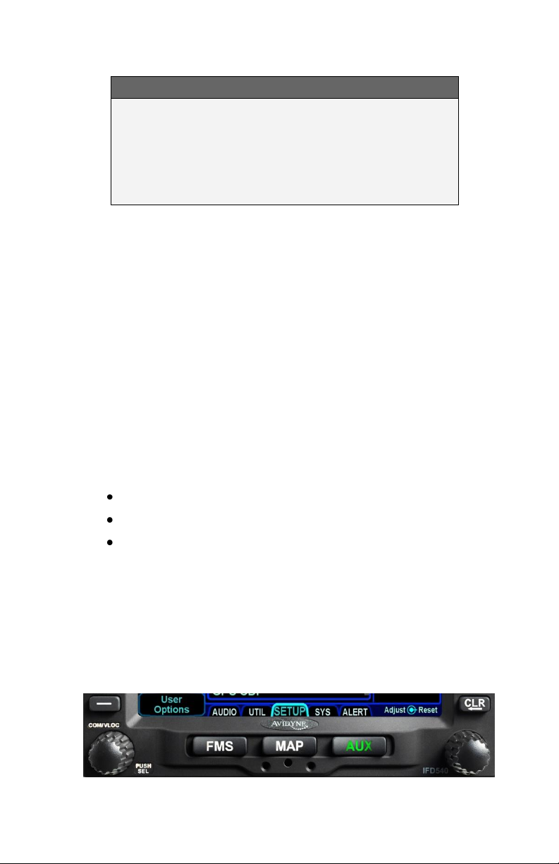
COOL FEATURE
Multi-Touch Touch Screen Control
The IFD supports multi-touch touch screen
technology meaning that features such as twofingered pinch zoom for range changing on maps
and charts is fully enabled.
The system has been designed for single-pilot IFR operation and
features a Page and Tab user interface.
Most functions revolve around the three Page Function Keys
that appear across the bottom edge of the bezel. Each of the
three functional pages has associated tabs, which contain related
data, often in different views. These functions and tabs are
covered in detail throughout this reference manual.
BASIC CONCEPTS
PAGE FUNCTION KEYS
The 3 buttons along the bottom of the IFD bezel are called Page
Function Keys. Each key is labeled by function:
FMS (Flight Management System)
MAP (Moving Map)
AUX (System Pages)
Each page has a number of associated tabs. Each Page
Function key has a left and right rocker nature to it. Select the
page of interest by pressing the middle of the Page Function Key
and navigate through the available tabs by pressing the left or
right side of the Page Function Key. Continual pressing of one
side of the function key will automatically step through the tabs.
Page Function Keys and Tabs
System Overview 1-3
Page 10
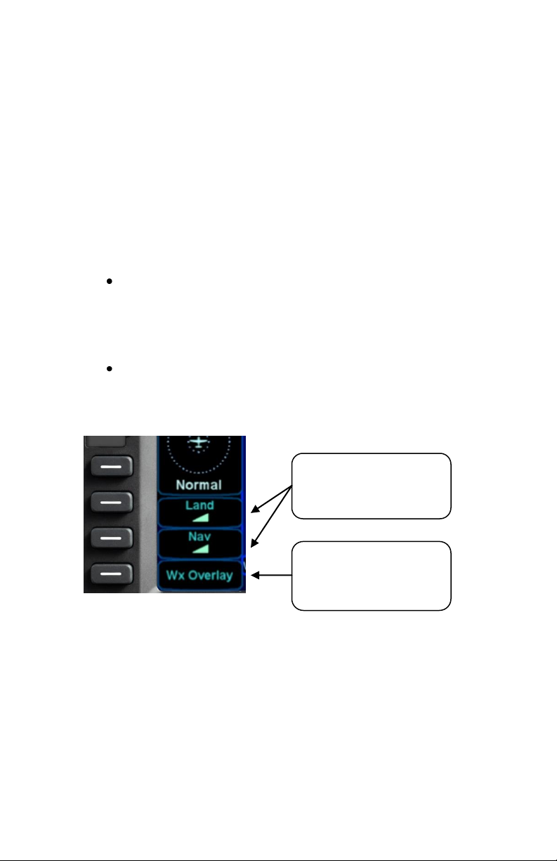
State LSKs – Push the
button or touch the label
to cycle through the list of
Action LSK – Press the
button or touch the label
to engage an action (bring
up Wx Overlay on map)
LINE SELECT KEYS
Line Select Keys, typically abbreviated to LSK in this manual,
are the buttons found along the left vertical side of the bezel.
These are different from Page Function Keys in that they also
have a label, just inside the bezel adjacent to the physical LSK
which indicates the function of the LSK. Pressing the LSK or
touching the LSK label on the display either performs the labeled
action or changes the state. For the cases where there is a list of
selectable options, browse the list by pressing the LSK.
LSK Types
State LSKs – Green button title in the first row
and a white state display in the second row
indicates a list of choices. Traverse the list in one
direction by pressing the line select key or in the
other direction by touching the label.
Action LSKs – Pressing the LSK or display label
enables the action indicated on the label.
LSK Types
RIGHT KNOB LABELING
The bottom right IFD knob is a modal knob in that its function is
context dependent and is “soft-labeled” on the display. As a
general rule, the inner and outer rings of the dual concentric knob
perform the same function – it’s just that the inner ring is “fine”
control and the outer ring is “coarse” control of that function. The
symbol used to represent the right knob is a ring with a center
dot.
1-4 System Overview
Page 11

IFD Feature/Function
Color
Page Function Keys
Green – Active;
White – Available but not
currently active.
Note: AUX can also be
Red, Yellow or Cyan if there
is an active alert as
described later in this
manual.
FMS “Fly To” Data (e.g. active leg
of flight plan, To Waypoint
datablock)
Magenta
Active Nav Data (e.g. Active Com
freq, Active Nav freq, Active Nav
Source mode)
Green
Line Select Key Labels
Light Green
Line Select Key States
White
Right Knob Label Scheme
In the example above, the outer ring scrolls through a list in a
coarse manner and the inner ring scrolls through the same list
stopping at each minor field along the way. Pushing the knob
generates a drop-down menu.
COLOR PHILOSOPHY
There are a few generalities with the use of color that are
consistent across the IFD as described in the table below:
System Overview 1-5
Page 12
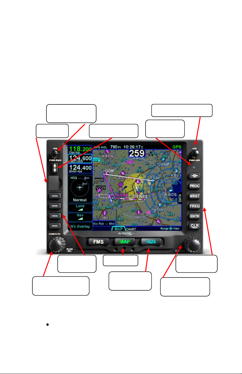
Volume / Power /
Squelch Knob
Frequency Swap
USB Port
Line Select
Keys (LSKs)
Com/Nav Manual
Tuning Knob
Page Function
Keys
Cam Latch
Context Sensitive
IFD Knob
CDI Nav Source Knob
Ambient
Light Sensor
Dedicated
Function Keys
GENERAL IFD OPERATIONS
The IFD540 Integrated Flight Display (IFD) is a touch screen
GPS-Nav-Com that has been designed to be both a retrofit GPSNav-Com or a clean install GPS-Nav-Com. As a retrofit
installation, the unit was designed to be plug-and-play compatible
with a Garmin 530/W unit.
BEZEL LAYOUT
Starting in the top left corner and working counter-clockwise
around the bezel, the IFD540 has:
Power/Volume/Squelch knob;
1-6 System Overview
Page 13

Frequency (Active Standby) Swap dedicated
button;
USB port for database updates, datalog
downloads, software updates and powering USB
devices in-flight;
Four (4) Line Select Keys (LSKs) that are page
dependent with soft key labels adjacent to each;
Dual Concentric Rotary Knob as a means of
manually tuning Com and Nav frequencies;
Three (3) Page Function keys along the bottom
(FMS, MAP, AUX);
Mechanical Cam Latch control for tray installation;
Dual Concentric Rotary Knob that is page
dependent;
Six (6) Dedicated Function Keys consisting of:
o Direct-To (“-D->”)
o Procedure (“PROC”)
o Nearest (“NRST”)
o Frequency List (“FREQ)
o Enter (“ENTR”)
o Clear (“CLR”)
Ambient Light Sensor;
CDI Nav Source knob.
System Overview 1-7
Page 14
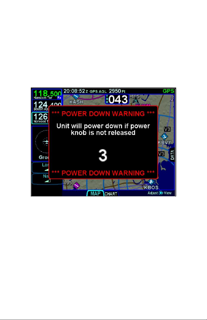
POWER CONTROL
The IFD is regulated by a pair of circuit breakers. There is also a
power control on the top left corner of the unit but the IFD will
automatically start when the aircraft bus power is applied. The
power button can be used to turn the unit off (press and hold and
watch 5 second count down expire) or to turn the unit back on if it
had been manually turned off.
Manual Power Down
After power application, the bezel keys backlighting will be turned
on. Several seconds later, the IFD display will begin to have
indications.
1-8 System Overview
Page 15
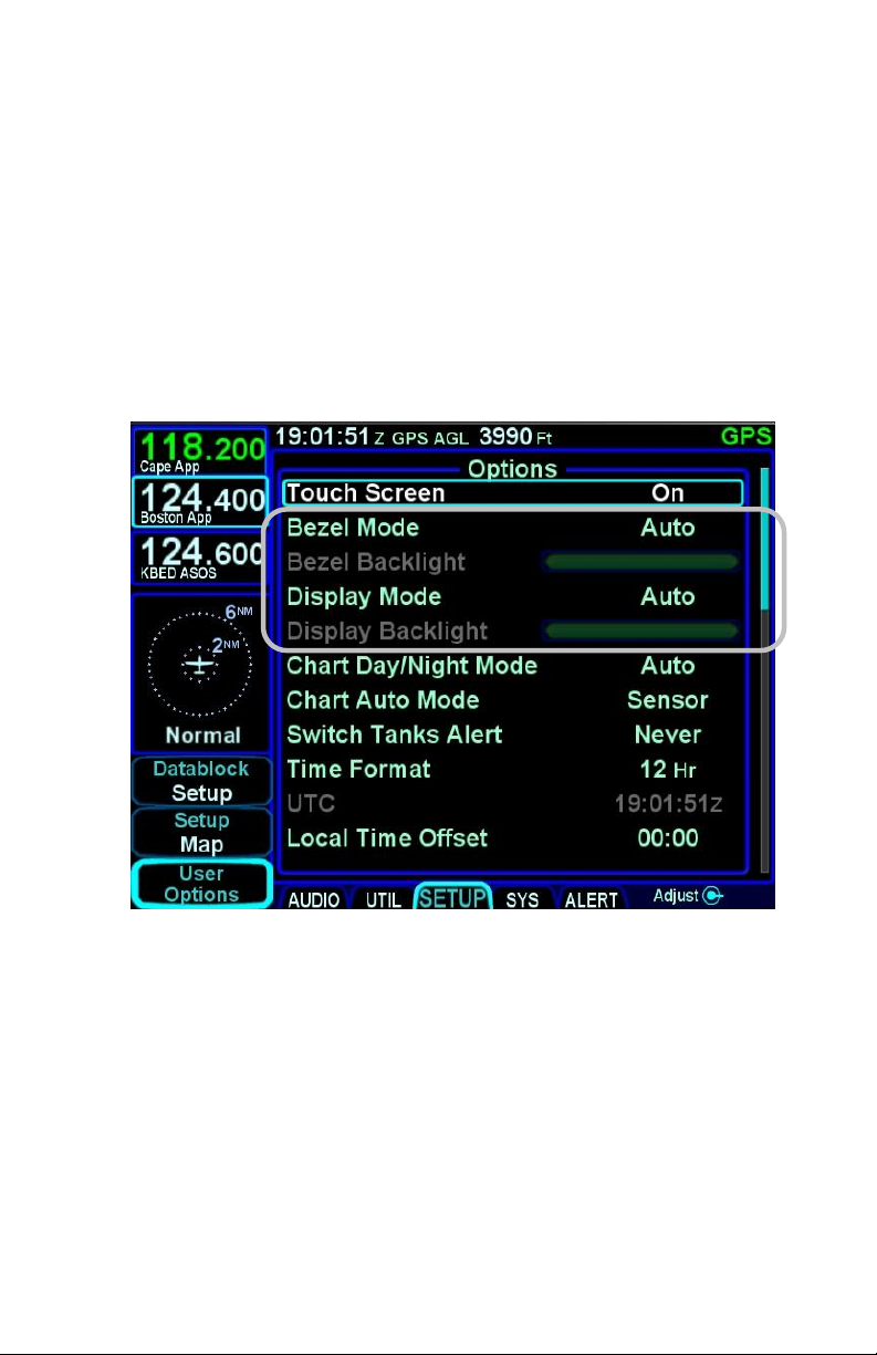
BRIGHTNESS CONTROLS
Each IFD has brightness controls to control both the bezel and
the display brightness. The user can access individual controls to
allow for either manual control of brightness, automatic control of
brightness in response to the cockpit dimming controls/rheostats
or automatic control of brightness in response to the ambient light
sensor that is embedded in the bezel. The user accessible
controls for all are on the AUX page using the User Options LSK
of the Setup tab.
Brightness Controls
Depending on how the installer configured the brightness controls
at time of installation, the “Auto” setting will typically revert to the
dimming bus setting in low ambient light conditions.
If the IFD540 appears “inoperative” or non-responsive from a
lighting perspective, check the aircraft instrument lighting rheostat
to ensure it is not set to a night position.
System Overview 1-9
Page 16

START-UP SEQUENCE
The startup sequence of the IFD is as follows:
A splash screen will be displayed during system
initialization and will be automatically removed
when the IFD is initialized. The Page Function
keys (e.g. FMS, MAP, AUX) will not be lit up while
the splash screen is present;
An agreement of the limitation of your legal rights
must be made via the bezel “ENTR” button. Note:
For the duration that the agreement page is
displayed, the IFD is activating the signals that
connect with a remote annunciator panel as well
out outputting self-test data to external devices.
Use that condition as a lamp test and external
signal check;
A software version and database currency page is
displayed IF there any expired databases.
Avidyne does not recommend operating with
expired databases but the system will allow
operation by pressing the “Proceed” followed by
the “Confirm” LSKs;
If there is a fuel flow system connected to the IFD,
then the IFD will automatically transition to the
Fuel Management Page. If the fuel flow system
does not provide fuel totalizer data, you will need
to input the fuel on board and press the “ENTR”
key. If the fuel flow system does provide fuel
totalizer data, confirm the total is correct and press
the “ENTR” key.
If there is no fuel flow system connected, then the
unit progresses directly to the FMS page and FPL
tab, in principle ready for a flight plan to be loaded
or verified;
The IFD is now ready for normal use.
The agreement page, database expiration and fuel management
entries are all skipped if the unit is powered on in-flight.
1-10 System Overview
Page 17

NOTE
Some Data May Be Delayed at Startup
Some data such as fuel flow and fuel totalizer may
experience a 5-10 second delay during post start
initialization. For those aircraft configured with fuel
totalizers, this may result in some fuel display
changes on the Fuel Mgmt tab during that period
including prompting the pilot to enter in initial fuel.
That should resolve itself within a few seconds.
Another example concerns the FMS nav database
initialization. In this case, the message “Please wait
– System Initializing” may be displayed on the FPL
tab for 10-30 seconds. Additionally, if the unit has
been exposed to extreme cold prior to start, it may
take a warm up period to achieve standard
performance.
TIPS AND TECHNIQUES
Manual Check of Database Dates
Even if the databases are all current, you can still
view the date/status of each database from the AUX
page, Database Status display as described in
Section 4 of this manual.
TIPS AND TECHNIQUES
“GPS No Position” Message Possible at Startup
If the GPS alignment takes an unusually long time
(e.g more than 2 minutes) to acquire an initial
position fix, the “GPS No Position” advisory
message will be displayed. This message will
automatically clear itself when a fix is acquired. If
the message does not remove itself by the time you
are ready to taxi, it is a clear indication that your
system has not determined its initial position and
action may be required on your part.
System Overview 1-11
Page 18

Database Status
Message
Color
In Effect
Valid Thru <Month,
Day, Year >
Light Green
Has Expired
Expired <Month,
Day, Year>
Yellow
Not Yet Effective
Effective <Month,
Day, Year>
Yellow
Charts Issue Date
Between 14 and 21
Days Old (i.e. up to
a week out of date)
Update Available
<Next Cycle Date>
Light Green
Charts Issue Date
Older Than 21 Days
(i.e. more than a
week out of date)
Update Required
<Date of
Expiration>
Yellow
Invalid
<Type> Database
Invalid
Yellow
DATABASE CURRENCY STATES
The following table describes the various database currency
states that may be observed at startup:
NOTE
Use of Not Yet Effective Data
If attempting to use not-yet-effective data (e.g.
charts or nav), it is the responsibility of the pilot in
command to verify there are no differences between
the current data and the not-yet-effective data
before it is permissible to use the not-yet-effective
data.
1-12 System Overview
Page 19
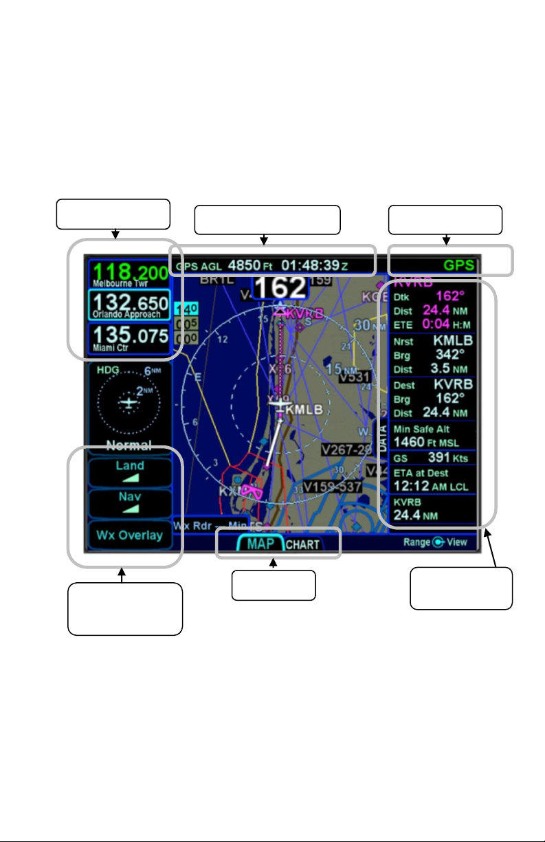
Top strip datablock area
Nav Source Label
Configurable
Data Strip
Page Tabs
Context sensitive
Line Select Keys
(LSKs)
Com/Nav Blocks
PAGE LAYOUT AND FORMATS
The left column (radio frequencies and context-sensitive line
select keys), top data strip and nav source knob indication, and
bottom edge set of page tabs are always displayed on every
page.
Page Layout
Use a combination of the page function keys (FMS, MAP, AUX)
and the associated tabs, to change the contents of the rest of the
display.
Each page has a number of associated tabs. Each Page Function
key has a left and right rocker nature to it. Select the page of
interest by pressing the middle of the Page Function key and
System Overview 1-13
Page 20
navigate through the available tabs by pressing the left or right
side of the Page Function key. The desired tab can also be
touched to directly jump to that tab. The last tab selected on any
given page is retained in memory and will be displayed when you
return to that page.
COOL FEATURE
Split Pages
The split pages where extra data can be displayed
along the right edge can be handy pages in all
phases of flight.
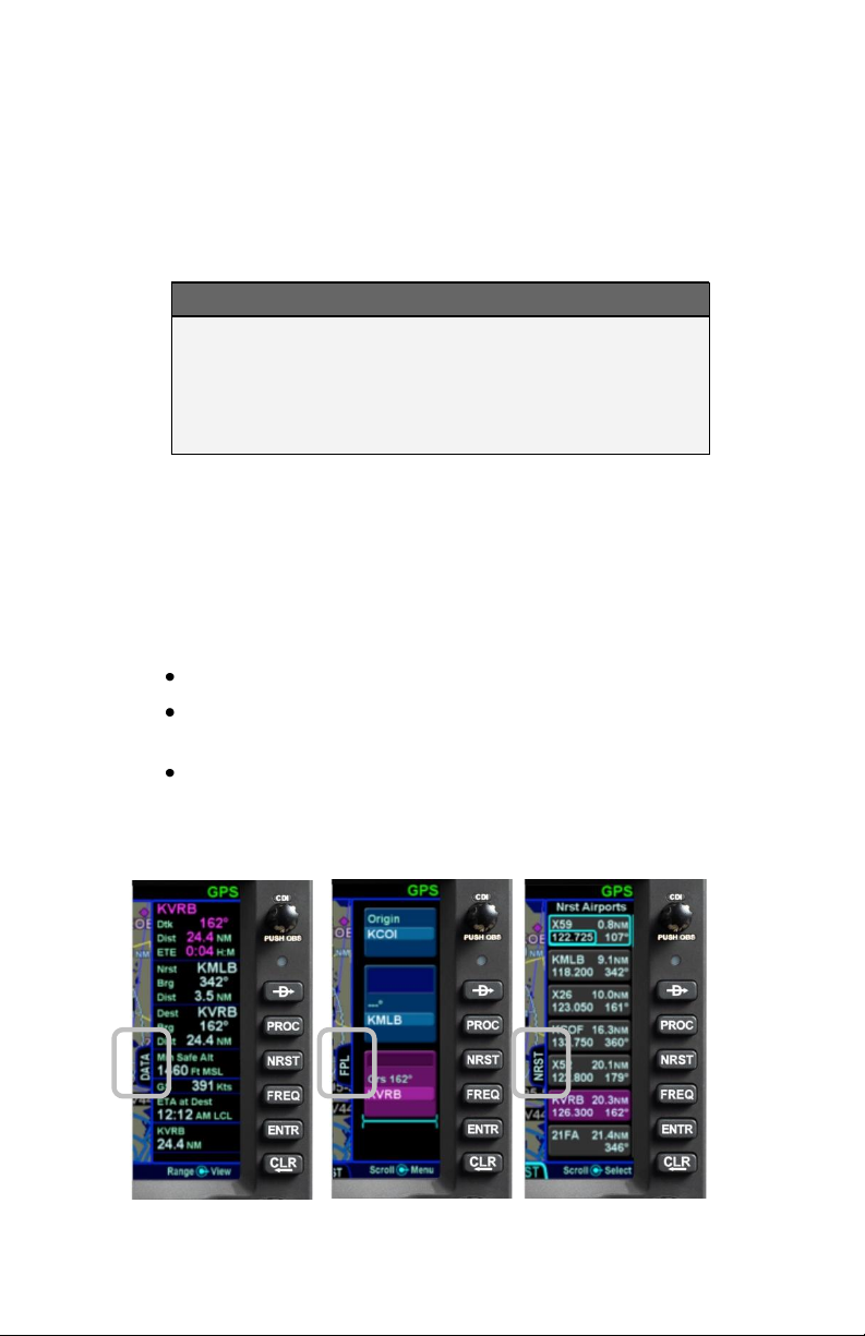
Some pages can display a data strip along the right edge of the
display. The FPL tab and NRST tab on the FMS page and the
Map tab on the MAP page are prime examples. In the cases
where this is available, a labeled side tab is displayed. That extra
data strip can be pulled out for display or pushed back in for
hiding by using any of the following methods:
Touch the side tab (shown in gray boxes below);
Use a left or right swiping motion on the tab as
required to pull it out or push it back;
Press and momentarily hold the left or right side of
the Page Function key as required to uncover or
hide the extra data strip.
Map-Data Split Map-FPL Split Map-NRST Split
1-14 System Overview
Page 21

COM-NAV
The VHF radio consists of a Com radio that covers the frequency
band from 118.0 MHz to 136.990 MHz and a Nav radio that
covers the frequency band from 108.0 MHz to 117.95 MHz. Both
25 kHz and 8.33 kHz spacing is supported. The radio can be
configured as a 16 watt or 10 watt transmitter at the factory prior
to shipping.
Display
The active com frequency (the frequency that the radio will
transmit on when the Push-To-Talk button is pressed) is
displayed in green and the standbys (there can be more than one
standby frequency) are displayed in white.
Display of the frequencies can be formatted in several ways via
the “User Options” and “Datablock Setup” LSKs of the SETUP tab
on the AUX page (see the Datablock Setup description in Section
4 for more details). The default display format is two com
frequencies (active and #1 standby) above two nav frequencies
(active and #1 standby). A custom display format can be set up
to display the active com and up to four standby com frequencies.
The frequency that will be swapped into the active frequency
when the bezel Frequency Swap button is pressed is called the
“# 1 Standby”. For example, in the case where the user has set
up 4 com slots to be displayed, any one of slots 2, 3 or 4 can be
selected to be the “#1 Standby” simply by touching the slot. In
every case, the “#1 Standby” slot is visually indicated by a cyan
outline.
System Overview 1-15
Page 22
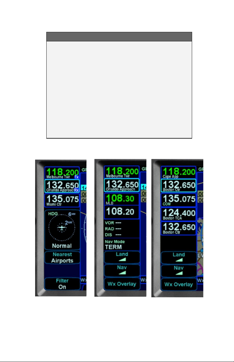
COOL FEATURE
Multiple Standby Frequencies
The com (or nav) frequencies can be formatted to
act as a type of quick directory when set up ahead
of time. This can be handy in local area operations
when just a few standard frequencies are expected
to be used for a flight – for example ATIS, Ground,
and Tower frequencies can be entered in three com
slots for quick swapping into the active channel.
Touch the frequency slot that you want to be the #1
Standby at any given time and then when the bezel
Frequency Swap button is pressed, that slot is what
is swapped with the Active channel.
Multiple Frequency Formats
1-16 System Overview
Page 23
COOL FEATURE
Decoded Agency Identifier
The agency (e.g. Clearance Delivery, Ground,
Tower, Approach, etc) for the Active and each
displayed Standby com frequency are displayed in
each com frequency slot. This is a handy reminder
of the agency to which you have tuned in each slot.
Similarly, if the frequency displayed is a nav
frequency, then the Morse code decoded identifier
will be displayed and will stay displayed for as long
as the IFD can decode the Morse code, which
serves as a usable means to Tune-Identify-Monitor.
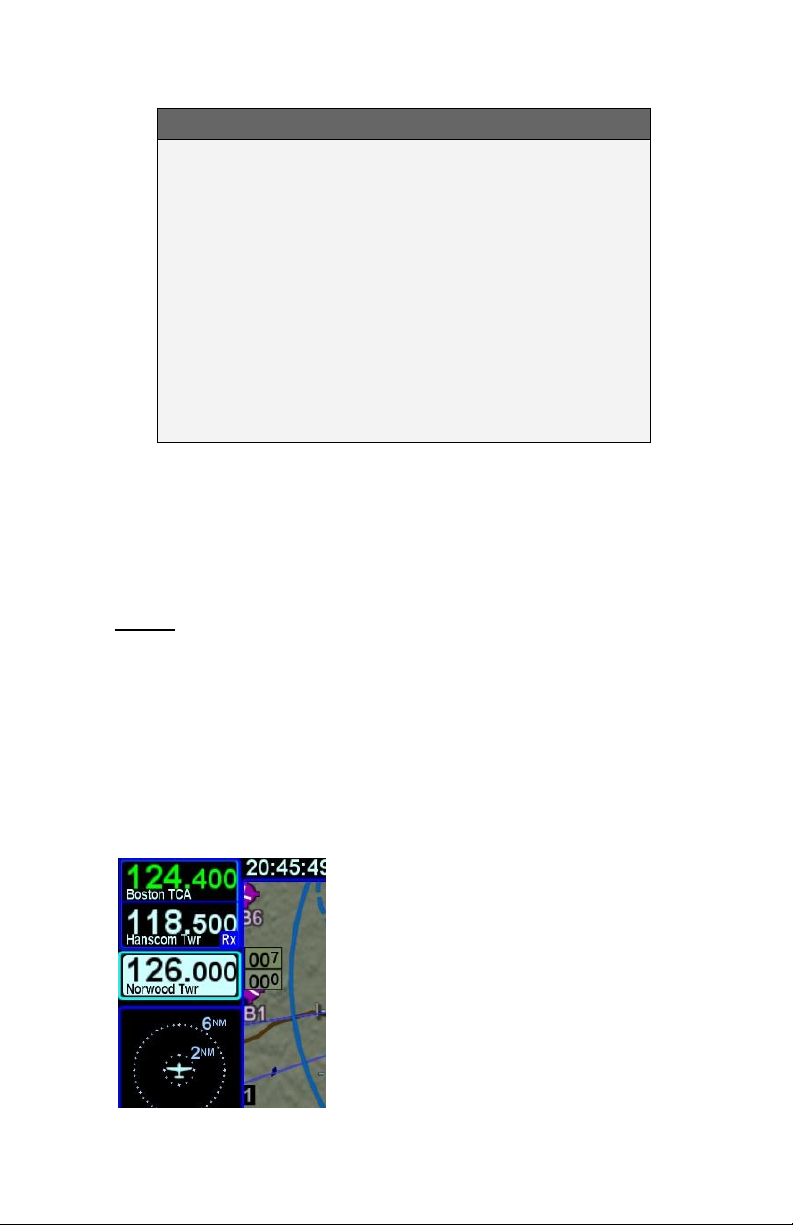
If a slot is receiving a voice transmission, a “RX” indication will be
displayed along the right edge of the given com slot.
When the active frequency is transmitting, a “TX” indication will
be displayed along the right edge of the Active com slot.
Tuning
Tuning can be accomplished through several methods.
Whichever frequency slot has been selected as the #1 Standby
can be manually tuned by twisting the bottom left knob on the
bezel. The outer ring changes the digits to the left of the decimal
point and the inner ring changes the digits to the right of the
decimal point. The slot being tuned this way is highlighted in
reverse video as depicted in the 126.000 example below.
Manual Com/Nav Tuning Reverse Video Depiction
System Overview 1-17
Page 24
A second way to manually tune a frequency is to touch the Active
or Standby frequency slot and when a virtual keyboard is
displayed, type the desired frequency into the numeric keypad
and press the Enter (“Enter” on the virtual keypad or “ENTR” on
the bezel) button. The numeric keypad will time out and be
removed after 10 seconds of inactivity.
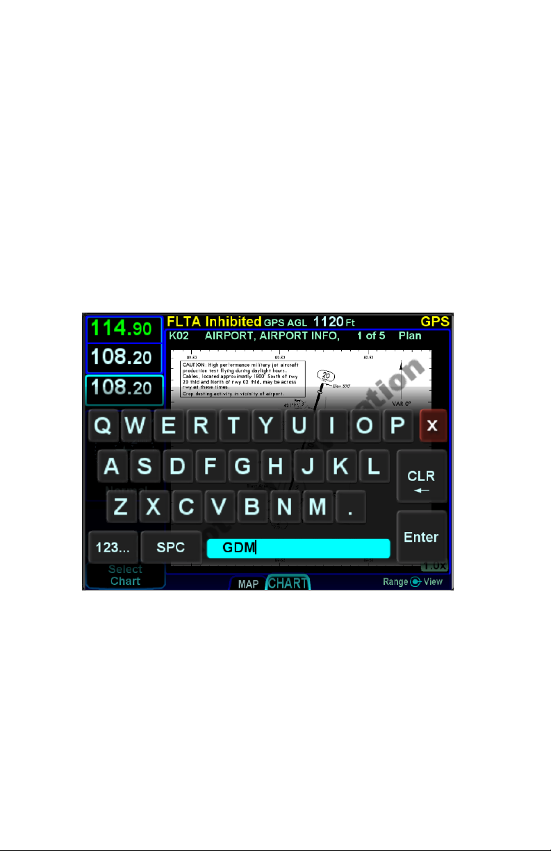
Another way to manually tune a frequency (only useful for tuning
VOR Nav frequencies) is to type the identifier of the desired
frequency (e.g. “GDM” for the Gardner VOR) via the
alphanumeric virtual keypad. An automatic, geographic-based
prediction algorithm (“geofill”) is running such that the most likely
VOR station is filled in based on your geographic position.
Manual Entry of VOR Identifier
A more automated way to tune a com frequency is to press the
“FREQ” button along the right edge of the bezel. This will present
a list of likely frequencies and that list can be scrolled via an
up/down motion with touch or via twisting the right hand knob. If
touch was used, double tap on the row that you want to put into
the #1 Standby. If the knob was used to scroll through the list,
push the knob in to put the frequency into the #1 Standby slot.
Frequencies can also be nominated to be put into the #1 Standby
from other pages on the IFD540 such as the INFO or NRST Tab
on the FMS page.
1-18 System Overview
Page 25
Switching Between Com and Nav
To access the Nav frequencies for display or editing, push in the
lower left knob to toggle between Com frequencies and Nav
frequencies. The displayed set of frequencies will always time
out back to com frequencies following 20 seconds of inactivity on
the Nav frequency display.
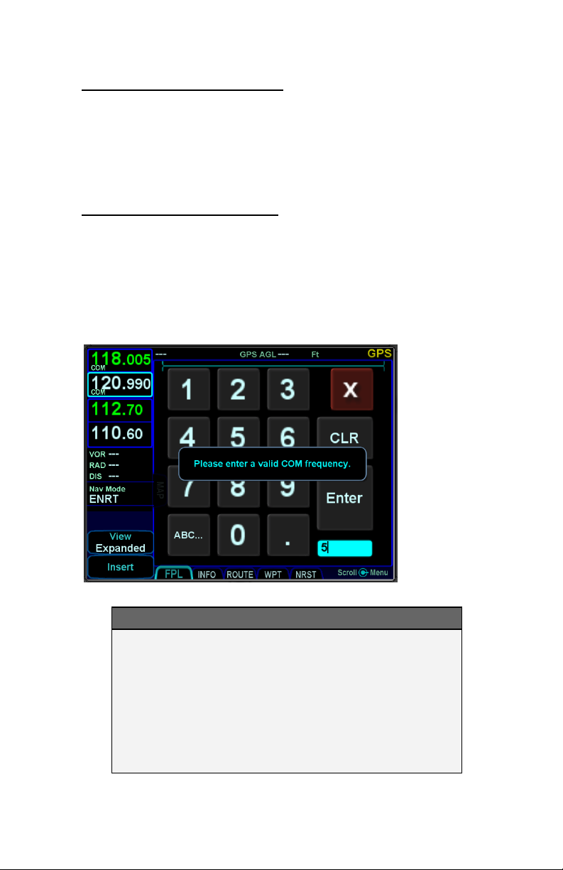
Invalid Frequency Entry Attempt
Attempting to type an invalid frequency (e.g. typing a nav freq in a
com slot) will produce a temporary error message indicating the
mistake. This message is unavailable in dual IFD installations
that have Keyboard Convenience mode (described later) turned
on.
Notification of Invalid Frequency Entry Attempt
COOL FEATURE
Shortcuts to Com Tuning
Shortcuts are provided to aid speed and ease of
manually entering a com frequency in the IFD. For
example, there is no need to type the leading “1” for
frequencies, the decimal point, trailing zeros or the
thousandth digit. For 121.700, type “217” and press
Enter.
System Overview 1-19
Page 26
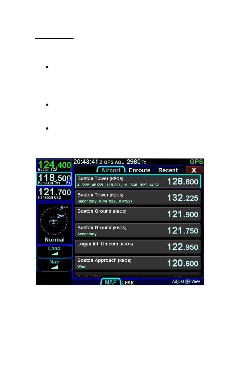
Frequency List
The “FREQ” function key along the right edge of the bezel has
three tabs along the top edge of the page:
Airport – the most logical com frequencies (e.g.
ATIS, ASOS, AWOS, CTAF, Tower, Ground,
Clearance Delivery, etc) associated with the origin
airport and then when airborne and more than
5nm from the origin, the destination airport;
Enroute – the most likely enroute ARTCC and
other enroute com frequencies (e.g. FSS) for the
current geographic position;
Recent – a running list of the com frequencies that
had been selected for the Active frequency slot
within a given power cycle.
Freq List Page
Each additional press of the “FREQ” function key will cycle to the
next top tab. The top tabs can also be touched to activate that
specific list. The tabs only populate when there is a GPS position.
When a desired frequency has been located in the list, it can be
placed into the #1 Standby slot by either double tapping it via
touch or pushing the bottom right dual concentric push knob.
1-20 System Overview
Page 27

Emergency Com Frequency
121.5 kHz can be quickly put into the Active com slot by pressing
and holding the bezel frequency swap button for approximately 3
seconds.
Stuck Mic
If the IFD determines that there is a stuck mic situation (defined
as 30 seconds or more of continuous transmission), a “Stuck Mic”
CAS message (Blue Advisory message) will be displayed.
Remote Tuning Control and Frequency Swapping
The IFD supports a host of remote tuning and frequency
swapping capability.
A “Com Presets” LSK will be present on the AUDIO tab of the
AUX page and up to 16 com frequencies can be preset. Some
aircraft installations will also include a dedicated Remote Tuning
control (e.g. dedicated button on the yoke) which will step through
the list of preset com frequencies loading each into the #1
Standby slot. Each time that control is activated, the display will
pop up a dialog box next to the #1 Standby slot indicating which
item in the preset com list has been selected. In addition, a cyan
arrowhead will be displayed next to the currently selected
frequency on the Com Preset page.
Another capability that can be added during installation is a
remote com frequency swapping function that, when activated,
performs the same action as pressing the bezel Frequency Swap
button. In this case, your hands do not need to leave the controls
to command a frequency swap. Typical installations that support
this feature include a dedicated Frequency Swap control (e.g.
dedicated button on the yoke). Pressing and holding the
dedicated Frequency Swap control button for approximately 3
seconds will insert 121.5 kHz into the Active com slot.
Other remote tuning and frequency swapping capability is present
when dedicated third-party radio control display units are wired
into the aircraft. Usually in these cases, when the radio control
display unit is active, the Active and #1 Standby frequencies are
only displayed on that external control display unit and not on the
IFD, even though the actual radio is still housed inside the IFD.
System Overview 1-21
Page 28
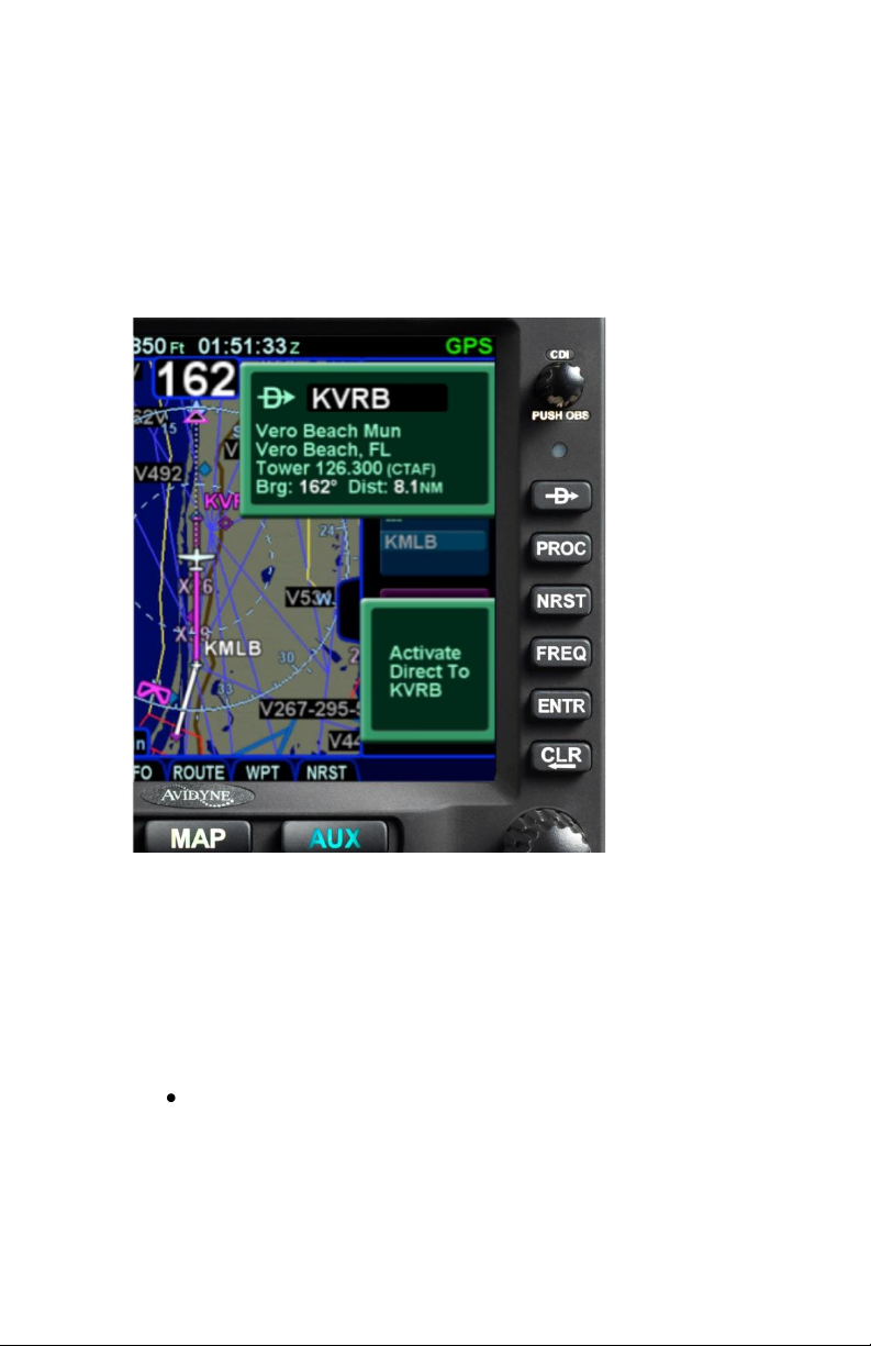
DIRECT-TO OPERATIONS
A dedicated Direct-To function key is located along the right edge
of the IFD bezel. Pressing that button from any page will display
a green Direct-To dialog box that will be pre-populated with a
logical waypoint.
Direct-To Dialog and Confirmation Dialog Boxes
If that pre-populated waypoint is the desired waypoint, press the
“ENTR” function key along the right edge of the bezel twice
(Direct-To, Enter, Enter) or touch the Activate dialog box that
pops up on the display to accept.
If a different waypoint is desired, there are a number of ways in
which the proper waypoint can be entered in that Direct-To dialog
box:
Twist the outer ring of the bottom right IFD knob to scroll
up/down through a flight plan list that re-populates the
waypoint in the dialog box from the active FMS flight plan
(Note that the Missed Approach must be activated to use
this technique for points in the published missed approach).
1-22 System Overview
Page 29

When the desired waypoint is displayed, press the knob in
to accept;
Touch the waypoint field in the pop-up green Direct-To
dialog box to generate a virtual keyboard and type in the
desired waypoint name. When the desired waypoint is
displayed, press Enter on the keypad or bezel to accept;
Twist the inner ring of the lower right IFD knob while the
pop-up green Direct-To dialog box is displayed to go into
edit mode. The inner ring changes the character and the
outer ring changes the cursor position in the waypoint name
field. It may not be necessary to fill in all letters of the
waypoint name since they will auto-fill. When the desired
waypoint is displayed, press Enter on the keypad or bezel
to accept.
FUNCTION KEYS
In addition to the Direct-To and Frequency List function keys that
have already been described, the IFD has a Nearest (“NRST”)
function key and an Enter (“ENTR”) function key and a Clear
(“CLR”) function key that perform the following functions:
Nearest – Simultaneously jumps to a Nearest
page (if not already there) and presents a list of
the nearest airports to your present position. Each
additional press of the “NRST” function key
changes the nearest list to another category as
defined in the list below:
o Nearest Airports
o Nearest Airports to Destination
o Nearest VORs
o Nearest NDBs
o Nearest Intersections
o Nearest ARTCCs
o Nearest FSS
o Nearest Airspace
o Nearest User Waypoints
System Overview 1-23
Page 30
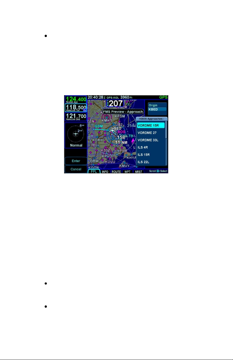
Procedure – The “PROC” function key acts as a
shortcut for attaching a published arrival or
approach procedure to a waypoint in your flight
plan. It can be used at any time. The first press of
the function key results in the IFD displaying the
FPL tab of the FMS page with the Approach field
of the next destination after the active leg
highlighted in reverse video and a drop down list
of available published approaches listed.
Pressing it a 2nd time will step the reverse video
over the Arrival field and present a drop down box
of available published arrivals. Each subsequent
press of the “PROC” key will step through all
following destination airfield approaches and
arrivals in the flight plan and wrap back around to
the top of the flight plan. When the drop down box
appears over the intended data field, twist the
bottom right IFD knob to scroll up or down the list
until the desired procedure is highlighted and then
push the knob in to add that procedure to the flight
plan. If there is no flight plan, pressing the
“PROC” key will present the FPL tab with an insert
cursor at the top of the page but will not present
any procedures.
Enter – The use can vary slightly depending on
the scenario, but “ENTR” is always related to the
Enter/Accept/Confirm use;
Clear – The use can vary slightly depending on
the scenario, but ”CLR” is always related to
Clear/Backspace/CAS Message Clear use.
1-24 System Overview
Page 31

TOUCH SCREEN
The IFD uses a capacitive touch screen technology that allows
multi-touch operation (e.g. two-fingered pinch zoom). Many types
of gloves can be used during touch screen operations.
The IFD employs a “hybrid touch” design in that virtually every
interaction can be accomplished either through bezel controls or
touch. This allows for flexibility in operational use. Some
features or functions naturally lend themselves to being easier to
accomplish through touch (e.g. map panning) and some are
naturally easier to do via physical bezel controls (e.g. changing
pages or using dedicated functions like the Freq List). We have
found that individual usage patterns tend to emerge and personal
preference has a strong influence as well. Perhaps most
importantly, hybrid touch is useful during turbulent or bumpy flight
conditions where it is often very difficult to precisely and reliably
touch the desired point on the display. Having a physical bezel
control provides an “anchor point or control” to hold on to and
exercise the intended action.
TIPS AND TECHNIQUES
User Control to Turn Touch Off
The “User Options” LSK on the SETUP tab of the
AUX page provides a touch screen on/off selection
capability. This can come in handy in excessively
bumpy flight conditions when even attempting to
use physical bezel controls can result in inadvertent
touching of the screen and potentially causing
unintentional display changes. The on/off setting
will persist across power cycles.
Touch zone targets have been intentionally oversized wherever
possible to aid in accurate touch screen behavior.
As noted above, virtually every feature or function of the IFD can
be accomplished either by touch or by physical bezel control.
The following table identifies the exceptions to that rule:
System Overview 1-25
Page 32
Bezel-only Control Input
Functions
Touch screen-only Control
Input Functions
Selecting page function keys
(e.g. changing the “major”
pages of FMS, MAP, AUX)
Map panning
Power on/off
Graphical Flight Planning
(“Rubber banding”)
Changing the Primary Nav
Source
Calling up a map page info box
Starting the Frequency List
Selecting a #2 or #3 standby
frequency for swapping into the
active frequency slot
Frequency Swap
---
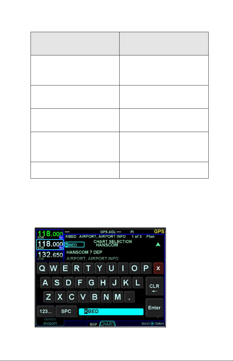
When editing data (e.g. FMS waypoint data or nav/com
frequencies) using touch, virtual keyboards are displayed on the
IFD. There are two formats – a numeric keyboard and an alpha
keyboard with a means to switch back and forth between formats.
Virtual Alpha Keyboard
1-26 System Overview
Page 33
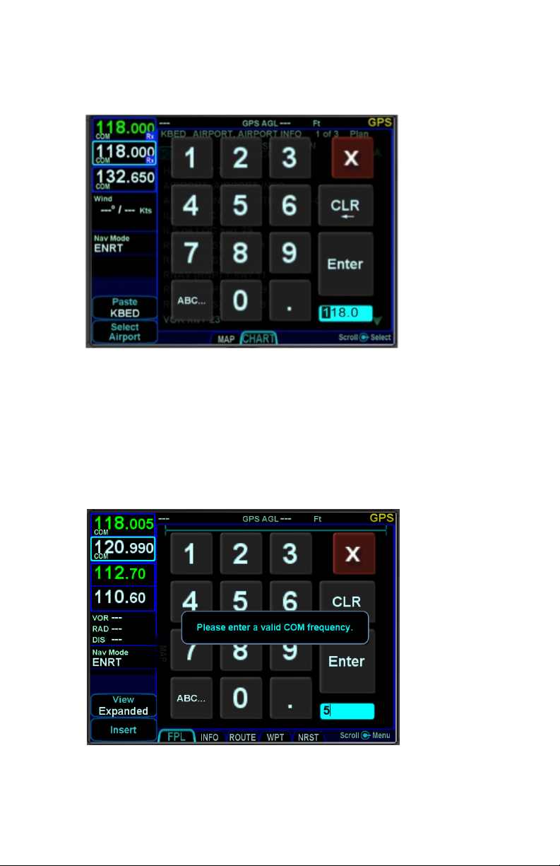
Virtual Numeric Keyboard
Each keyboard has a scratchpad in the lower right corner. The
scratchpad is a free text field for data entry with some data entry
validity logic applied to the data that is trying to be entered. For
example, when trying to type in an invalid frequency, the com
tuning application will immediately sense that entry to be invalid
and present an alert box stating the entry is invalid. Validity logic
is not applied on cross-side keyboards in dual IFD installations.
Invalid Keyboard Entry Alert
System Overview 1-27
Page 34

TIPS AND TECHNIQUES
Optimal Touch Performance
To maximize touch performance, the more surface
area of a finger that can make contact with the
glass, the better. Try to avoid using just fingernail
contact or just the tip of a finger. Increased
pressure on the glass by your finger should not
have any positive effect. Many types of gloves will
work (see “Use of Gloves” section in the back of this
manual), but performance will likely be degraded.
DUAL IFD OPERATONS
Some installations may involve two IFDs (e.g. IFD540-IFD540,
IFD540-IFD440, IFD440-IFD440) that can work in a more
integrated fashion.
Method of Data Share (Dual IFD Operations)
Dual IFDs will be connected via the Byteflight digital Databus.
While any of the com ports can be configured for the dual IFD
“CrossSync” communication, it is generally recommended that
Com 3 be used to stay consistent with the vast majority of fielded
GNS530/430 systems that the IFD will be replacing. In those
cases, Com 3 is already wired for box-to-box communication and
that connection is used for dual IFD connections with no further
work.
Keyboard Convenience Mode (Dual IFD Operations)
When Keyboard Convenience mode is enabled via the “User
Options” LSK of the SETUP tab on the AUX page, the second
IFD will automatically present a virtual keyboard when the other
IFD is in a mode where data is being entered or edited. In other
words, if Keyboard Convenience mode is turned on, a virtual
keyboard will be displayed on the “other” IFD at all the same
times as if the aircraft were configured for a single IFD and a
keyboard is displayed on that unit.
1-28 System Overview
Page 35

Shared Data (Dual IFD Operations)
The following list of data will be shared between two IFDs if
properly configured for data sharing:
Enables the integration of the Caution Alerting
System (CAS) to allow a single acknowledgement
of any of the Global messages to be removed from
both units by acknowledging them on either unit;
Enables flight plan synchronization, including
modification of the flight plan to be reflected on
both IFDs (this does allow for flight plan/procedure
preview on the second IFD);
Enables stored routes to be synchronized across
both IFDs (this does allow for route preview on the
second IFD);
Enables fuel planning (e.g. initial fuel entry) to be
synchronized across both IFDs;
Enables user waypoints to be synchronized across
both IFDs;
Enables sensor settings and data (traffic, datalink,
lightning, air data, etc) to be shared across both
IFDs.
NOTE
Full Data Sharing Requires Consistent WAAS
For complete data sharing between dual IFDs, both
units will need to have the same WAAS antenna
configuration – either both are WAAS or both are
non-WAAS. If one IFD is set up with a WAAS
antenna and one is set up with a non-WAAS
antenna, then the FMS-related data (flight plans,
waypoints, routes) will not be shared between IFDs.
System Overview 1-29
Page 36

Independent Data (Dual IFD Operations)
The following list of data will never be shared between two IFDs
no matter how they are configured:
IFD page and tab selection;
Map view, range, declutter, and overlay settings;
Chart extent box depiction on map;
Nav Source selection;
Com/Nav settings (e.g. 8.33 vs 25 kHz spacing);
Com/Nav frequency selections (therefore no
cross-side tuning or display);
Nav deviation data (therefore no navigation
miscompare alerts are provided);
Local CAS alerts;
Datablock configuration;
Chart displayed;
Electronic Checklists data and state;
Calculators and Utilities data.
.
NOTE
Data Sharing Tolerates Inconsistent Databases
While Avidyne strongly recommends the databases
on each IFD be kept up-to-date and on the same
cycle, data sharing between IFDs as defined above
in “Data Sharing (Dual IFD Operations)” is not
disabled when different data cycles are present on
the two IFDs.
1-30 System Overview
Page 37

TIPS AND TECHNIQUES
Maximize Your Map Configurations
Because you can individually configure each IFD
Map overlay, a common technique is to set up one
IFD map overlay to display Datalink weather and the
other to display sensor (e.g. Lightning) weather.
Similarly, you can display METAR flags on one IFD
and winds aloft on the 2nd IFD. Likewise, you can
display FLTA and TA on one IFD and turn them off
on the other IFD.
Avidyne would love to hear from you about your dual IFD
techniques at www.avidynelive.com; post them in the
IFD540/440 Touch Screen GPS/NAV/COM section.
WAAS VS NON-WAAS OPERATIONS
The IFD supports both WAAS and non-WAAS operations. In
each case, the IFD is still considered a “/G” system for flight plan
filing purposes.
When configured to be connected to an approved WAAS antenna
at installation, the IFD serves as a fully-certified WAAS GPS
navigator. Published WAAS procedures will be available and
presented in the various drop-down list choices in the FMS and
WAAS glideslopes will be displayed, when appropriate.
When configured to be connected to a non-WAAS antenna or a
non-approved WAAS antenna at installation, the IFD will not
provide any WAAS functionality. For example, WAAS
approaches such as LPVs will not be presented as an available
choice within the FMS.
For dual IFD installations in which one IFD is WAAS capable and
the other IFD is non-WAAS capable (a perfectly acceptable
combination under the STC), there are some limitations on the
nature of data sharing between the IFDs. In this case, FMSrelated data is not shared between the IFDs (e.g. flight plans,
stored routes and user waypoints).
System Overview 1-31
Page 38

INTERACTION WITH EXTERNAL DEVICES
Each IFD is capable of communicating with several hundred third-
party devices. Reference the Installation Manual for a complete
list of devices supported and any hardware/software baseline
restrictions or view the supported device list at
http://www.avidyne.com/products/ifd540/ifd-interfaces.asp
As a condition for certification, the IFD is approved for integration
with all equipment the GNS 530 is approved for, plus the IFD is
approved for integration with additional equipment beyond those
authorized for use with the GNS system.
BEFORE TAKEOFF TECHNIQUES
Set up the flight plan per your plans or the assigned ATC IFR
clearance. If multiple pilots share the airplane, be sure to check
User Options and datablock selections to ensure set up for your
personal preferences.
Avidyne recommends creating and using the Checklist utility and
including a Before Takeoff checklist that meets your personal
needs.
TIPS AND TECHNIEQUES
Avoid The Use of Polarized Sunglasses
Avidyne recommends avoiding using polarized
sunglasses when using the IFD due to likely
washing out of colors and apparent dimming.
1-32 System Overview
Page 39
2 FMS Pages
The Flight Management System (FMS) pages are where flight
plans are created, modified, stored and deleted. Ground
operations are the ideal time to enter the intended flight plan into
the FMS.
FPL (FLIGHT PLAN) TAB
FMS BASIC CONCEPTS
For properly configured dual IFD installations, enter your plan into
only one of the IFDs and the data is automatically shared
between them.
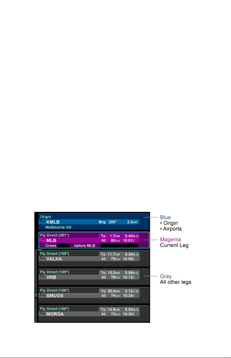
Each leg of a flight plan has its own color-coded background
designed to make the overall flight plan easier to read at a
glance. Each flight plan can consist of up to 128 legs.
The origin and all airport waypoints are depicted with a blue
background. The active leg of the flight plan is always depicted
with a magenta background. All other legs of a flight plan are
depicted with a gray background.
Flight Plan Detail
FMS Pages 2-1
Page 40
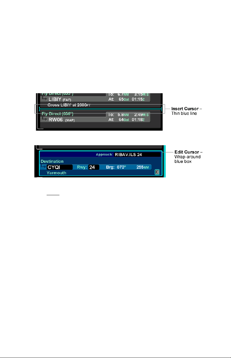
There are two types of cursors – an insert cursor and an edit
cursor. Rotate the “FMS” knob in the lower right corner of the IFD
to see the visual difference. The insert cursor will appear as a thin
blue horizontal line that appears between flight plan legs. This
allows you to insert new legs. The edit cursor appears as a wraparound blue box that encircles the entire leg and allows you to
edit an existing leg.
Insert Cursor
Edit Cursor
Individual fields within a leg can be edited by rotating the bottom
right inner IFD knob that highlights each editable field within the
flight plan. When the desired field is highlighted with reverse
video, push the knob to get into edit mode. Turn the knob to edit
the value or type via the keyboard, then push the knob again to
exit edit mode.
Using a combination of the push and rotation actions of the knob,
along with the dropdown boxes (explained below), an entire flight
plan can be entered within seconds.
CREATING A NEW FLIGHT PLAN
The first time the “Flight Plan” tab of the FMS page is accessed
following power-on, an empty flight plan page is presented with
the origin waypoint pre-populated. The origin will be the closest
airport to the current GPS position, or the airport from the
previous power down if GPS position has not locked on yet.
In almost every case, your hand can stay on the bottom right IFD
knob. Through a combination of pushes and turns, you can enter
the entire flight plan.
2-2 FMS Pages
Page 41
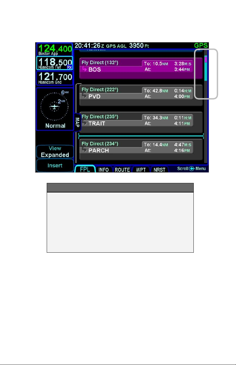
Flight Plan and Scroll Bar
COOL FEATURE
Geofill™ is a geographic-based prediction
algorithm that significantly reduces the number of
pilot actions for entering waypoints. Usually after the
first character entry, the system uses existing
characters to determine the closest, and most likely,
waypoint based on your geographic position or
existing flight plan.
If a flight plan has more legs than can be displayed on a single
page, a scroll bar is presented along the right edge of the flight
plan. It indicates where the viewable window is with respect to the
entire flight plan as well as where the active leg in the flight plan
is. In the image above, the magenta vertical rectangle in the scroll
bar indicates the active leg is just below the origin. There are a
number of flight plan legs out of sight below the bottom of the
display.
FMS Pages 2-3
Page 42
COOL FEATURE
Airways and Flight Plan Creation
The FMS can use published airways in its database
to quickly build long flight plans with few keystrokes.
When a flight plan waypoint is a valid airway entry
or exit point, the list of available airways is
presented in a drop down box. The list is quickly
scrolled to the desired exit point and then all
intermediate intersections along that airway are
automatically populated into the flight plan.
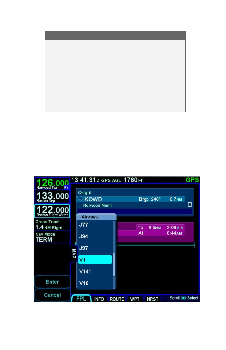
The pictures below are an example of the airway drop down box
that is displayed when building a flight plan and then the exit point
choices once the airway is chosen. Use the bottom right IFD
knob to scroll the list for the desired airway and exit point off the
airway. The exit list is presented in the order by which the
intersections will be reached, not in alphabetical order.
Airway Drop Down Box
2-4 FMS Pages
Page 43
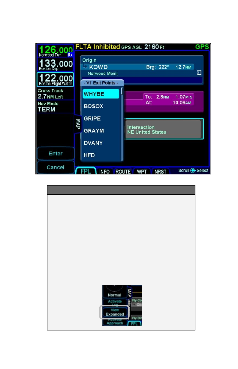
Airway Exit Points
TIPS AND TECHNIQUES
Expanding and Compacting the Flight Plan The
“Flight Plan” tab of the FMS page provides a means
to show every leg of the flight plan (“Expanded”) or
an abbreviated version of the flight plan (“Compact”)
via the “View” LSK. The compact view hides all
intermediate legs of an airway between the entry
and exit point. It also hides intermediate legs of
published departures, arrivals and approaches such
as step down fixes. The active procedure or airway
is always expanded.
FMS Pages 2-5
Page 44
SELECTING A DEPARTURE
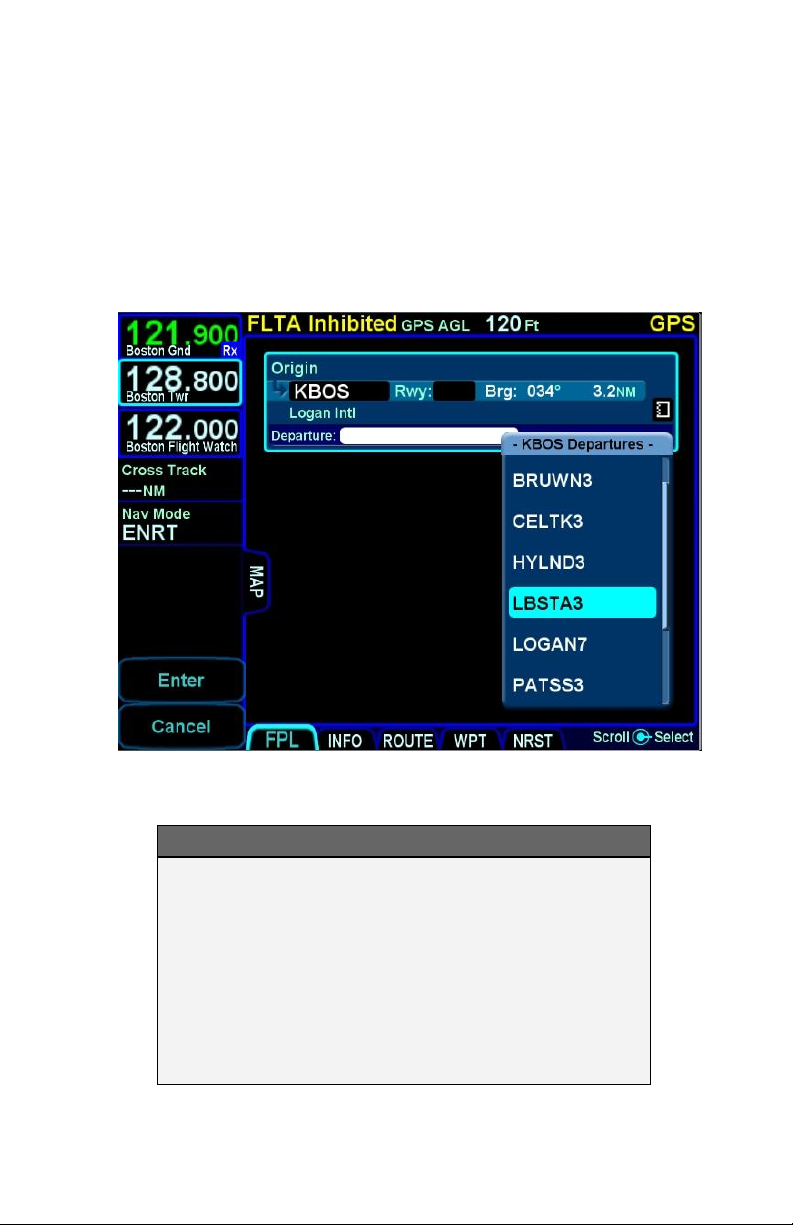
If a published departure exists for the origin/departure airfield,
then a drop down list of available departure procedures can be
displayed by using the inner ring of the bottom right IFD knob to
highlight the departure procedure window for that origin/departure
airfield and pushing in that knob.
Departure Procedure Drop Down List
TIPS AND TECHNIQUES
Vector Standard Instrument Departure (SID)
Vector (or Radar) SIDs are not likely to be part of
the list of available departures in the FMS
dropdown. This is due to the nature of the data
encoding from the supplier. They are however likely
to be present in the list of available charts for the
departure field. Vector (or Radar) SIDs are typically
straight out departures on assigned headings.
2-6 FMS Pages
Page 45
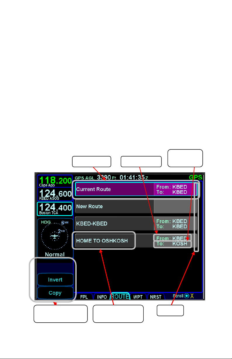
Route Management
Controls
Routes
Route Identifier
that you entered
Active Route
Origin Airport
Destination
Airport
SAVING/NAMING A FLIGHT PLAN
From the Route tab of the FMS page, the current route, labeled
Current Route, will be highlighted in magenta. If a valid origin and
destination have been created in the flight plan (e.g. “KBED –
CYQI”), the title will include these.
To edit the name of a flight plan, use the outer ring of the bottom
right bezel knob. Scroll up or down the route list until the desired
flight plan is highlighted by a surround cursor. By pushing the
knob, the selected route will load and the route name field will be
shown in reverse video. Touch the reverse highlighted name field
or push the bottom right IFD knob to generate a virtual keyboard
with which to type the desired name. To accept the new route
name press either the “ENTR” bezel key or the Enter button on
the keyboard.
Saving a Flight Plan
FMS Pages 2-7
Page 46

ACTIVATING A FLIGHT PLAN
While you always have the option to manually activate the flight
plan via a LSK on the Flight Plan tab, the created plan on the
Flight Plan tab will automatically activate on takeoff roll when a
threshold groundspeed is achieved (which is approximately 40
knots). If you built the flight plan on the “Route” tab, then you will
need to manually activate it via the “Activate Route” LSK on the
left side of the display.
COPYING A FLIGHT PLAN
From the “Route” tab of the “FMS” page, first select the route you
wish to copy via the bottom right-hand knob or by touching the
desired route, then press the “Copy” LSK on the left side of the
bezel. This will present the route name in reverse video. You can
either retain the pre-filled name or type a new one via the
keyboard. Follow by pressing “Enter”. Now use the knob to scroll
up or down the flight plan and edit it as required. If no editing is
required, you have successfully saved or copied a flight plan.
INVERTING A FLIGHT PLAN
From the “Route” tab of the “FMS” page, use the bottom right
knob on the IFD to scroll up or down the list of routes to the
desired flight plan or touch the desired route to invert. Press the
“Invert” LSK. This automatically inverts the flight plan and leaves
the route name field highlighted in reverse video, allowing you
type a new flight plan name, if desired.
PREVIEW FLIGHT PLANS
The flight plans (and procedures) can be previewed as they are
being built while on the FMS page, using the FPL tab with the
map partially exposed (Map-FPL split page as defined in Section
1 of this manual). As a flight plan is being built from that page,
the map will automatically resize to continue to display the entire
flight plan. Similarly, if a procedure is being added to a flight plan,
the procedure selected from the dropdown list and the selected
transition are drawn in real time on the automatically re-sizing
map for visual confirmation of the choice.
2-8 FMS Pages
Page 47
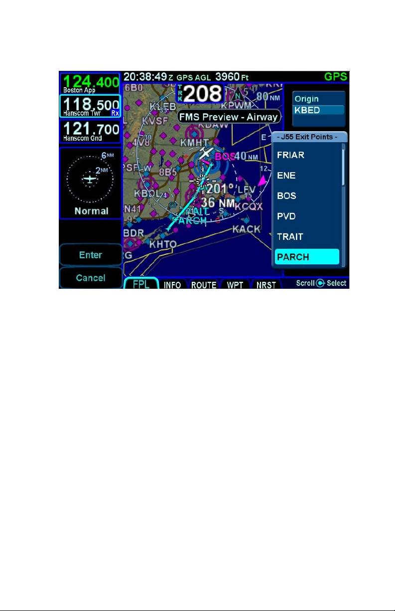
Previewing a Flight Plan While Building It
While in this mode, a temporary “FMS Preview - Waypoint”,
“FMS Preview - Airway”, or “FMS Preview – Approach” message
is displayed at the top of the page.
MODIFYING A FLIGHT PLAN
You can modify an existing flight plan in the FMS or create a new
route while you are flying an existing one without affecting the
existing active route. Several of the more common tasks are
described below.
INSERTING A WAYPOINT
From the FPL tab, use the bottom right knob on the IFD to scroll
up or down the flight plan until the insert cursor is positioned
where the new waypoint is to be inserted. At that point, push the
knob to generate a drop-down box from the cursor position. Scroll
up and down in that drop down box until you find the option you
seek. Press the knob again on the desired option. If it involves
typing in a waypoint identifier, start typing on the virtual keyboard
that is displayed. Geofill™ will typically find the correct waypoint
by the 2nd character.
FMS Pages 2-9
Page 48

TIPS AND TECHNIQUES
Back-to-Back Duplicate Waypoints Restriction
The FMS will not permit entering back-to-back
duplicate waypoints. A duplicate waypoint can be
inserted elsewhere in the active flight plan (e.g.
“above” the active approach or as a dummy
waypoint “below” the published missed approach
waypoints.) if this becomes operationally required
during a flight scenario.
DELETING A WAYPOINT
From the FPL tab, use the bottom right knob on the IFD to scroll
up and down the flight plan until the edit cursor surrounds the
waypoint to be deleted. Press the “CLR” button on the right side
of the bezel to delete the waypoint. Continue pressing the “CLR”
button and it will walk up the flight plan deleting earlier waypoints
as you go. Waypoints can also be deleted by touching the
waypoint to be deleted and then selecting the L4 “Delete
Waypoint” LSK.
EDITING A WAYPOINT
From the FPL tab, the bottom right knob on the IFD can be used
to edit an existing waypoint. Using the knob, scroll up or down the
flight plan until an edit cursor surrounds the waypoint to be
modified. Use the inner ring of that knob to highlight one of the
editable fields with reverse video. Pushing the knob provides a
drop down box from which the changes can be made.
Alternatively, touching the field to be edited will display a virtual
keyboard which can be used to enter the desired data/changes.
2-10 FMS Pages
Page 49
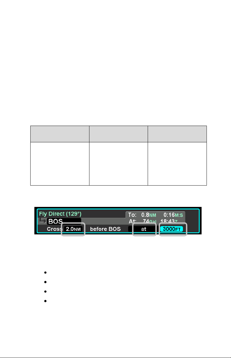
Cross
Type
Altitude
Number field
(selecting distance
in NM from
waypoint for
crossing constraint)
At Or Below;
At;
At or Above.
Altitude field
(selecting the target
altitude). Minimum
allowable value is
100’.
ADDING A VERTICAL CONSTRAINT
On virtually every waypoint, you can elect to assign a vertical
constraint (e.g. cross the waypoint at or above a specific altitude,
be at a specific altitude a specified distance prior to the waypoint,
etc). This is accomplished by ensuring an edit cursor surrounds
the waypoint of interest to select the waypoint and then either use
the bottom right inner knob or touch the desired field to highlight
one of the vertical constraint fields of the flight plan leg. Push the
knob and enter the desired value or double tap the field to display
a virtual keypad. This can be accomplished at any time on the
ground or in-air.
Vertical Constraint Choices
Vertical Constraint Fields
The default value for the crossing distance is 5.0nm for airports
and 0.0nm for all other waypoints.
The only waypoints that do not permit vertical constraints are:
Origin
Destination, if it has an approach selected
Missed Approach Point
Altitude Terminated Legs
FMS Pages 2-11
Page 50
ENTERING AND INTERCEPTING A RADIAL
FMS Method
The FMS Course function will allow the pilot to navigate “To” or
“From” the active waypoint while OBS is selected as the nav
source. Push the Nav Source knob in to make OBS the active
nav mode and then adjust the FMS (OBS) course using the
external course adjust knob (i.e. course set knob on a CDI or HSI
or EFIS). If there is no installed external course setting device,
then twist the IFD nav source knob to adjust the FMS Course
value.
FMS Course mode makes the current waypoint act like a VOR.
Select the desired radial to fly inbound or outbound. Adjusting the
course to or from the active waypoint will be reflected by the
To/From flag as in a traditional HSI. The course deviation
indicator will be presented in relation to the selected course.
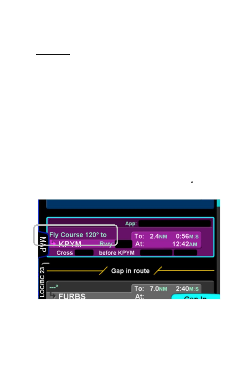
As the FMS course is adjusted via the external course set knob
(or the IFD nav source knob if no external device is installed), the
active leg on the FPL tab will change to “Fly Course xxx ” as
shown in the image below.
The FMS Course function will always be armed (i.e. it will always
intercept the flight plan) in a To intercept. If the airplane is in a
From course, it will intercept only if the dialed course trajectory
intercepts the flight plan. If the dialed course does not intercept
the flight plan, the airplane will fly that course indefinitely.
2-12 FMS Pages
Page 51

The FMS Course function will be exited when the airplane
intercepts the active waypoint in a To intercept or when
intercepting a downpath leg in the From case. Pressing the nav
source knob while the FMS course function is active will also
cancel the FMS Course mode and return to GPS as the active
nav source mode. The FMS Course will remain active if a From
course is dialed and the airplane does not intercept the FPL.
VLOC Method
If the Nav Source knob is set to VLOC as the active nav mode
and a VOR station is tuned and received, then use the external
course knob on the CDI/HSI/EFIS/etc to set the desired inbound
or outbound radial as required.
DELETING A FLIGHT PLAN
Select the “Routes” tab of the FMS page. Use the bottom right
IFD knob to scroll to the desired flight plan in the list or touch the
flight plan to highlight the route. Press the “CLR” button on the
bezel and a green confirm dialog box pops up. Press “Enter” or
“Cancel” LSKs or use the bezel “ENTR” or “CLR” buttons to finish
the deletion.
CREATING A HOLDING PATTERN
A hold can be put on any waypoint that has a fix terminated leg –
waypoints that terminate with a lat or lon position such as
navaids, enroute waypoints, user waypoints, airports, etc. Legs
that terminate at an altitude, DME distance, radial crossings, etc.
do not support attaching a hold.
Use the edit cursor on the flight plan to select the waypoint of
interest, then push the bottom right IFD knob or touch the desired
location to display a drop down list of options. Near the top of that
list, you will see “Hold at <waypoint name>”. Scroll to highlight
that drop down list entry and push the knob again. You have just
added a holding leg, populated with standard hold data.
Alternatively, use an insert cursor by positioning it where you
want to insert a hold in your flight plan. Push in the bottom right
IFD knob or touch the position on the glass. Note that a hold is
available via the drop down list. Scroll up or down the dropdown
list as required and push the bottom right knob or touch the hold
FMS Pages 2-13
Page 52
option in the list to insert a hold flight plan leg.
DELETING A HOLDING PATTERN
To delete a holding pattern in your flight plan, use the bottom right
IFD to scroll as required to create an edit cursor surrounding the
holding leg, or touch the hold leg to be deleted then press the
“Delete Hold” LSK.
EDITING A HOLDING PATTERN
Position an edit cursor around the holding leg of interest in your
flight plan. Use the inner ring of the bottom right IFD knob or
touch the field to be edited to highlight the desired field (e.g. turn
direction, leg length, leg units, inbound leg course) and make
your edit. Any changes made will immediately be applied.
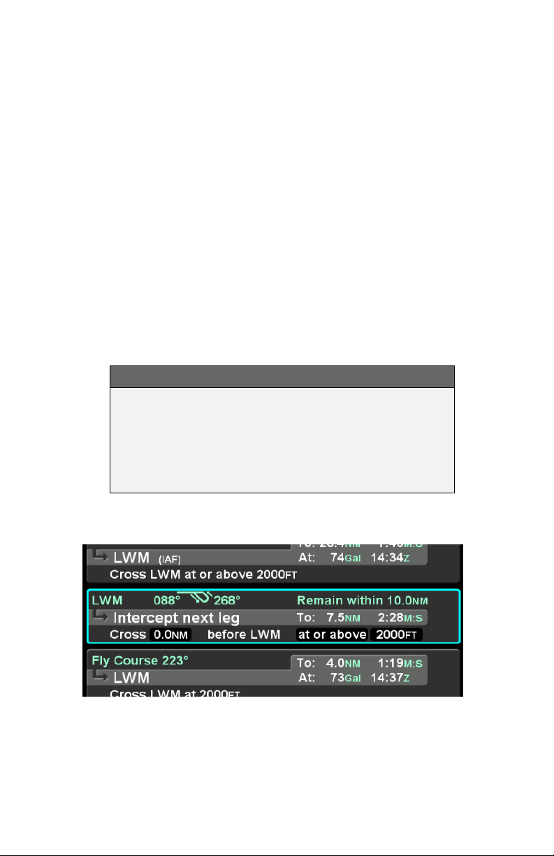
COOL FEATURE
Graphical Flight Plan Leg A graphical
representation of each leg of a flight plan may be
displayed within the FPL leg as shown in the image
below. This is especially useful for procedure turns
and holding patterns.
Procedure Turn with Course Reversal
2-14 FMS Pages
Page 53

FLIGHT PLAN SEQUENCING
The FMS assumes that the pilot will fly the flight plan as defined.
If that does not occur, legs may not sequence as expected.
Therefore, to manually sequence the desired leg, select it by
either using the bottom right IFD knob or touch it and press the
“Activate Leg” LSK followed by accepting the confirm dialog box
when it is displayed. Doing so will turn that leg magenta,
confirming that it is now the active leg.
TIPS AND TECHNIQUES
Impending Turn Notification
If flying the defined flight plan, the IFD will provide a
message about an impending turn that includes the
upcoming desired track (DTK) and a 10 second (30
second if the required turn is more than 120
degrees) count down.
COOL FEATURE
Automatic VOR Tuning
The FMS will automatically tune the next down-path
VOR in the active flight plan into the primary nav
frequency slot.
TIPS AND TECHNIQUES
Times to Turn Off Automatic VOR Tuning
Sometimes it is desirable to turn off the Automatic
VOR tuning feature via the “Auto-VLOC Tuning”
selection in User Options on one of the IFDs in a
dual IFD installation. An example of when this
might be desirable is if you want to depict a crossing
radial on IFD #2 for reference before crossing a
VOR.
FMS Pages 2-15
Page 54
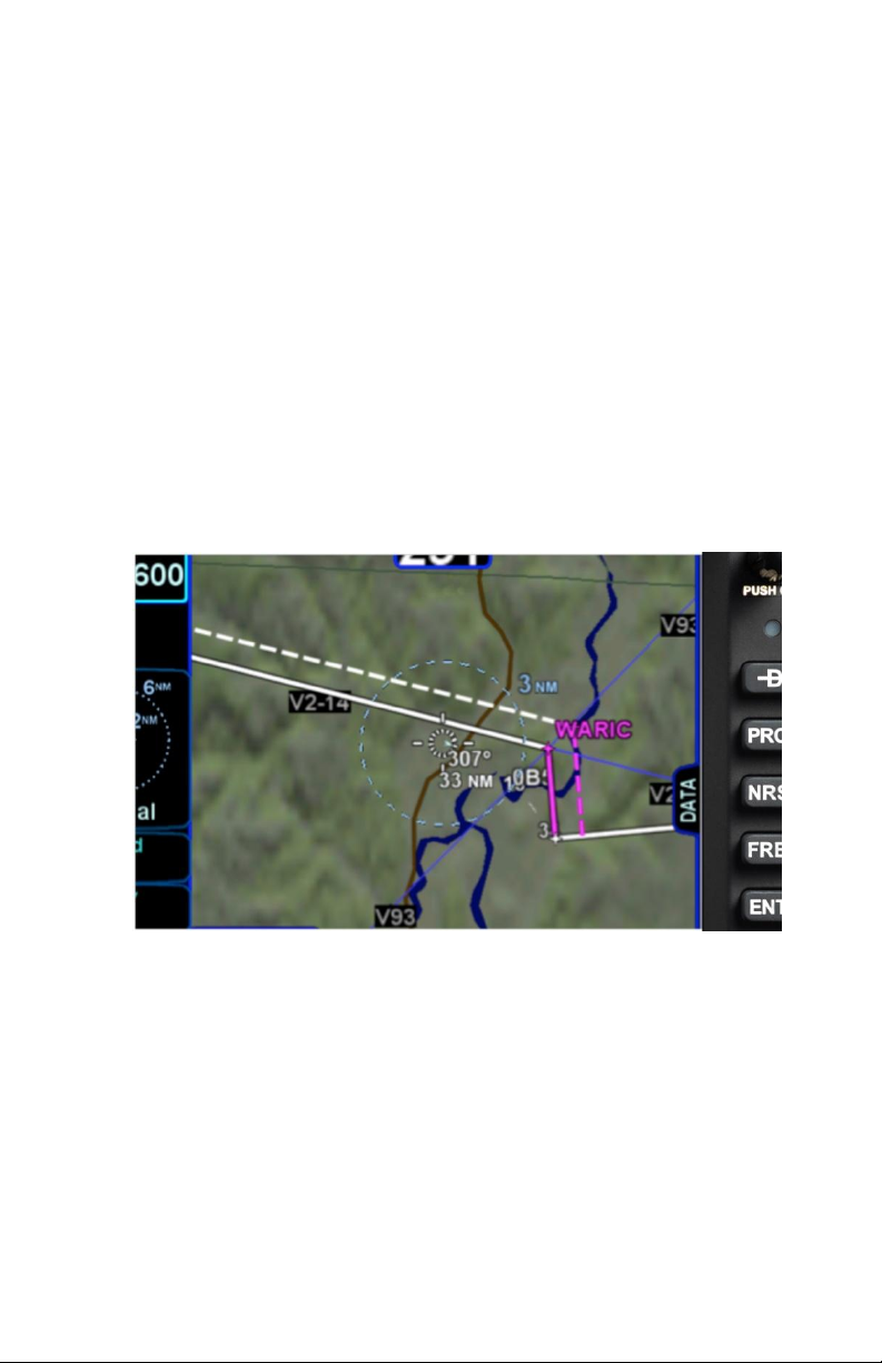
LATERAL OFFSETS
The system supports a capability to create and fly a lateral offset
from your flight plan. From the “FPL” tab of the FMS page, press
the “Offset Route” LSK and use the right-hand knob on the IFD to
dial in the desired offset. Use the outer ring for coarse control (1
nm increments) and the inner ring for fine control (0.1 nm
increments). Rotate the knob left for left offsets and right for right
offsets. Once the intended offset has been entered, press the
“Confirm Right/Left x.x NM” LSK. At that point, the original LSK
will indicate “Offset Route Right/Left X.X NM”. To delete a lateral
offset, press the “Delete Offset” LSK. The maximum offset that
can be dialed in is 20 NM. Lateral offsets are not available when
in OBS mode. Lateral offsets are unaffected by graphical route
planning (“rubber banding”) operations.
Lateral Offset Map Depiction
GAPS OR DISCONTINUITIES IN FLIGHT PLANS
A “Gap In Route” will appear within the flight plan when there is a
discontinuity between legs. A discontinuity occurs when the FMS
cannot compute the guidance to the next leg due to an invalid leg
type combination based on preset guidance rules. The objective
is to inform the pilot that the Gap must be manually closed if you
wish to sequence to the next waypoint. Otherwise, the leg before
the Gap will not be sequenced and guidance will not be provided
2-16 FMS Pages
Page 55
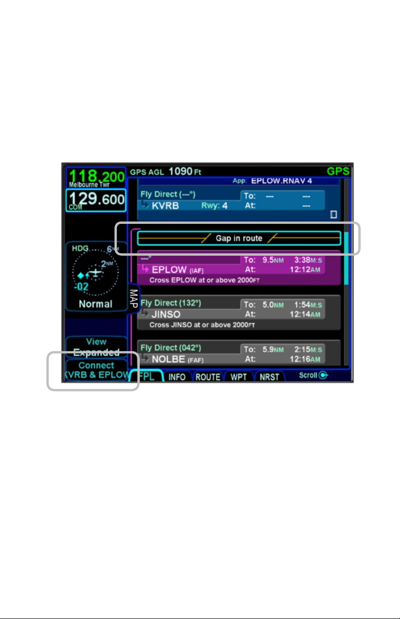
to the next waypoint. If desired, close the gap by placing the
cursor on it using the bottom right IFD knob or by touching it.
Press the “CLR” bezel key or the L4 LSK on the FPL tab,
“Connect <wpt1> & <wpt2>”. Closing a Gap connects the
waypoint prior to the Gap with the waypoint that follows by a
direct (straight) leg.
Connecting Gap in Route
Avidyne recommends that you input the arrival and approach for
the destination airfield and alternates into the FMS flight plan.
Selecting a published arrival and/or approach will automatically
load the procedure including all altitude constraints into the FMS.
Take advantage of the system to stay ahead of the airplane by
using the wind vector datablock selection (a constant calculation
of estimated wind direction and speed) for arrival planning, and
the electronic checklists and various map views.
FMS Pages 2-17
Page 56
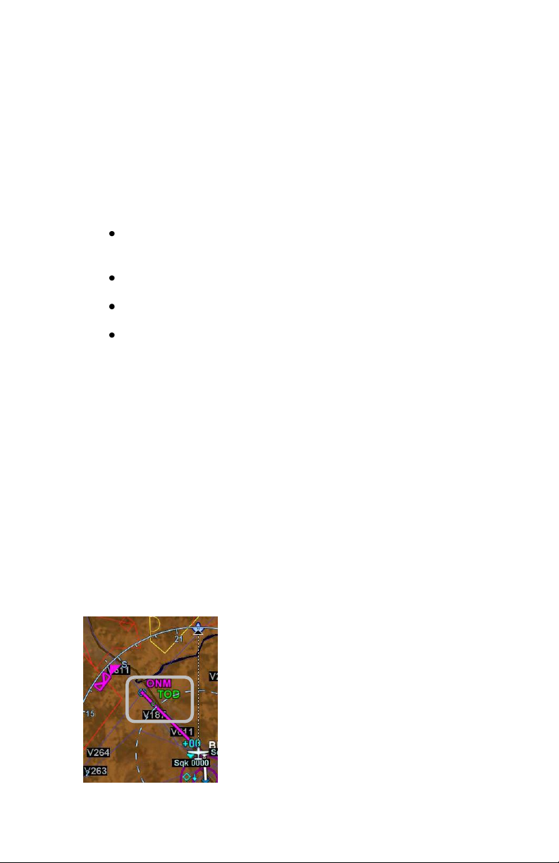
ENROUTE DESCENTS
A green circular top of descent (TOD) marker and label is drawn
on the map when flying “on-path” along the FMS flight plan, giving
a clear visual cue when it is appropriate to begin the enroute
descent. It is based on the vertical constraint associated with a
down-path waypoint.
To generate the TOD feature:
There must be an altitude constraint defined on at least one
down-path waypoint at least 50’ below present altitude;
There must be a valid GPS MSL Altitude or Baro Altitude;
The aircraft is less than 2nm from the active leg centerline;
Aircraft course is within 45 degrees of Desired Track (DTK).
The TOD function is not available on any waypoint of an
approach past the Final Approach Fix (FAF), or in holds, or
procedures turns.
The FMS uses a default of 500 feet per minute descent rate (or
as edited in the “Preferred Descent Rate” field on the FMS Setup
page).
There is an associated tone (sounds like a door bell) and CAS
countdown message 10 seconds prior to reaching the TOD point.
The “TOD” label may be auto-decluttered from the map
depending on map range and feature density. The TOD depiction
and CAS message are removed from the map immediately after
passing the TOD point.
Top of Descent (TOD) Marker
2-18 FMS Pages
Page 57

COOL FEATURE
Enter Approaches for Multiple “Destinations”
The FMS will allow multiple airfields or destinations
to be built into the flight plan. Each can have the
published approach and missed approach as part of
the plan. This is useful in pre-building your primary
destination with a missed approach, expected
alternate and its published approach. Similarly, a
training flight with multiple intended approaches and
locations can all be created in a single flight plan,
before takeoff.
TIPS AND TECHNIQUES
Check Altitude Too Low CAS Message
The IFD contains a yellow caution CAS message
that is active whenever an approach has been
activated and the aircraft altitude is below the Final
Approach Fix (FAF) published altitude.
If your flight plan contains consecutive approaches
and you activate the next approach during climb out
from the previous approach and prior to reaching
the next approach’s FAF altitude, this “Check
Altitude Too Low” message may be displayed.
ENTERING AN ARRIVAL AND APPROACH
From the FPL tab, use the bottom right knob on the IFD to scroll
up or down the flight plan as required until the edit cursor
surrounds the waypoint from which a published arrival and/or
approach is to be inputted. Twist the inner knob until either the
arrival or approach fields are highlighted. Push the knob to
generate a dropdown list from which to select the desired arrival
and/or approach, including Vectors-To-Final (VTF). As soon as
one is selected, the arrival or approach field displays the name of
the selected procedure and new legs are automatically added to
the flight plan. If a runway is entered before an arrival is entered
FMS Pages 2-19
Page 58
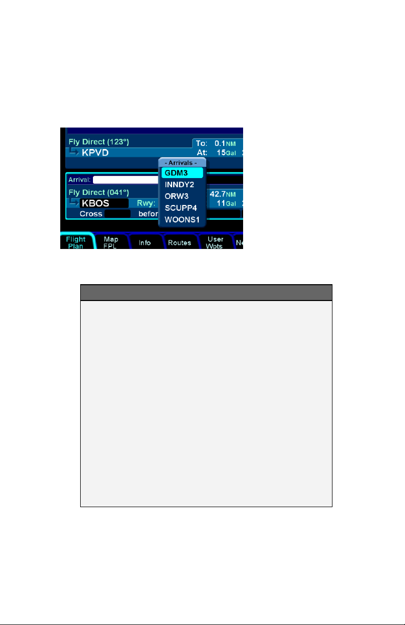
and the runway does not belong to the arrival, the arrival is not
accepted in the flight plan. A labeled white vertical line then
brackets the procedure in the flight plan as another visual cue
that the procedure is part of the flight plan.
Adding an Arrival
TIPS AND TECHNIQUES
FMS Preview
A FMS Preview mode is available on the FPL tab
(split Map-FPL view) of the FMS page. As soon as
changes start to be made to the FMS flight plan
while on that tab, real-time overlays of the edited
procedure, hold pattern, waypoint or airway are
presented on the map in cyan. There may be a fewsecond delay when drawing the edited route as the
system determines the optimum map range for
display. This feature provides a graphical preview
of the edited route before it is officially part of the
flight plan, to aid in flight planning. It can be used on
the ground or in-flight and is additionally identified
by an annunciation on the map part of the tab, “FMS
Preview - <type field being edited>”.
2-20 FMS Pages
Page 59
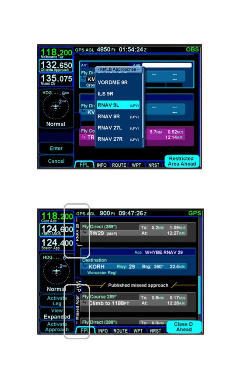
Approaches Dropdown Box
Procedures Brackets
FMS Pages 2-21
Page 60

COOL FEATURE
PROC button The “PROC” function key on the
bezel acts as a shortcut for attaching a published
arrival or approach procedure to a waypoint in your
flight plan. It can be used at any time. The first press
of the function key results in the IFD displaying the
“FPL” tab (Map-FPL view) of the FMS page with the
Approach field of the next destination after the
active leg highlighted in reverse video and a drop
down box of available published approaches listed.
Pressing it a 2nd time will step the reverse video
over the Arrival field and present a drop down box of
available published arrivals. Each subsequent press
of the “PROC” key will step through all following
destination airfields approaches and arrivals in the
flight plan and wrap back around to the top of the
flight plan. When you have the drop down box over
the intended field, use either the bottom right knob
on the IFD or touch the list to scroll up or down the
list until the desired procedure is selected, then
push that knob in to add that procedure to the flight
plan.
If there is no flight plan, then pressing the “PROC”
function key will present the “FPL” tab on the IFD
with an insert cursor at the top of the page but will
not present any procedures.
TIPS AND TECHNIQUES
Changing Selected Approach Type on Final
If a VHF-based approach has been activated and
then is replaced with a new GPS-based approach
prior to activating the missed approach, it may be
necessary to manually change the nav source mode
(e.g. manually change VLOC to GPS if switching
from an ILS to a RNAV).
2-22 FMS Pages
Page 61
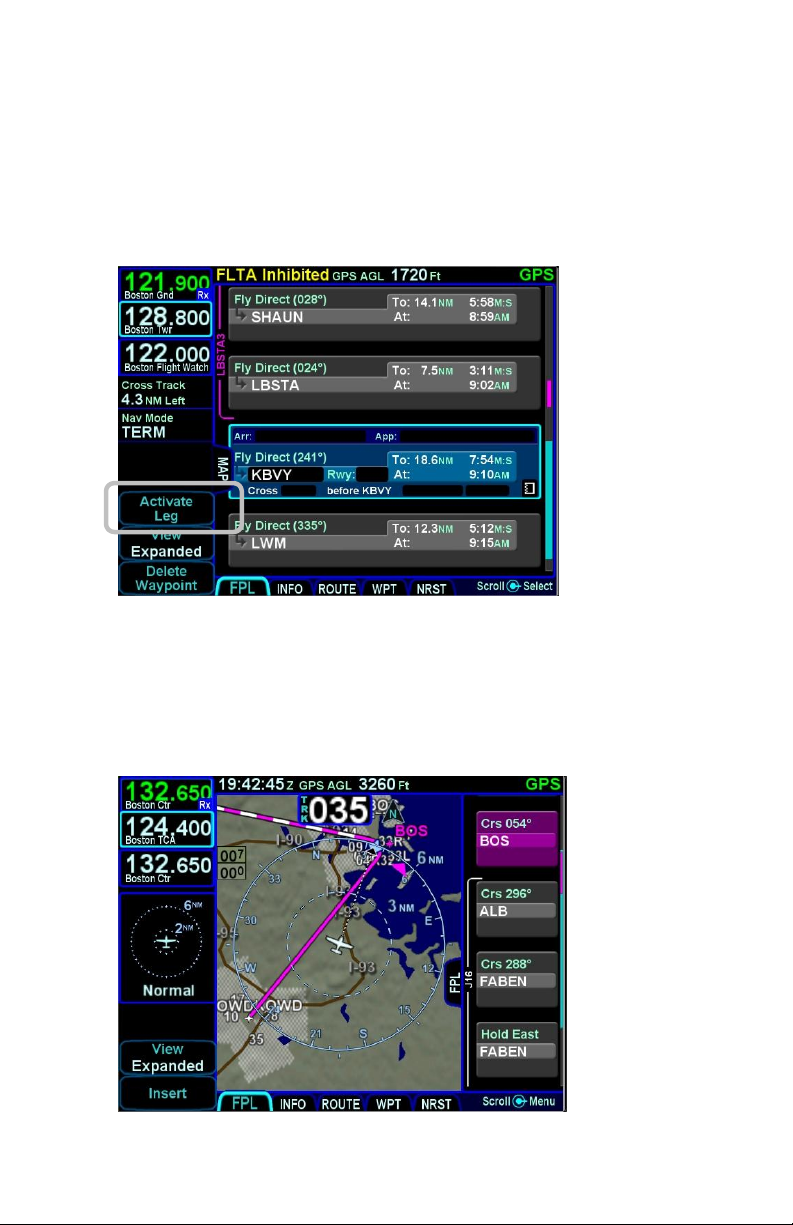
ACTIVATING A LEG
To activate a different leg of the flight plan from the FPL tab,
either use the bottom right IFD knob or touch the desired leg to
highlight it and then select the “Activate Leg” L2 LSK.
Activating a Leg
USE OF THE MAP-FPL SPLIT PAGE
While it can be useful in many phases of flight and scenarios, the
split page is especially helpful during arrivals.
Map-FPL Split Page
FMS Pages 2-23
Page 62
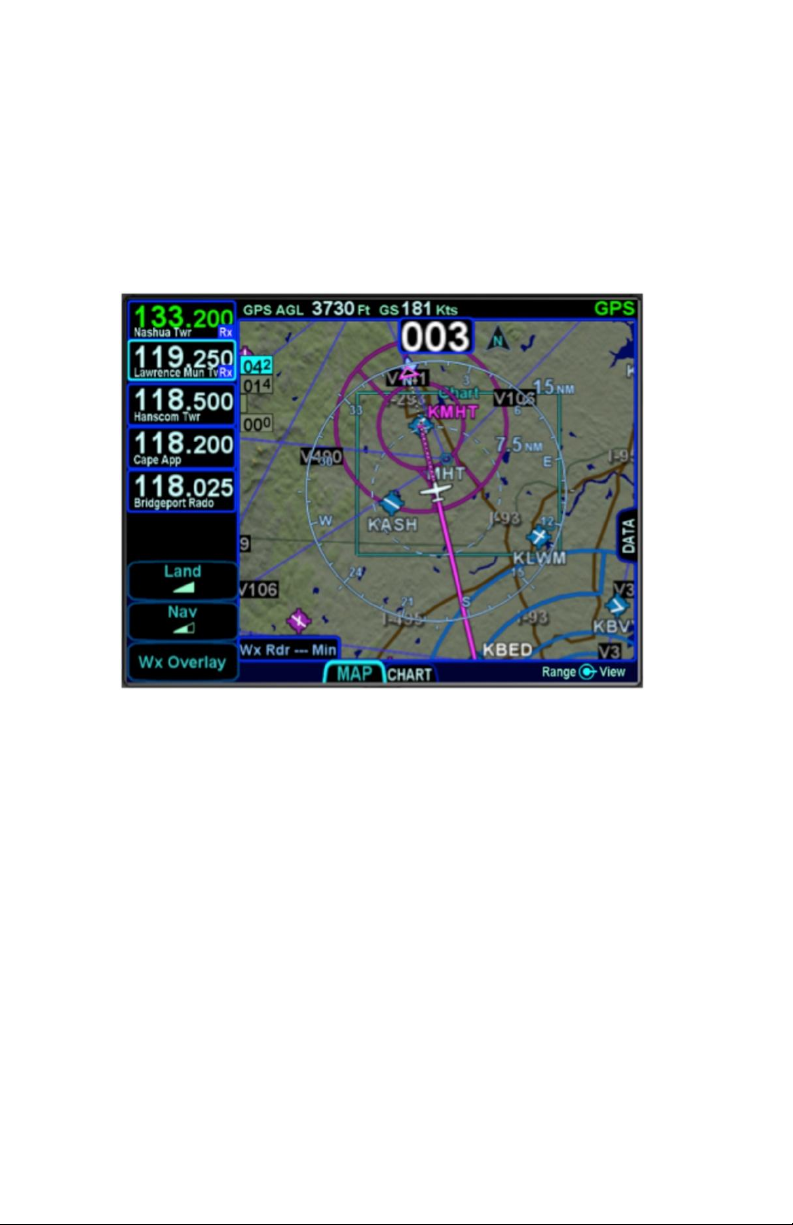
A green chart extent box is separately drawn on the map and
represents the geographic boundaries of an instrument approach
plate associated with a FMS destination. When the ownship
symbol crosses the boundary of the chart extent box, this is a
good time to switch over to the Chart tab on the MAP page.
Chart Extent Box
The Map-FPL split tab on the FMS page presents the moving
map on the left and the FMS flight plan in a thin strip on the right.
This can be most useful to instantly correlate your flight plan with
the graphical depiction on the map. This aids in error reduction
and helps visually see options for diverts, weather avoidance, etc.
2-24 FMS Pages
Page 63
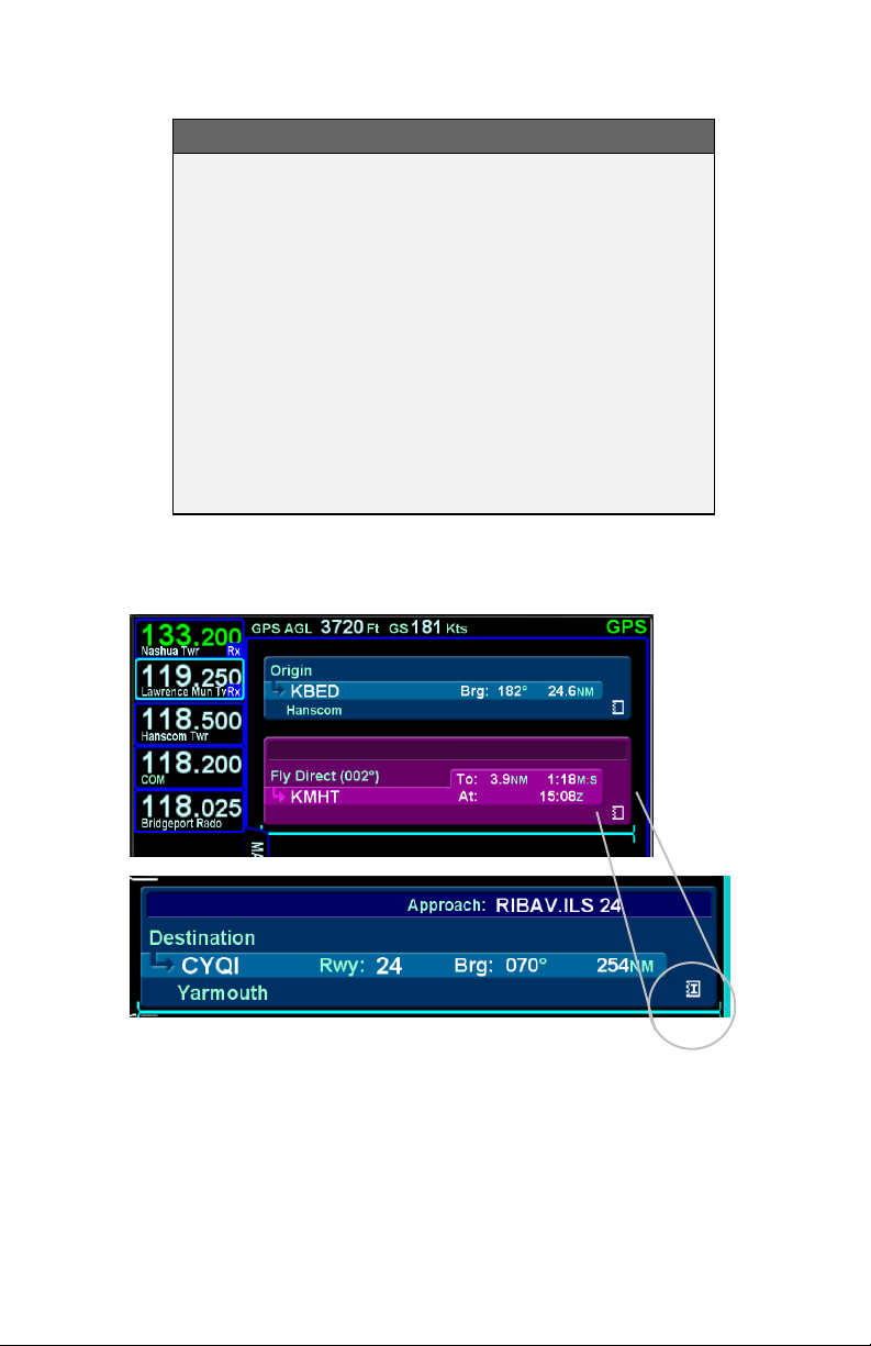
COOL FEATURE
Hot Links to Charts in Flight Plan Whenever a
flight plan leg (blue airfield legs) has at least one
published approach associated with it, a chart icon
is presented on the right edge of the flight plan leg.
If there is a published precision approach, the icon
will also contain an “I”. By using the right-hand knob
on the IFD, scroll through the flight plan elements
until the chart icon is highlighted in reverse video. If,
at that time, the knob is pushed in, the IFD will
display either the specific chart for that associated
procedure or the directory of possible procedures
for that airfield.
Hot Links to Charts
FMS Pages 2-25
Page 64
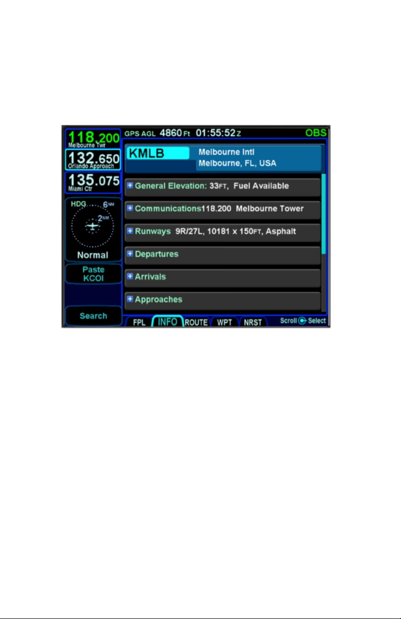
INFO TAB
The INFO tab of the FMS page provides additional information
about airports, navaids, and waypoints.
Info Tab
The facility (airport, navaid, waypoint) to which the information
applies will stay locked to the top of the page; the identifier field is
an editable field. To edit the identifier, either use the bottom right
IFD knob (inner ring or outer ring) as required to highlight the
identifier field and push in to get into edit mode and present a
virtual keyboard, or, touch the field to present a virtual keyboard.
There is also a Paste LSK along the left edge of the IFD that will
nominate the currently active leg of the flight plan or the flight plan
leg that is highlighted by a wrap-around edit cursor.
A search function, accessible via the Search LSK is also available
to help find the name of the facility for which more information is
desired.
If a nav frequency is associated with the facility displayed, then it
will be displayed in that same top block with the facility identifier
and can be nominated into the #1 standby nav slot by either
touching the frequency or by using the bottom right IFD knob to
highlight the frequency field and push the knob to nominate it into
the standby slot.
2-26 FMS Pages
Page 65

Depending on the type of facility being displayed, there are up to
7 category fields of information associated with the facility that
can be expanded (via the + symbol) or compacted (via the –
symbol) for additional details:
General – describes the facility (e.g. “Public
Towered Airport”), provides a thumbnail map of
the facility (the orientation and range of the
thumbnail map cannot be adjusted), provides
coordinates, elevation and magnetic variation
data, provides sunrise/sunset, provides density
altitude or access to a calculator to compute it,
provides fuel information, if applicable;
Communications – provides a list of frequencies
associated with the facility. Any one on the list can
be nominated into the #1 standby slot by either
touching it (first touch will highlight the field if
necessary, second touch nominates it into the #1
standby) or by using the bottom right IFD knob to
highlight the desired frequency and then push the
knob to nominate it into the #1 standby slot;
Runways – identifies the known runways at the
airport to include orientation, length and width, and
a thumbnail map of the runways. When an
individual runway row has been selected via touch
or the bottom right IFD knob, it can further expand
to provide surface type, coordinates of the
endpoints, runway bearing and elevation and the
graphical depiction will show lighting;
Departures – identifies the published departures
associated with the airport and when an individual
row has been selected via touch or the bottom
right IFD knob, it can further expand to provide a
thumbnail map depiction of the departure;
Arrivals - identifies the published arrivals
associated with the airport and when an individual
row has been selected via touch or the bottom
right IFD knob, it can further expand to provide a
thumbnail map depiction of the arrival;
Approaches - identifies the published approaches
associated with the airport including any identifier
and nav frequency, and when an individual row
FMS Pages 2-27
Page 66
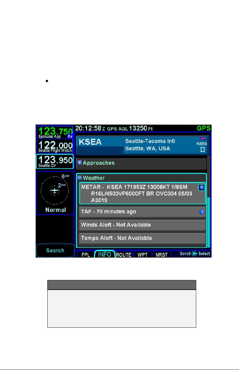
has been selected via touch or the bottom right
IFD knob, it can further expand to provide a
thumbnail map depiction of the approach. If the
nav frequency is selected by touch or by using the
bottom right IFD knob, it can be nominated
(copied) into the #1 standby slot;
Weather – provides four additional rows of data if
known: METAR, TAF, Winds Aloft, and Temps
Aloft. Selecting any of the additional rows via
touch or the bottom right IFD knob will display
additional sub-category data.
Four Additional Rows of Weather Data on Info Tab
NOTE
Map Switches
Switching between the thumbnail map on the INFO
tab and the main map on the MAP tab may result in
a 1-2 second delay as the new map re-sizes.
2-28 FMS Pages
Page 67
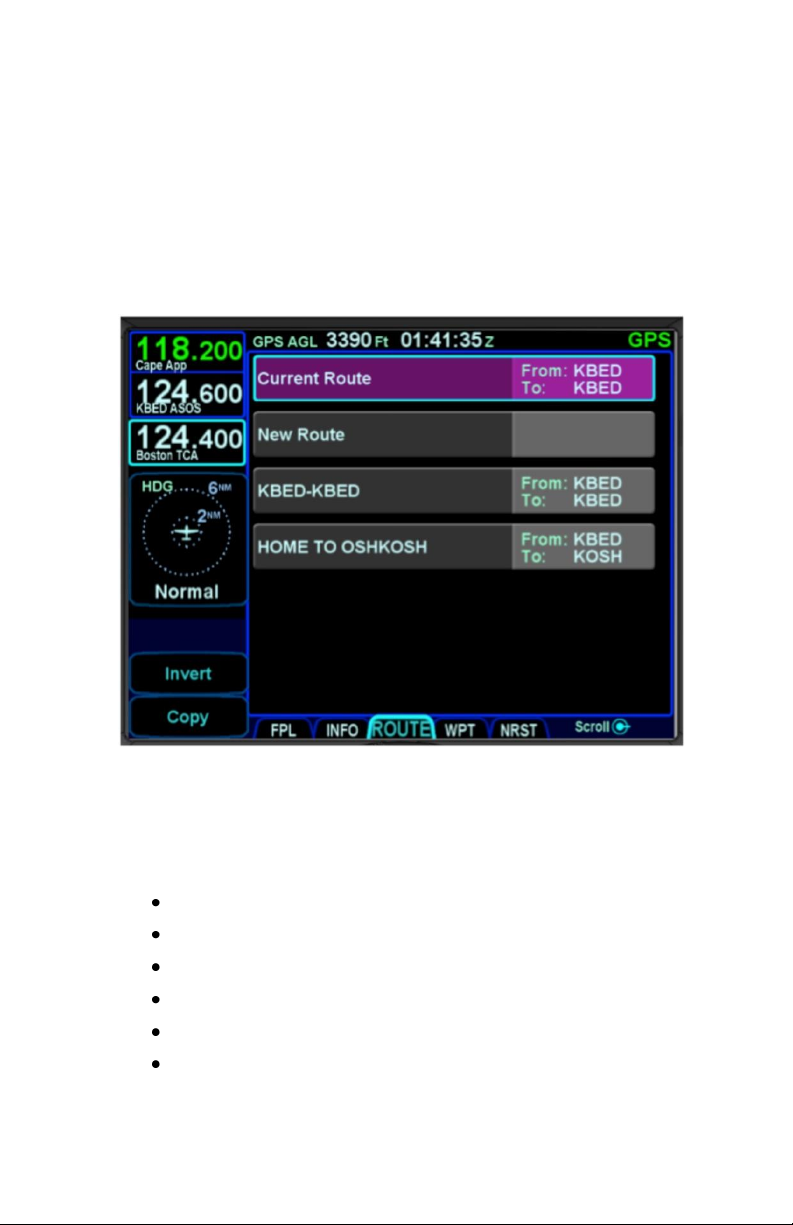
ROUTE TAB
The ROUTE tab is where flight plans or routes are stored within
the system. Up to 128 routes can be stored for later use, which is
useful for frequently traveled routes. A stored route must first be
“activated” via the “Activate Route” LSK, which makes it the
active flight plan and displays the flight plan (FPL) tab.
Routes Tab
As indicated in the above image, each stored route will have its
own row with the route name on the left and the origin and
destination waypoints identified on the right side of the row.
The Route tab has provisions to:
Create a new route;
Name a route;
Copy a route;
Invert a route;
Activate a route;
Delete a route.
FMS Pages 2-29
Page 68

CREATING A NEW ROUTE
In addition to using the FPL tab, a new flight plan route can be
created via the ROUTE tab. Use the bottom right IFD knob to
highlight the “New Route” row and then press the knob or touch
the “New Route” row to highlight, it then touch a 2nd time to start
creating a new route.
The route name field will be highlighted and a route name can be
created by either pushing in the bottom right IFD knob or by
touching the route name field to generate a keyboard. The
keyboard can be used or twist the bottom right IFD knob to start
creating a new route name. When the naming is complete, press
the “Enter” button on the keyboard or push the bottom right IFD
knob again to accept the new route name.
As soon as the route name is completed, an insert cursor will be
presented and any of the previously described methods for
creating a flight plan can be used.
After a flight plan is entered, use the “Back to Route List” LSK to
return to the directory of stored routes or press any other Page
Function key to move on to other tasks.
NAMING A ROUTE
An existing stored route can be renamed (or a new route named
for the first time) by highlighting the desired route from the
ROUTE tab, either by touching it twice or by using the bottom
right IFD knob to select it (twist the knob as required to highlight
the row and push the knob to put into edit mode).
Once the route is selected, the route name field will be displayed
with reverse video highlighting. Touching that highlighted route
name field or pushing in the bottom right IFD knob will begin the
route name editing. The desired route name can either be typed
into the virtual keyboard or entered by twisting and pushing the
bottom right IFD knob. When the desired name is complete,
press the “Enter” button on the keyboard or press in the IFD knob
to exit the naming edit mode.
2-30 FMS Pages
Page 69
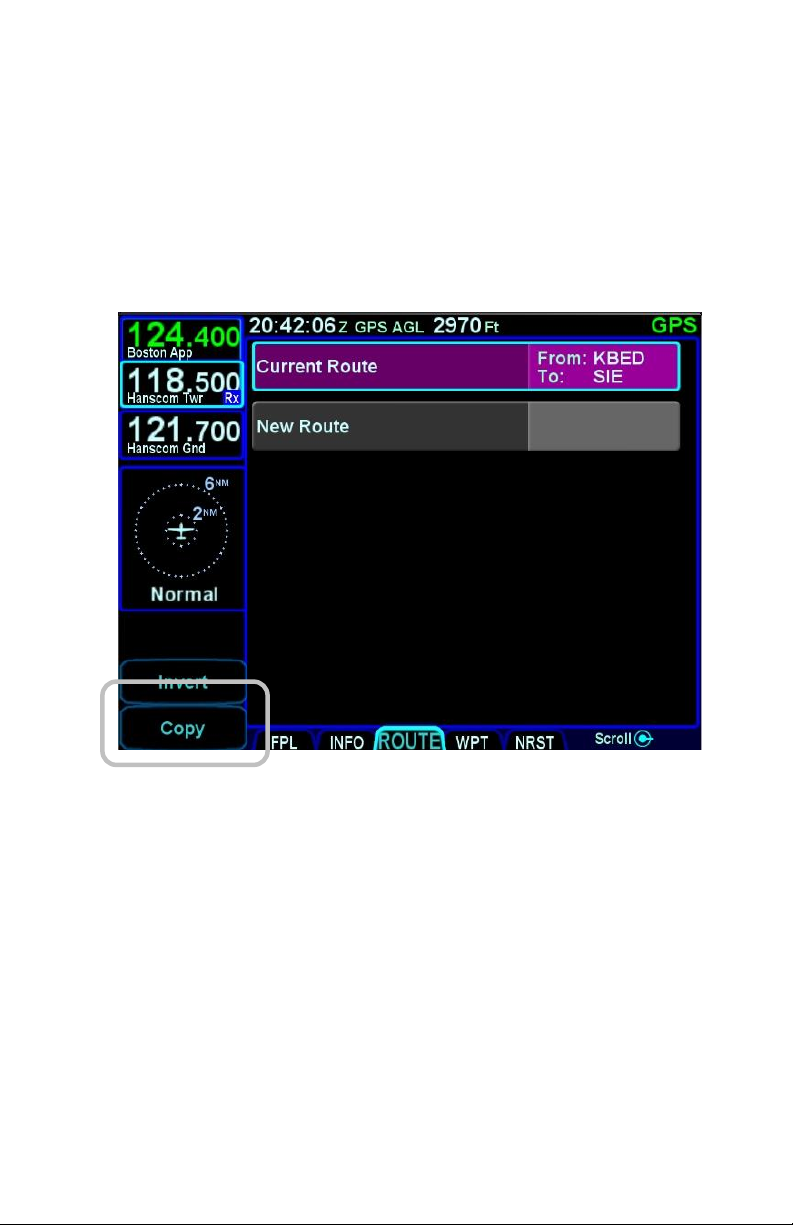
COPYING A ROUTE
To copy an existing route for later use or modification, highlight
the desired route from the ROUTE tab by either touching the row
or using the bottom right IFD knob. Once the desired route to be
copied is highlighted, press the “Copy” LSK along the left edge of
the display.
Copy Route LSK
This will present a copy of the original route that can then be
edited as required.
FMS Pages 2-31
Page 70
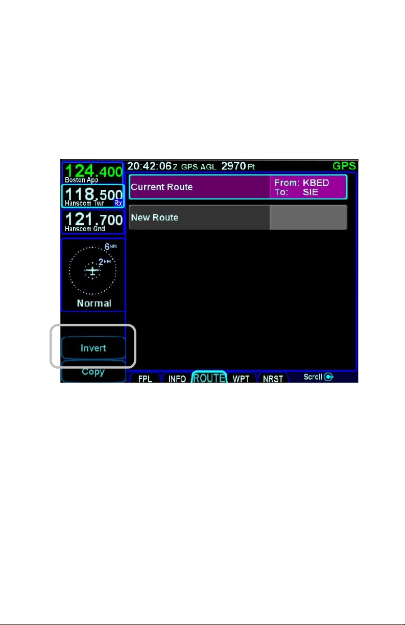
INVERTING A ROUTE
To invert an existing route for later use or modification, highlight
the desired route from the ROUTE tab by either touching the row
or using the bottom right IFD knob. Once the desired route to be
copied is highlighted, press the “Invert” LSK along the left edge of
the display.
Invert Route LSK
This will create an inverted copy of the original route that can then
be edited as required.
2-32 FMS Pages
Page 71
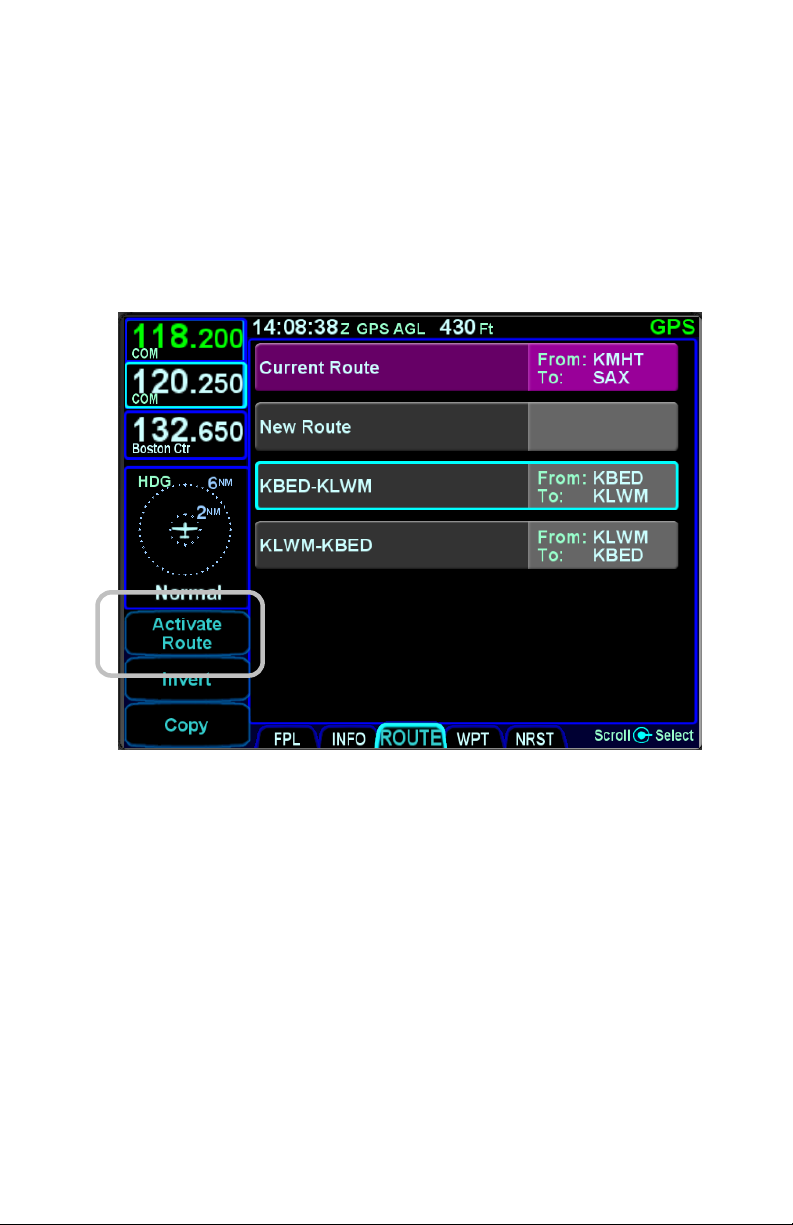
ACTIVATING A ROUTE
To activate an existing route from the stored routes list, highlight
the desired route from the ROUTE tab by either touching the row
or using the bottom right IFD knob. Once the desired route to be
activated is highlighted, press the “Activate Route” LSK along the
left edge of the display.
Activate Route LSK
This will display the now active route in the FPL tab.
DELETING A ROUTE
To delete an existing route from the stored routes list, highlight
the desired route from the ROUTE tab by either touching the row
or using the bottom right IFD knob. Once the desired route to be
deleted is highlighted, press the “CLR” function key along the
right edge of the display. A confirmation dialog box will then be
displayed (“Delete <name of flight plan>”) that can be confirmed
by either touching the dialog box or pressing the “ENTR” function
key along the right edge of the display.
FMS Pages 2-33
Page 72
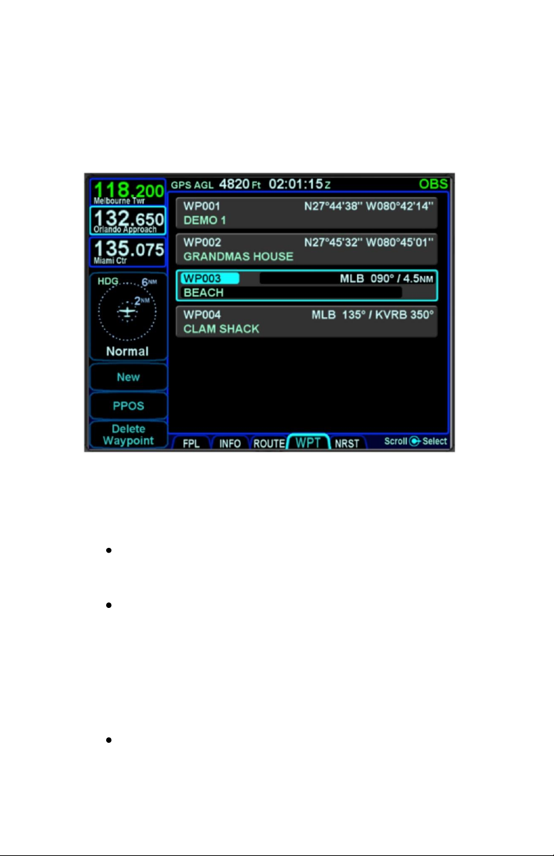
WPT (USER WAYPOINTS) TAB
The WPT tab will list all user waypoints in the IFD. Up to 600
user waypoints can be stored and accessed on this page.
User Waypoints Tab
CREATING A USER WAYPOINT
There are 4 methods of creating a user waypoint from the “WPT”
tab of the FMS page:
Present Position – Press the “PPOS” LSK to
create a waypoint with your current position. No
further action is required.
Enter Lat/Lon – Press the “New” LSK then press
the “Format” LSK until the “Lat/Lon” option
appears and enter in your desired coordinates
either by touching the coordinate field and then
using the virtual keyboard or by using a
combination of twists and pushes of the bottom
right IFD knob to enter the coordinates. Press the
“Enter” LSK to save that new waypoint.
Enter Radial/Radial (an intersection of two
radials) – Press the “New” LSK then press the
“Format” LSK as required to select the “Rad/Rad”
2-34 FMS Pages
Page 73

option and enter in your desired navaids and
radials either by touching the target field and then
using the virtual keyboard or by using a
combination of twists and pushes of the bottom
right IFD knob to enter the data. Press the “Enter”
LSK to save that new waypoint.
Enter Place/Bearing/Distance – Press the “New”
LSK then press the “Format” LSK as required to
select the “Rad/Dist” option and enter in your
desired place/bearing/distance either by touching
the target field and then using the virtual keyboard
or by using a combination of twists and pushes of
the bottom right IFD knob to enter the data. Press
the “Enter” LSK to create and save that new
waypoint.
Some external EFIS systems (e.g. Bendix King EFS 40/50,
Collins Pro Line 21, etc) can also create and send user waypoints
to the IFD. When the waypoint data is received from the external
EFIS, the IFD will automatically switch to the WPT tab if not
already there.
NAMING A USER WAYPOINT
Each user waypoint can be assigned a 5 character identifier that
can be used in the FMS anywhere a nav database waypoint can
be used. You can elect to use the automatically assigned 5
character identifier (format is “WP###”) or re-name that as
desired. A longer description can also be attached to each user
waypoint using the “Name” field. In each case, those names can
be entered by either touching the specific field and using the
virtual keyboard or by using a combination of twists and pushes
of the bottom right IFD knob.
DELETING A USER WAYPOINT
There are two methods to delete an existing user waypoint.
Either highlight the waypoint to be deleted and press the “CLR”
button on the bezel, and then the “ENTR” button when the green
confirm dialog box is displayed, or, use the “Delete Waypoint”
LSK along the left edge of the display and then use the “ENTR”
button when the green confirm dialog box is displayed (or touch
the green box).
FMS Pages 2-35
Page 74
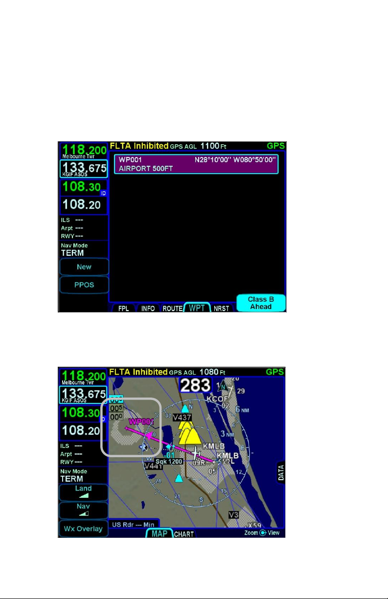
DESIGNATING A USER WAYPOINT AS AN AIRFIELD
To designate a user waypoint as an airfield, the waypoint must be
manually named using the following format
“AIRPORT XXXXXFT” where XXXX is the field’s elevation and
note that the space is critical in naming the point.
User Waypoint Airfield Naming Example
When used in a flight plan, the user-defined airport will display as
a no-known-runway-orientation type of an airfield on the map.
User Waypoint Airfield Depiction on Map
2-36 FMS Pages
Page 75
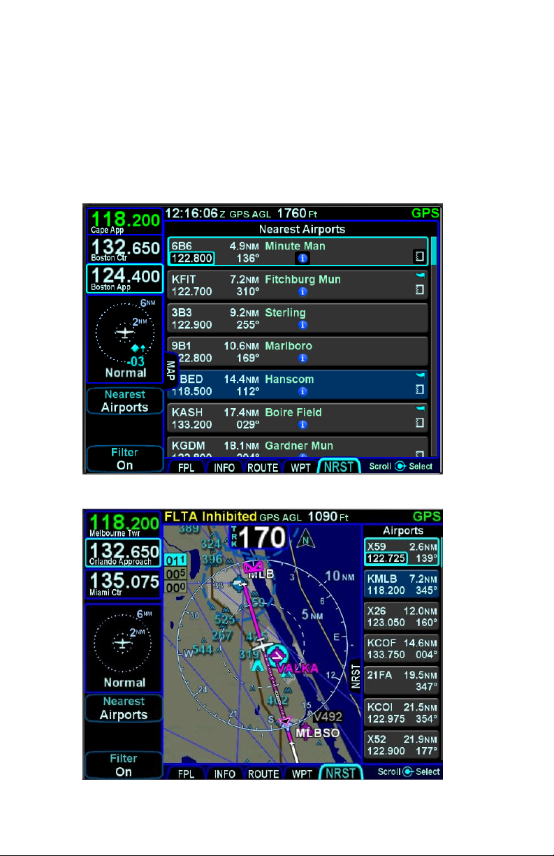
NRST (NEAREST) TAB
The Nearest page has two display formats – full page Nearest
and a split Map-Nearest combination. Switching between the two
formats is accomplished by “opening” or “closing” the side tab
when on the Nearest page.
Full Nearest Tab
Split Nearest Tab
FMS Pages 2-37
Page 76

The “Nearest” LSK along the left edge can be used to cycle
through the various nearest types. Choices include:
Nearest Airports
Nearest Airports to Destination
Nearest VORs
Nearest NDBs
Nearest Intersections
Nearest ARTCCs
Nearest FSS
Nearest Airspace
Nearest User Waypoints
When using the split Map-Nearest view, the row that is
highlighted in the Nearest list will also be highlighted in cyan on
the map.
For those rows that contain a frequency, touching the frequency,
or using the bottom right IFD knob to highlight it and then pushing
the knob will nominate the frequency into the #1 standby slot.
For those rows that contain a lower case blue info “i” symbol in
the middle of the row, touching the info “i” or using the bottom
right IFD knob to highlight it and then pushing the knob will jump
the page to the INFO tab with that facility information displayed.
For those rows that contain a chart icon on the right side,
touching the chart icon or using the bottom right IFD knob to
highlight it and then pushing the knob will jump the page to the
CHART tab on the MAP page with the Chart directory for that
airfield displayed.
For airports that have a METAR associated with them, a colored
METAR flag will be displayed on the right side.
Each Nearest type list can be scrolled either via touch (use a
vertical swipe of the finger) or via the bottom right IFD knob.
If the highlighted item is an airport, pressing the Direct-To
function key on the bezel will display the Direct-To green dialog
box with the highlighted airport pre-populated as the Direct-To
location.
2-38 FMS Pages
Page 77

As described in Section 1 of the manual, pressing the NRST
function key will bring up the Nearest tab in the split Map-Nearest
view.
Each subsequent push of the “NRST” function key will step to the
next nearest data type.
If the Nearest page is left for 60 seconds or more and then is
returned to, the Nearest Airports selection will be the active
nearest data type no matter what the last nearest data type may
have been. For example, if the Nearest VORs selection was the
most recent display of nearest data, and then the pilot selects a
map page for more than 60 seconds, when the Nearest tab is
next selected, Nearest Airports data is now displayed and not
Nearest VORs.
TIPS AND TECHNIQUES
Emergency Return to Departure Airfield
If on departure leg and an emergency return to the
departure airfield is deemed necessary, the
recommended technique is to press the –D-> button
on the bezel, twist the bottom right IFD knob
counter-clockwise to pre-fill the departure airfield
and press ENTR, ENTR to make that the active
waypoint. Then press the PROC key to produce a
dropdown list of approaches and select the desired
one. To quickly get the tower frequency of that
airfield, press the NRST button on the bezel,
confirm the departure airfield is the highlighted row
and press the bottom right IFD knob to nominate
that frequency into the #1 standby slot for swapping.
NOTE
Nearest Lists Capped at 100nm
Most Nearest lists will only display entries that are
within 100nm of the current aircraft position.
FMS Pages 2-39
Page 78

Page 79

3 Map Pages
This section covers the Map page tabs including the map and
chart display modes and controls, terrain awareness and alerting,
and weather datalink.
MAP TAB
The map has several formats and views. There is both a full map
depiction as well as a datablock map depiction. In both cases,
you have the ability to control the map feature density as well as
the various overlays, all via the LSKs along the left edge of the
display.
The active FMS flight plan is always overlaid on the map as are
any traffic depictions.
COOL FEATURE
Next Leg Depiction on Map
While the current leg of the active flight plan is
always depicted in magenta on all moving maps,
we’ve added an indication of the next leg using
alternating magenta and white stripes. This “candy
cane” indication can come in handy during such
circumstances as teardrop entries into a hold
pattern. It gives you a clear indication of what the
system will do next. All future legs beyond the next
leg will be depicted in white.
MAP CONTROLS
Turning the bottom right IFD knob (inner or outer ring) or using
“pinch zoom” touch gestures will result in a map range change.
Map range choices extend from 2 nm up to 1000 nm. Current
map range is indicated on the outer map range ring at
approximately the 1:30 position and as noted above, the map
range can be adjusted by either twisting the bottom right IFD
knob or by using a two-fingered pinching gesture on the touch
Map Pages 3-1
Page 80
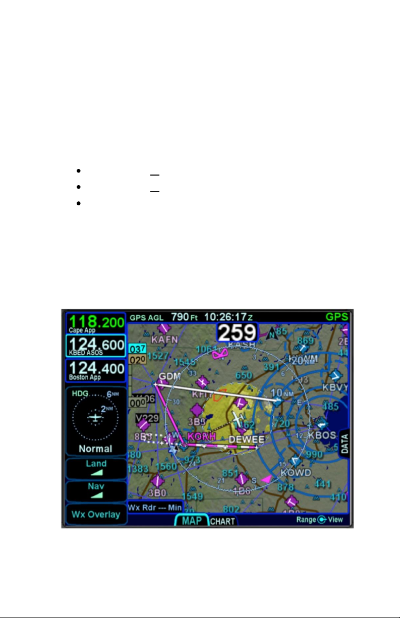
screen. The depicted current range numeric is replaced by “Min”
and “Max” for two seconds before timing back out to the actual
range number when at the two range extremes.
Pressing the knob cycles through the various map views. The
map view selected is indicated at the top of the map next to the
heading box. No indication means Heading Up. All other options
are labeled next to that heading box. Depending on the
installation, map view options can be:
Heading Up or Track Up (360°)
Heading Up or Track Up (240° arc view)
North Up (360°)
Heading vs. Track selection is made from the “Map Orientation”
selection on the User Options – SETUP tab of the AUX page.
North Up can be either Magnetic North or True North depending
on the “Bearing Reference” selection on the User Options –
SETUP tab of the AUX page.
North-Up, 360 View Example
3-2 Map Pages
Page 81
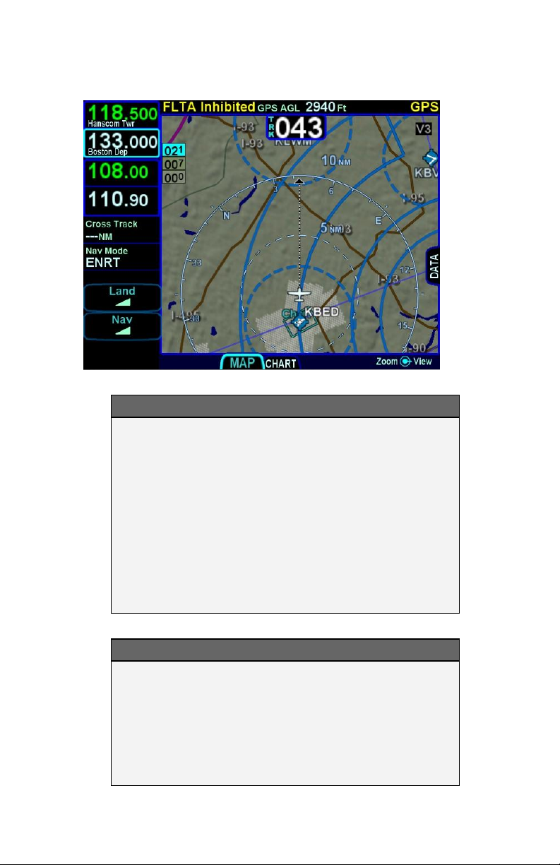
Track-Up, Arc View Example
TIPS AND TECHNIQUES
Map Content Control
Map features displayed are highly dependent on a
combination of the map view, map range, map
declutter settings, and user setup choices. For
example, if the flight plan concludes at an airfield,
the airfield identifier may be automatically
decluttered in favor of the waypoint identifier that
represents the airfield from the flight plan. In this
example, both identifiers can be made visible by
ranging in the map to under 4nm.
NOTE
Heading vs. Track Depictions
In configurations in which aircraft heading
information is unavailable, the map display will
orient the aircraft ownship symbol and other map
data to the aircraft ground track and continue to
display intruder aircraft oriented to heading.
Map Pages 3-3
Page 82
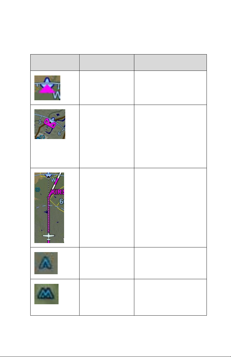
Map Symbol
Item
Description
Desired Track
Solid triangle on inside
edge of map compass
rose
Heading Select
(“Heading Bug”)
For those installations
where the IFD is
receiving heading select
(aka heading “bug”) data,
a hollow heading bug is
displayed for reference
on the inside edge of the
map compass rose
Projected track
line
Dashed line indicating
actual track. Connects
ownship symbol with
compass rose.
Single Low
Obstacle
200’ AGL up to 1000’
AGL
Grouping of low
obstacles
2 or more low obstacles
(200’ AGL up to 1000’
AGL) within 1 nm of each
other
OTHER MAP FEATURES
The table below defines other map features.
3-4 Map Pages
Page 83
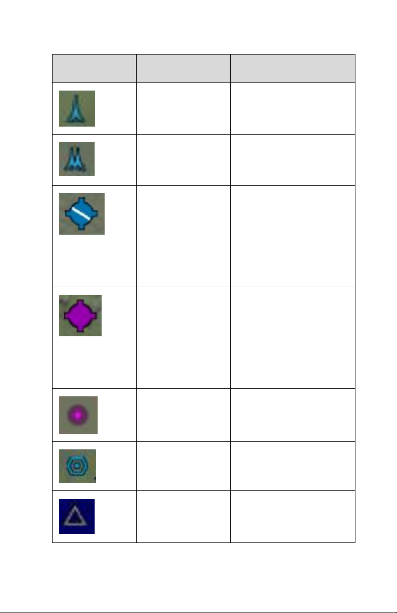
Map Symbol
Item
Description
Single high
obstacle
1000’ AGL or higher
Grouping of high
obstacles
2 or more high obstacles
(1000’ AGL or higher)
within 1 nm of each other
Towered airport,
hard
Towered airport,
soft
Towered airport,
water
If runway orientation
known, they are also
depicted on the airfield
symbol
Non-towered
airport, hard
Non-towered
airport, soft
Non-towered
airport, water
If runway orientation
known, they are also
depicted on the airfield
symbol
NDB
All NDBs in nav database
VOR
All VORs in nav
database
Intersection
All intersections in nav
database
Map Pages 3-5
Page 84
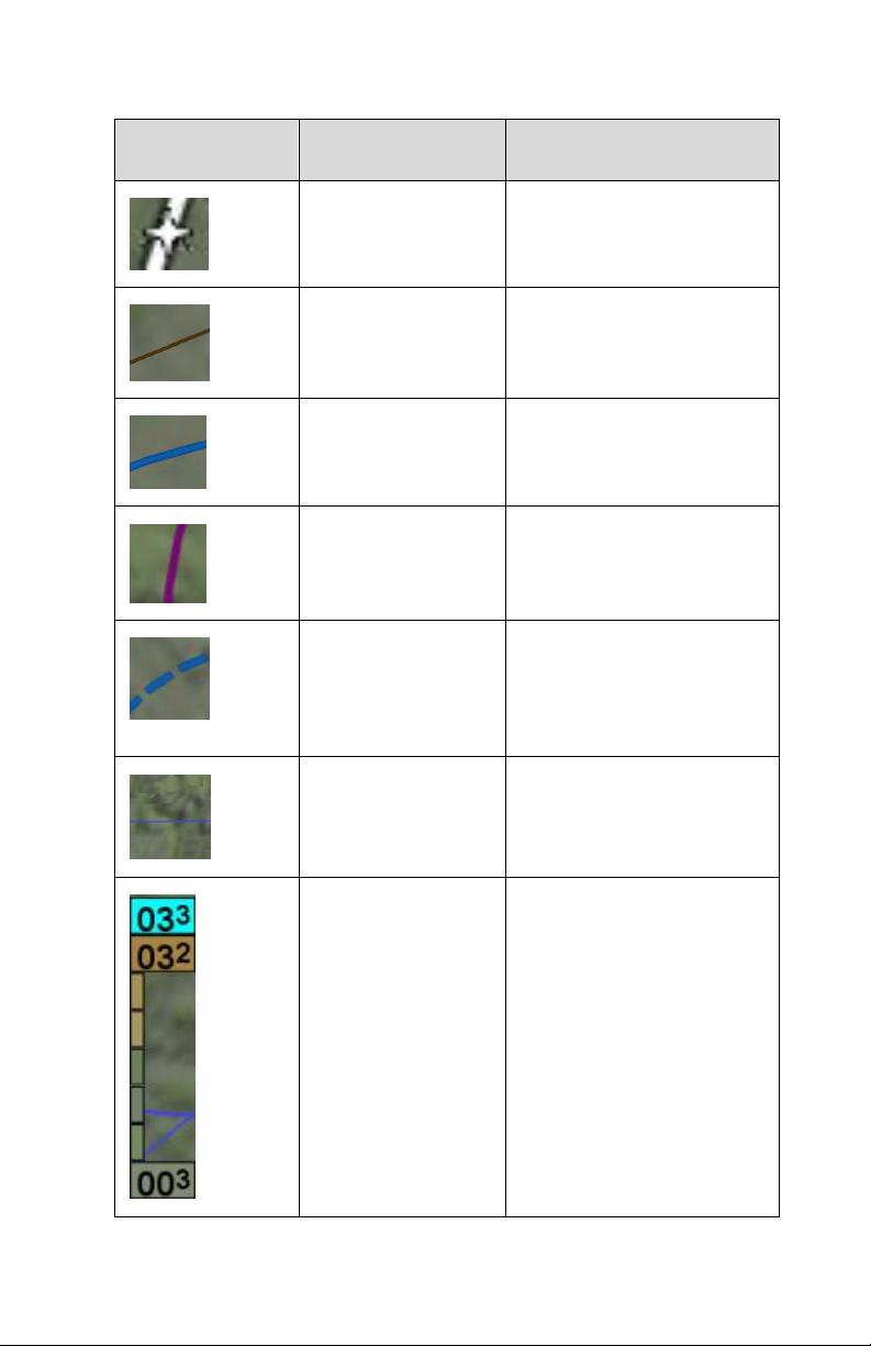
Map Symbol
Item
Description
Flight plan, course
waypoints
Each waypoint in flight
plan
Interstate highway
All interstate highways in
the database
Class B
Each boundary of Class
B airspace
Class C
Each boundary of Class
C airspace
Tower Zone
(estimated Class
D)
Tower zone boundary if
known, otherwise 5nm
ring estimating Class D
boundary
Victor or Jet
Airways
All Victor and/or Jet
airways
Terrain scale
Indicates highest and
lowest limits of the terrain
in displayed area.
Legend colors in
between these numerics
represent terrain
elevations. Blue
obstacle clearance
number shows the top of
the highest obstacle,
when greater than the
highest displayed terrain.
3-6 Map Pages
Page 85
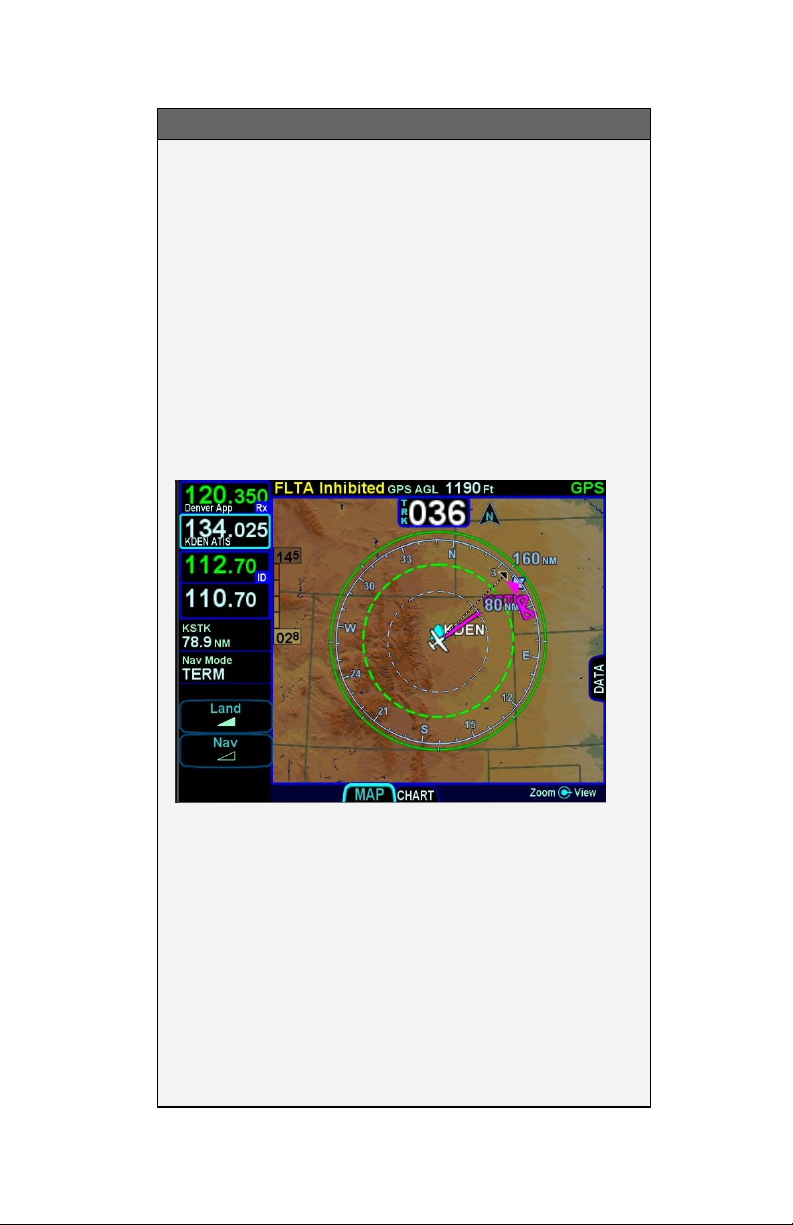
COOL FEATURE
Fuel Range Ring
The green fuel range ring depicted on the map
provides a visual indication of the max range of the
aircraft, allowing a 45-minute reserve. Winds are
indirectly taken into account. The calculation uses
groundspeed to compute the size of the circle and is
based on the value of the fuel totalizer. The dashed
green circle indicates the total maximum range
without using the reserve. A wider solid green circle
indicates the extra range the reserve fuel should
provide. The circle turns yellow indicating that only
reserve fuel remains. The rings are always
displayed and cannot be turned off.
The indications depicted are for a maximum fuel
range, calculated with reference to the current
groundspeed and the remaining fuel as indicated by
the fuel totalizer. Changes in power settings or
winds aloft or inaccurate fuel totalizer data will alter
your range and endurance depiction. There will be
no fuel range rings depicted if the IFD is not
connected to a fuel flow system. An inaccurate
manual entry of initial fuel will result in an inaccurate
fuel range ring depiction.
Map Pages 3-7
Page 86
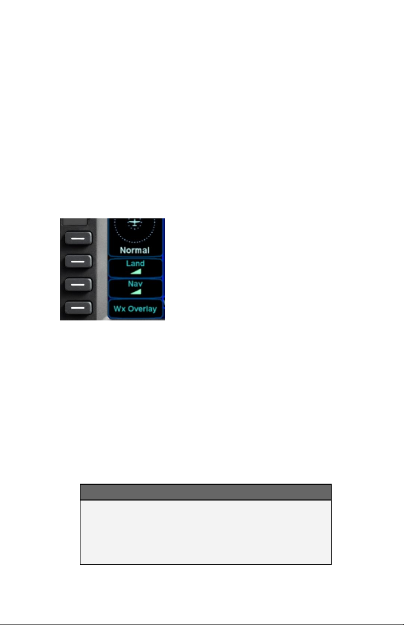
DECLUTTERING THE MAP
Two LSKs along the left edge of the display allow for separate
control of the information density of the land-based (“Land”) map
features (e.g. terrain, political boundaries, rivers, lakes, oceans,
roads, etc.) and the navigational-based (“Nav”) map features (e.g.
airspace, Victor and Jet airways, airports, obstacles, navaids,
etc.).
Use the “Land” and/or “Nav” LSK to select the preferred level of
feature density. The level specified remains consistent across all
map pages on the display on which it was set.
Map Declutter Controls
MAP PANNING
Panning the map is accomplished by dragging a finger along the
display in the direction of desired panning. When panning away
from the ownship depiction, a cross-hair cursor is displayed and a
readout of the bearing and distance from present position to the
cross-hair cursor position is displayed next to the cross-hair
cursor.
The map will snap back to being centered on the present-position
ownship depiction after 20 seconds of panning inactivity or if a
quick double-tap on the touch-screen is made.
NOTE
Map Panning Limited Geographic Boundaries
Due to map projection limitations, map panning is
limited to +/- 45 degrees of longitude and +/- 30
degrees of latitude from present position.
3-8 Map Pages
Page 87
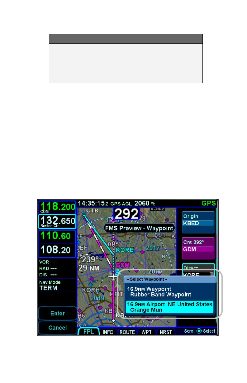
NOTE
Map Panning Only Via Touch
Map panning can only be accomplished via touch
screen use. There is no physical bezel control to
support map panning.
GRAPHICAL FLIGHT PLANNING (“RUBBER BANDING”)
A flight plan can be altered graphically by touching the desired leg
or the desired waypoint on the map depiction, placing your finger
on the leg for approximately 2 seconds until the leg turns cyan,
and then, without lifting your finger off the display, dragging your
finger to the desired location. When you lift your finger off the
display, a dialog box is presented on the display for you to
choose/confirm the new waypoint being created.
If the new fix is in close proximity to a facility or facilities in the onboard navigation database, then both the fix and the nearby
facility or facilities will appear in the dialog box list.
Rubber Banding Dialog Box
Map Pages 3-9
Page 88

If the intended new waypoint is not listed in the dialog box to your
satisfaction, press the bezel “CLR” button to clear and restart as
required.
As soon as a fix from the presented list is selected, a new
waypoint is inserted in the FPL flight plan list and uses a default
waypoint naming mechanism (“RBxxx” where “RB” stands for
Rubber Banding). This can easily be seen if the IFD were on the
FPL tab of the FMS page and using the split Map-FPL view.
TIPS AND TECHNIQUES
Optimal Rubber Banding
If you don’t see the desired leg turn cyan within 2
seconds of placement of your finger on the location,
try slightly adjusting the placement of the finger that
is being used to designate a leg for rubber banding.
Move your finger slightly in a direction perpendicular
to the leg. Note that the active leg (the magenta
one) of a flight plan cannot be rubber-banded.
Rubber banding is a handy feature to quickly alter a flight plan
around airspace or a weather buildup while staying on the map.
NOTE
Rubber Banding Only Via Touch
Rubber banding can only be accomplished via touch
screen controls. There is no physical bezel control
to support the feature.
3-10 Map Pages
Page 89
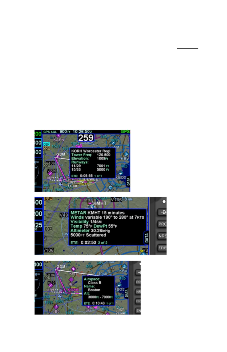
MAP INFORMATION POP-UP BOXES
There are “hot spots” all over the map and include every depicted
navaid, airport and airspace including TFRs. Touching one of
these “hot spots” will generate an informational pop-up box that
contains relevant information about that hot spot. These boxes
will time out in 20 seconds and can also be dismissed by tapping
somewhere else on the display. A few examples are depicted in
the images below. Note that in every case, there is a page count
in the bottom right corner of each pop-up box. For those boxes
that indicate more than one page (e.g. VOR co-located with an
airfield), touching the pop-up box switches between the various
pages of the pop-up box.
Map Popup Info Boxes
Map Pages 3-11
Page 90

For those hotspots that are an airport and typically have METAR
data associated with them, a METAR page can be appended to
the map info popup boxes as shown in the middle example image
above.
TIPS AND TECHNIQUES
METAR page on Map Popup Pages Delayed
If the airfield being touched to generate the map info
popup box is not in your active flight plan or nearest
list, there will be approximately a 1 second delay
before the METAR page will created. This can be
avoided by dwelling your finger on the airfield of
interest for approximately 1 second or touch the
airfield a second time to give the system time to
generate the METAR map info popup page.
NOTE
Map Pop-Up Boxes Only Via Touch
Map pop-up boxes can only be accomplished via
touch screen use. There is no physical bezel
control to support the feature.
3-12 Map Pages
Page 91

DATALINK WEATHER OVERLAYS AND OPERATIONS
The optional broadcast weather datalink is a transmission to your
aircraft via one of a number of possible weather datalink systems.
Datalink requires a fixed monthly subscription and the receiver
receives weather data continuously. You can control display of
the received data on the various moving map pages.
The datalink systems provide US, Canadian, Mexican, and
Caribbean METARS and TAFs and US, Canadian and Puerto
Rican RADAR as well as other information such as winds aloft,
TFRs, lightning, etc. Product availability depends on the level of
subscription chosen. See the IFD product details page on
http://www.avidyne.com/products/ifd540/ifd-weather.asp for a
complete list of supported weather products.
NOTE
Datalink Data Accuracy
Avidyne does not control, review, or edit the
information made available by the datalink products,
and is therefore not responsible for the accuracy or
timeliness of that information.
NOTE
Datalink Data Intended to Aid Decision Making
Weather Datalink information is meant to aid pilot
planning and near-term decisions focused on
avoiding areas of inclement weather that are
beyond visual range or where poor visibility
precludes visual acquisition of inclement weather.
The system is not designed for use for weather
penetration and storm cell circumvention. The
system lacks sufficient resolution and updating
necessary for tactical maneuvering.
Map Pages 3-13
Page 92
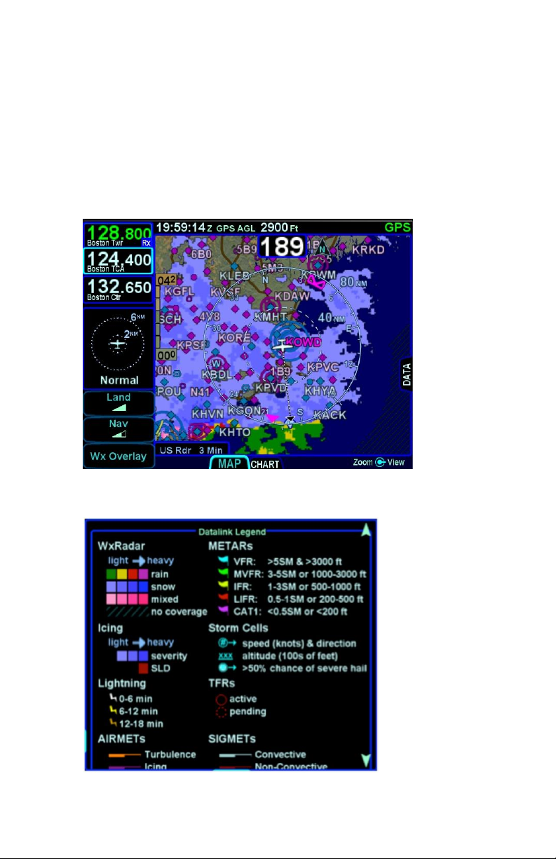
DATALINK RADAR
The Datalink radar is a composite image depicting precipitation
as seen by multiple ground-based weather radar sites. The
image is color-coded to show intensity levels and precipitation
types and is overlaid on top of any other map features, including
terrain alerting.
Datalink Precipitation Example
Weather Data Legend
3-14 Map Pages
Page 93
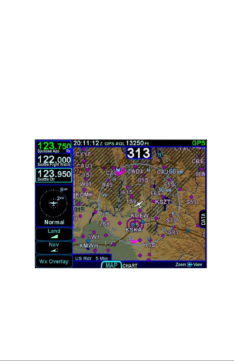
At large map ranges beyond 250nm from the aircraft, small areas
of high-intensity RADAR returns may not be displayed; instead,
larger areas of surrounding lower-intensity RADAR returns will be
shown.
Diagonal stripes show the Datalink radar data coverage area. In
normal operation the boundary follows the outline of the
Continental United States (CONUS). If, however, Datalink radar is
unavailable in a particular area for any reason, hatched lines
appear in that area. In the mountains and off the coast, hatched
lines may represent no coverage below 10,000 feet. If there are
radar returns in that region above 10,000 feet, the returns will be
displayed as “islands of precipitation” surrounded by the hatched
lines.
No Datalink Coverage Area Hatched Lines
Map Pages 3-15
Page 94
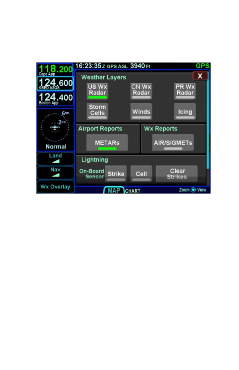
The “Wx Overlay” LSK on the map page brings up a control page
on which the layer combinations can be turned on or off.
Wx Overlay Selection
The options vary with the installed datalink device and
subscription level.
The Wx Overlay page is segmented into groupings of products.
One selection per grouping can be made and products selected
are indicated by a green lamp. The table below represents the
possible set of products available. Products that are not available
due to the device type or subscription level will not be displayed
as selectable choices.
3-16 Map Pages
Page 95

Weather Product Grouping
Title/Category
Possible Selections Within
the Grouping
Weather Layers
US Wx Radar
PR Wx Radar (Puerto Rico)
CN Wx Radar (Canada)
Storm Cells
Icing
Winds Aloft
Airport Reports
METARs
Weather Reports
AIR/SIGMETs
Lightning
Datalink
Sensor – Strike
Sensor – Cell
Sensor – Clear Strikes
Selections can be made by either touching the desired product or
by using the bottom right IFD knob.
Note that when there is an on-board lightning sensor selected
(Avidyne TWX670 Tactical Weather System or L3 WX500
Stormscope), the “Lightning” grouping will also include a “Clear
Strikes” function key.
Use the bottom right IFD knob to adjust altitude slices for icing
and wind products. Note that the IFD knob will only adjust the
weather product slice if the product is being displayed and is
valid; otherwise it still controls the map range and view.
Choices may include “METARS”, “AIR/SIGMETS”:
Map Pages 3-17
Page 96
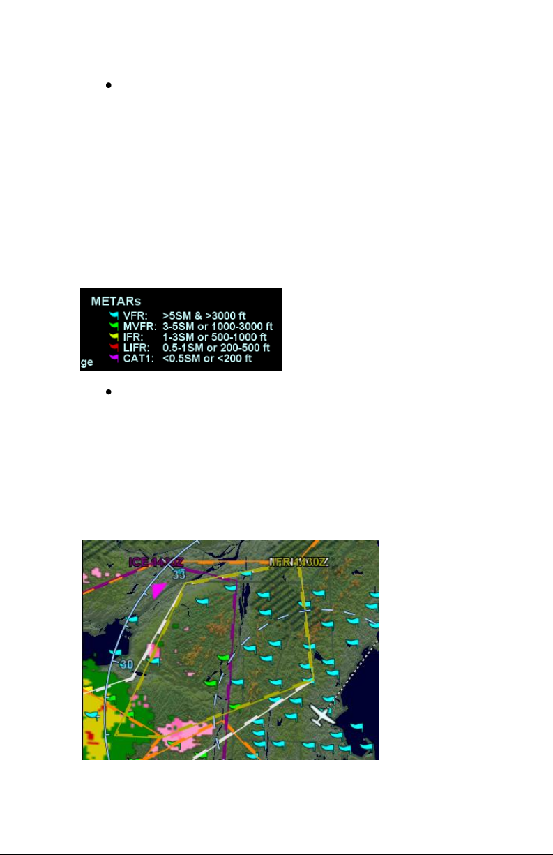
METARs – These are available in both text and
graphical formats and represent recent surface
weather observations. Text METARs are
presented on the “Info” tab of the “FMS” page. The
graphical METARs are color-coded flag symbols
that summarize a recent surface weather
observation and can appear as overlays on the
Map and embedded in the flight plan on the Flight
Plan tabs and Nearest tabs. These flags allow an
overview of general weather conditions in an area.
Graphical METAR Legend
AIRMETs and SIGMETs (US only) – These are
areas where the National Weather Service has
issued advisories for various types of hazardous
weather. They are depicted on the Map page
along with an abbreviated description of the
hazard, such as “ICE” (icing), “MTN” (mountain
obscuration), or “IFR” (instrument flight
conditions).
AIRMETs and SIGMETs Detail
3-18 Map Pages
Page 97
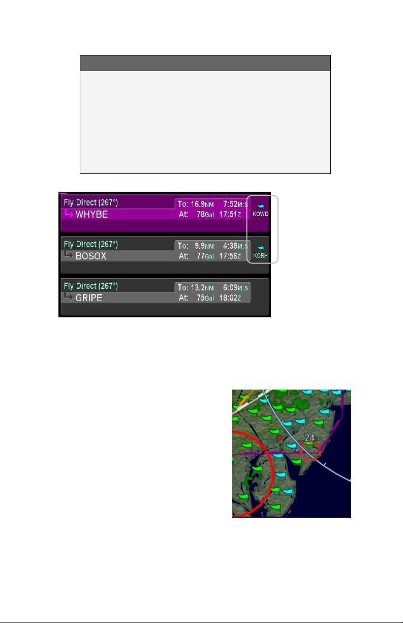
COOL FEATURE
METAR Flags in Flight Plan The right edge of
each leg in a flight plan presents a METAR flag for
the closest reporting station, if the station is different
from the previous leg’s station. The station for which
the METAR flag applies is decoded immediately
beneath the flag and may not be exactly the same
location as the leg itself.
TFRS
Active and Pending TFRs
TFR data is also transmitted via
Broadcast Datalink. Two types of
TFRs are depicted – active and
pending. Active TFRs are depicted
as solid red lines and Pending
TFRs are depicted as dashed red
lines, which become solid when
the TFR transition time rolls from
pending to active. TFR data cannot
be turned off.
Map Pages 3-19
Page 98
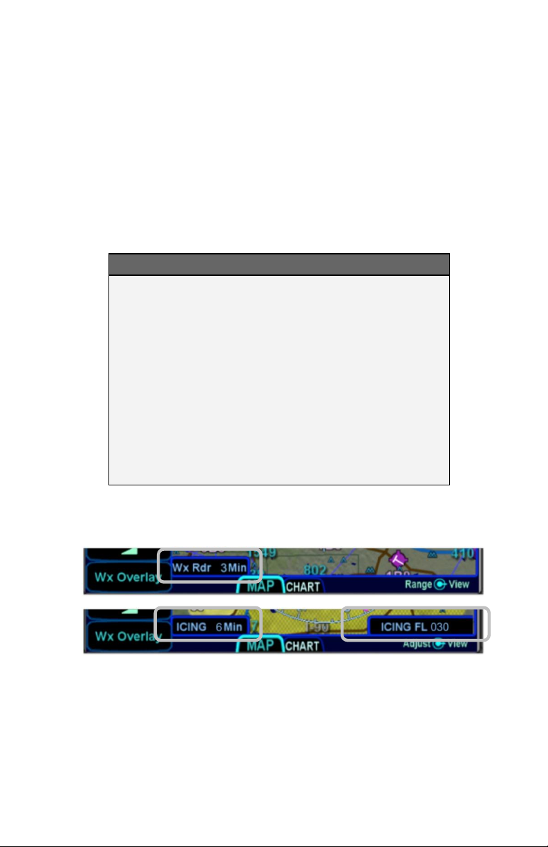
INDICATIONS OF DATA AGE
The multiple products transmitted as part of the Broadcast
Datalink service can arrive at different intervals. Two indicators at
the bottom corners of each map provide an easy-to-use indication
of data age. If a Datalink Icing product was selected for display
via the “Wx Overlay” key, the RADAR age is replaced by the age
of the icing altitude data currently being displayed; the icing
altitude slice currently displayed is shown in the bottom right
corner
NOTE
Datalink Data Position
The in-cockpit RADAR display depicts where the
weather WAS, not where it IS. The age indicator
does not show the age of the actual weather
conditions but rather the age of the mosaic image.
The actual weather conditions could be up to 15 to
20 minutes OLDER than the age indicated on the
display. Pilots should consider this potential delay
when using in-cockpit RADAR capabilities, as the
movement and/or intensification of weather could
adversely affect safety of flight.
Data Age: RADAR and Icing
3-20 Map Pages
Page 99
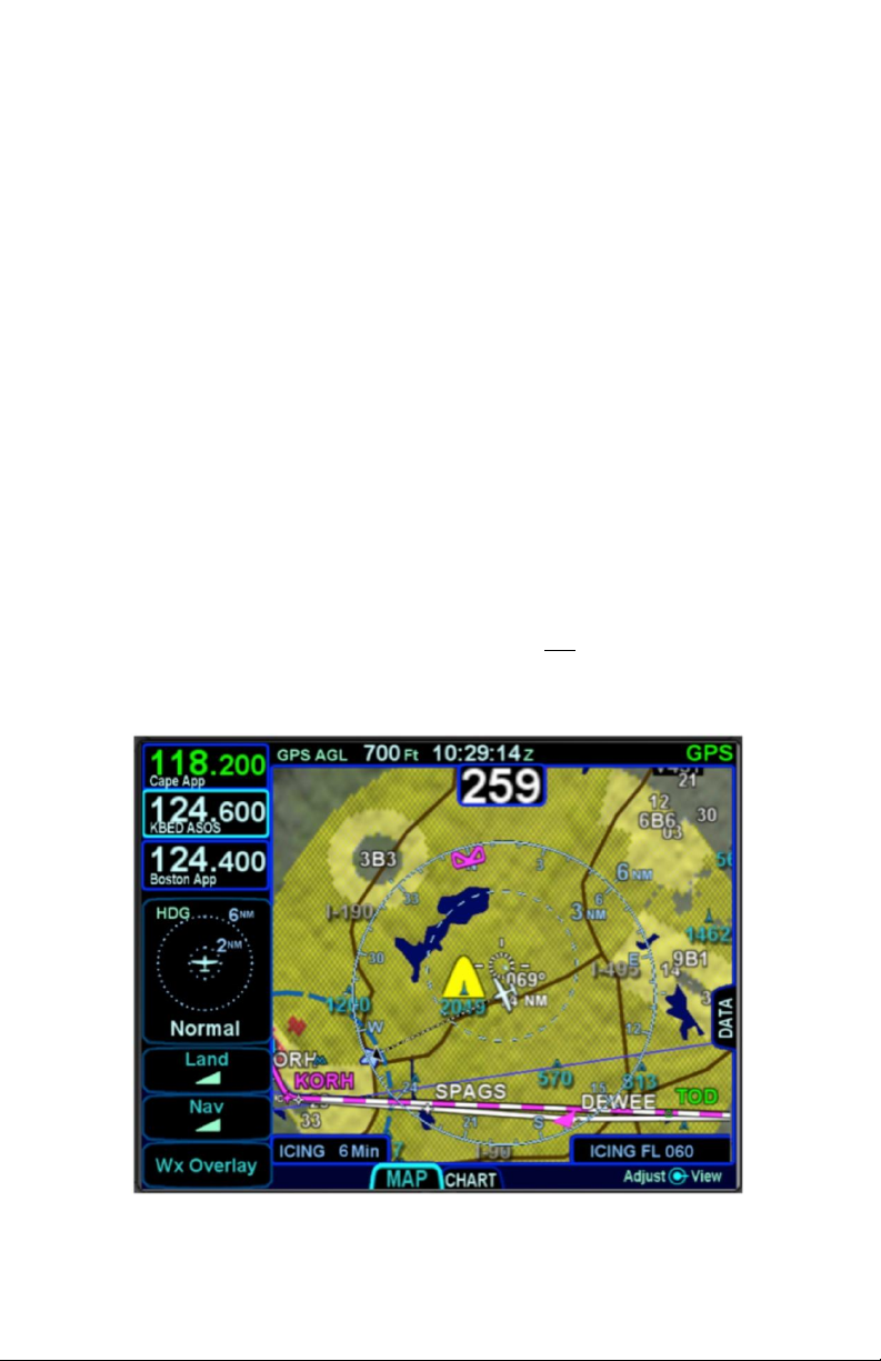
TERRAIN
Both Terrain Awareness (TA) and Forward Looking Terrain
Alerting (FLTA) are meant to serve as an aid to situational
awareness. They are intended to provide terrain and obstacle
awareness in the proximity of your aircraft. They are not meant to
be the sole means of terrain or obstacle avoidance.
Both TA and FLTA use a GPS-based MSL altitude and a 9 arcsec terrain database (WGS-84) to display a two dimensional
scene representing an “exocentric” look-down-from-above view.
The database is loaded on the IFD prior to shipping from the
factory, and is capable of being updated in the same manner as
other onboard databases, if necessary.
Both TA and FLTA compute height above terrain via GPS inputs
and are not a radio altimeter (RADALT).
TERRAIN AWARENESS (TA)
TA is for general situational awareness purposes and consists of
hatched terrain on any map page. TA will not generate a CAS
message or aural alert.
Terrain Awareness (TA)
Map Pages 3-21
Page 100

TA can be triggered by either terrain or database obstacles (e.g.
towers > 200’ AGL tall buildings, etc). Any terrain that is within a
10nm radius of aircraft position and between 100’ below aircraft
altitude and 1000’ below aircraft altitude will generate yellow
hatched indications on the map pages. Any terrain that is within a
10nm radius of the aircraft position and is 100’ below aircraft to
anything above aircraft altitude will generate red hatched
indications on the map pages.
Any obstacle in the database within a 5nm radius of the aircraft
position and whose top is within 2000’ vertically (above or below)
of the aircraft altitude will generate a cyan (blue) threat bubble
over the obstacle on the map pages. Obstacles inside a 3nm
radius of the aircraft position and whose top is between 100’
below aircraft altitude and 1000’ below aircraft altitude will
generate a yellow threat bubble over the obstacle. Obstacles
inside a 1.5nm radius of the aircraft position and whose top is
between 100’ below aircraft to anything above aircraft altitude will
generate a red threat bubble over the obstacle.
TA can be turned off via the “User Options” LSK of the SETUP
tab on the AUX page. When turned off, there is no terrain TA
display on the map pages for the individual IFD.
A rectangular suppression area exists for all runways in the FMS
database and user waypoints that have been designated to be an
airfield (see User Waypoints section earlier in this manual).
Terrain inside this suppression area will not generate any TA
indication. Dimensions of the TA runway suppression area are
0.25 nm laterally and 0.5 nm off each runway end. Airports with
no known runway orientation use a 1nm circular suppression
area. Obstacle threat bubbles can still appear inside the
suppression area.
Runway Suppression Area Depiction
3-22 Map Pages
 Loading...