


D 60
Avia D 60, D65, D70, D75, D 80 Owner's Manual
...
Dear driver,
This driver‘s manual was worked out for familiarising with operation and basic
maintenance of Your new AVIA truck and it should provide you with important
information from point of view of safe operation.
We recommend you to read it carefully and to follow instructions mentioned in it.
This way, you will gain pleasant and safe vehicle operation without problems.
For long-term vehicle life and certain operational reliability, it is necessary to have
vehicle repaired and maintained in some of our numerous authorised repair shops.
We would like to take advantage of this occasion to thank you for purchasing product
of AVIA company and assure you about our interest of your maximum
satisfaction..
We wish you to cover many thousands kilometres without accident.
AVIA ASHOK LEYLAND MOTORS s.r.o.
Praha - Letňany
Czech republic

Cargo truck
documentation
Owner's Manual
To become perfectly familiar with the
vehicle, it is necessary to study thoroughly Owner's manual and all additional instructions that are part of your
vehicle documentation (e.g. Owner's
Manual of automobile radio, certificate
of warranty for battery etc.).
Service Booklet
Documentation also contains Service
Booklet that contains:
n Identification data of vehicle
n Basic warranty conditions
n Warranty registration certificate
n Record of regular service inspec-
tions
n Labour activities, maintenance in-
tervals
n Record of car body inspections
n Specific Activities and maintenance
n Contract repair shops list
Components of equipment that are
designated with * are series mounted
only on certain models or they are
delivered only as exceptional equipment.
Warning!
n It is necessary to adhere at maximum rate the texts in this frame
(Warning!).
In the case of vehicle sale, it is necessary to hand over complete documentation.
ContentsInformation
Description
Compartment.......................................4
Keys......................................................6
Door......................................................6
Electric window winder*......................7
Instrument panel - indicators.............8
Indicator lamps....................................8
Combined switch over switch..........12
Cruise control ISBe...........................14
Diagnostic sockets............................17
Switchbox and steering lock...........18
Gear-shifting lever............................19
Steering-wheel inclination
adjustment.........................................19
Heating and ventilation.....................20
Air conditioner* ...................................... 22
Seats..................................................24
Headrests...........................................25
Safety belts........................................26
Rear view mirrors..............................28
Rear view mirror remote control*....28
Headlamps inclination adjustment..29
Cab interior illumination...................29
Digital clock*......................................30
Socket / cigarette lighter...................30
Sun visors..........................................30
Cup holder.........................................31
Ashtray...............................................31
2

Hanger, storage pocket....................31
Engine bonnet...................................32
Tools and equipment........................33
Hydraulic tilting of cab......................34
Instructions for cab tilting.................34
Chassis and cab................................36
Operating instructions
Inspection before drive.....................38
Running-in of vehicle........................38
Maintenance......................................38
Engine starting..................................39
During drive.......................................40
Engine stopping................................41
Engine for D family vehicles............42
Engine lubricating system................42
Turbocharger.....................................44
Fuel filter draining..............................45
Engine Cummins ISBe
- Tensioning of belts....................46,47
Engine Dwav D432
- Tensioning of belts....................48,49
Fuel tank............................................50
Fuel.....................................................50
Cooling system..................................51
Air cleaner.........................................52
Steering..............................................53
Gearbox.............................................54
Clutch.................................................56
Rear axle............................................57
Front axle...........................................57
Brake system.....................................58
Driving brake.....................................60
Brake lining inspection.....................62
Anti - Blocking - System...................64
Emergency brake..............................65
Parking brake....................................66
Washer and wiper.............................67
Tyres and wheels..............................68
Load transport...................................69
Electric equipment............................71
Battery attachment............................72
Battery................................................73
Alternator...........................................73
Headlamps and lamps - location....74
Care of vehicle..................................75
Malfunctions and their remedy
Engine................................................77
Electric equipment............................83
Monoblock hydraulic
power-assisted steering...................84
Brake..................................................84
Parking and spring-actuated brake.85
Vehicle towing and rescue...............86
Spare wheel carrier (N, L, E)...........87
Wheel chock (N, L, E)......................87
Spare wheel carrier (K).....................88
Wheel chock (K)................................88
Change of wheel...............................89
Change of bulbs................................90
Fuse box - cab...................................96
Fuse box - under battery
cover...................................................98
Starting by means of jumper
cables (D432)..................................100
Technical data
Engine..............................................102
Chassis............................................104
Brake................................................167
Dimensions of chassis-cabs..........108
Weights and weight on axles.........109
Tyre inflation....................................110
Truck circle diameter......................110
Gear ratios.......................................111
Maximum vehicle speed, climbing
performance....................................112
Electric equipment..........................113
Bulbs................................................114
Fuel consumption............................115
Service fluids...................................115
Vehicle identification number.........116
Labels...............................................117
3
D E S C R I P T I O N
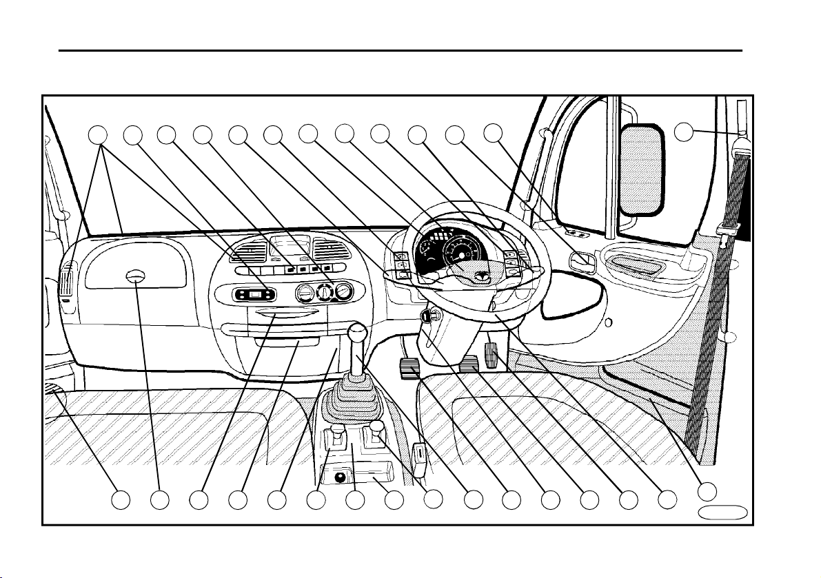
Compartment
12
25
20
FN0010
6
5
9
7
26 19 20 16 15 14 27 22 21 23 24
18
8
2 4
17
3
1 11
13
10
28
4

D E S C R I P T I O N
1 Combined change-over switch
-flash lamps
-position lamps
-low-beam headlamps
-high-beam headlamps
2 Combined change-over switch
-windscreen wiper control
-windscreen washer control
-exhaust brake
3 Controls
-front fog lamps
-rear fog lamps
4 Controls
-warning lamps
-rear-view mirror heating
5 Controls
-auxiliary drive
-differential lock
-truck superstructure illumination
-air conditioner
-cruise control (ISBe)
-cruise control - ON/OFF (ISBe)
-cruise control - SET/RESET (ISBe)
6 Measurement instruments and indicator lights
7 Digital clock
8 Heating control
9 Controlled air outlet
*
*
*
*
10Window winder
11Door open and lock
12Switchbox
13Parking brake
14Headlamp adjustment
15Rear-view mirror adjustment
16Gear-shift lever
17Horn
18Loudspeaker
19Ashtray
20Storage compartment
21Steering-wheel inclination control lever
22Clutch pedal
23Driving brake pedal
24Accelerator pedal
25Safety belt height adjustment
26Storage compartment (with cover *), fuse box
27Plug socket / cigarette lighter
28Plug socket 12 V
*
*
*
*
5
D E S C R I P T I O N
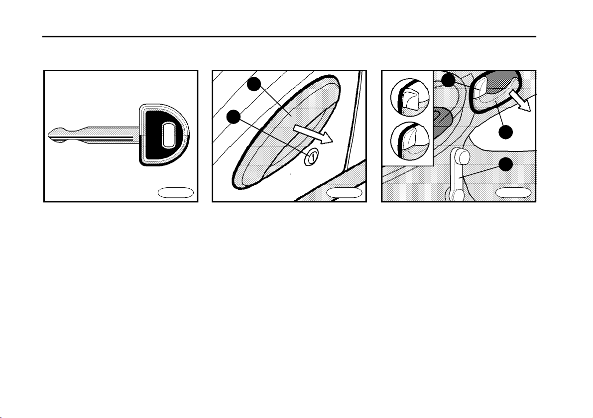
Keys
n Two keys are delivered - it is advised
to hide one of them outside vehicle as a
spare key.
n A label is fastened to keys where key
number is stamped. It is advised to hide
it outside vehicle and record the number.
n When vehicle is equipped with re-
cording speedometer, key for opening it
is delivered with vehicle.
Door
2
1
FN0030FN0020 FN0040
Exterior side
It is possible to lock and unlock both
doors by means of key from exterior
side. Key is inserted into lock (item 1).
Grasping the door handle (item 2) and
pulling outside results in door opening.
Unlocking - Insert the key, turn the key
90° counter clockwise and back to the
basic position, where the key can be
removed.
Locking - Insert the key, turn the key
slightly clockwise and back to the basic
position.
A
B
inner side
n (item 4)
A - Unlocked door
B - Locked door (Door locked this way
cannot be opened from both exterior
and inner side).
n Pulling lever (item3) door is opened
from inner side.
n Turning winder handle (item 5) re-
sults in window opening and vice versa.
4
3
5
6
D E S C R I P T I O N
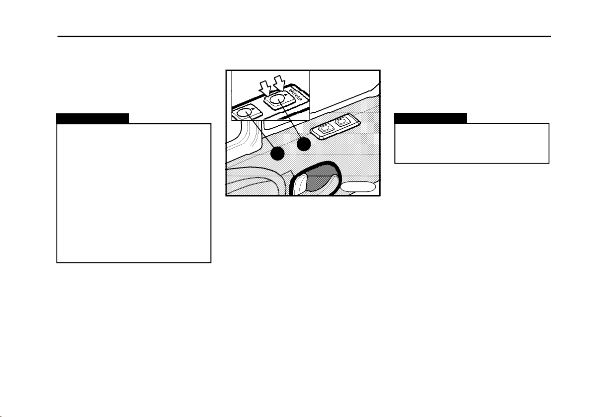
Central door lock
Central door lock is possible to lock or
unlock from driver‘s side both doors.
Warning!!
n Before leaving vehicle, always
remove ignition key from switchbox.
n It is necessary to take care of
closing rear and side doors of vantype truck and it is not permitted to
transport such cargo that disables proper door closing. If vantype truck damage occur due to
improper rear or side door closing
manufacturer exclude the truck
from warranty.
*
Electric window winder
1
2
n It is possible to wind windows only
when key is in position ON.
n Winding operates for the time of
pressing the button.
n Controls are placed on upper part of
doors.
n Both windows can be controlled from
the place of driver.
n Right side window can be controlled
from the place of front seat passenger.
n Control (item 1) - for window on driv-
er‘s side.
n Control (item 2) - for window on front
seat passenger‘s side.
*
FN0050
n Pressing of rocker switch front side
results in opening window, pressing the
other side window is closed.
Warning!
Take care of grip - mechanism is
able to create such force that could
result in injury.
7

D E S C R I P T I O N
Instrument panel - indicators
!D432
7
2
4
3
5
1 Recording speedometer
2 Engine revolution indicator
3 Pressure gauge of brake system
circuit I.
4 Pressure gauge of brake system
circuit II.
8
1
86
5 Fuel reserve indicator, reserve
6 Coolant temperature indicator,
7 Indicator lamp block I.
8 Indicator lamp block II.
9 Indicator lamp block III.
9
fuel indicator lamp
indicator lamp
FN0065
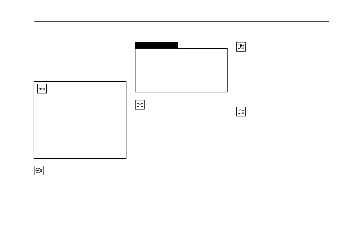
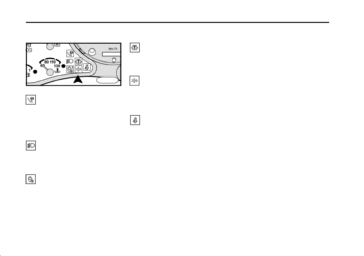
Indicator lamps
FN0070
Direction indicator lamp
n According to switched on flasher light
control, left or right indicator lamp flashes.
n Shorter time interval of flashing indi-
cates damage of flasher lamp bulb (it is
necessary to replace burnt bulb immediately).
High-beam headlamps
It glows when high-beam headlamps
are switched on.
Battery charging
n It glows when ignition is switched on,
after engine starting it should be
switched off.
D E S C R I P T I O N
n When indicator lamp is not switched
off or it starts glowing during driving, it is
necessary to stop vehicle and engine
and proceed according to chapter Mal-
functions and their repair.
Engine lubrication
(only D432)
n It glows when key is in position ON,
after engine starting it should be switched
off.
n When indicator lamp is not switched
off or it starts glowing (shine through)
during driving, it is necessary to stop
vehicle and engine and proceed according to chapter Malfunctions and their repair.
ABS (vehicle)
n It glows when key is in position ON
(for check of diode function), after short
time interval it should be switched off.
n When indicator lamp is not switched
off after short time interval or it starts
glowing during driving, it is necessary to
stop vehicle and proceed according to
chapter Malfunctions and their repair.
Warning!
The indicator lamp may start shine
throughin irregular intervals with
low light intensity. This shining
through does not indicate failure,
bur it is caused by continuous inspection of ABS control unit.
Brake system failure
n It glows when key is in position ON (for
check of diode), after short time interval
it should be switched off.
n When indicator lamp is not switched
off after short time interval or it starts
glowing during driving, it is necessary to
stop vehicle and proceed according to
chapter Malfunctions and their repair.
Parking brake
n It glows when parking brake is ap-
plied and when air pressure is lower.
n When it glows, it isn‘t possible to
move off or when it starts glowing during
driving, it is necessary to stop vehicle
and proceed according to chapter Mal-
functions and their repair.
Minimum level of braking
fluid
n It glows when key is in position ON (for
check of diode function), after short time
interval it should be switched off.
n When indicator lamp is not switched
off after short time interval or it starts
glowing during driving, it is necessary to
stop vehicle and proceed according to
chapter Malfunctions and their repair.
9
D E S C R I P T I O N
Minimum washer fluid
level
It glows in the case of washer fluid small
quantity.
*
FN0080
Brake lamp
n It glows when brake lamp bulb is
burnt.
n It is necessary to replace the faulty
bulb.
Low-beam headlamps
It glows when low-beam headlamps
are switched on.
Tilting of cab
It glows when the cab is improperly fixed
in rear support (it is necessary to repair
at once).
10
Air cleaner (clogged)
n It glows in case of clogged air filter.
n It ai necessary to replace air filter
element.
Safety belt
Necessity of safety belt fastening is
noticed.
*

D E S C R I P T I O N
FN0090
Exhaust brake
It glows when exhaust brake operates
(only D432, 422).
Differential lock
It glows when differential lock is activated.
Cargo area tipping
It glows when cargo area is tipped.
Auxiliary drive
It glows when auxiliary drive is activated.
Reverse lamp
It glows when reverse gear is engaged.
*
*
Flasher lights of trailer
n It glows when flasher lights are acti-
vated and trailer is towed.
n Shorter time interval of flashing indi-
cates damage of flasher lamp bulb (it is
necessary to replace burnt bulb immediately)
Engine – stop
ISBe
n It glows when switchbox is in posi-
tion "ON" (for checking operation)
After short time if must go out.
n It glows in a case of serious defect of
engine.
n If it will not go out after short interval,
or if it will glow during drive, you must
stop vehicle and follow chapter "Mal-
functions and their remedy".
Engine-warning.
ISBe
n It glows when switchbox is in posi-
tion "ON" (for checking operation)
After short time if must go out.
n It glows in a case of mistake or defect
of engine component.
If it will not go out after short interval or if
*
it will glow during drive, you must stop
vehicle and follow chapter "Malfunc-
tions and their remedy".
Glowing plugs
It glows after turning ignition key in
switchbox to position „ON“. For ISBe
only at lower evoironmental temperatures. After switching off, it is possible to
start engine.
Engine – maintenance
ISBe
n It glows when the switchbox is in
position ”ON” (for checking operation).
After short time if must go out.
n It glows in a case of necessary main-
tenance (exchange of oil.
n If it will not go out after short interval,
or if it flickers or if it will glow during drive,
you must stop vehicle and follow chapter "Malfunctions and their remedy".
11
D E S C R I P T I O N
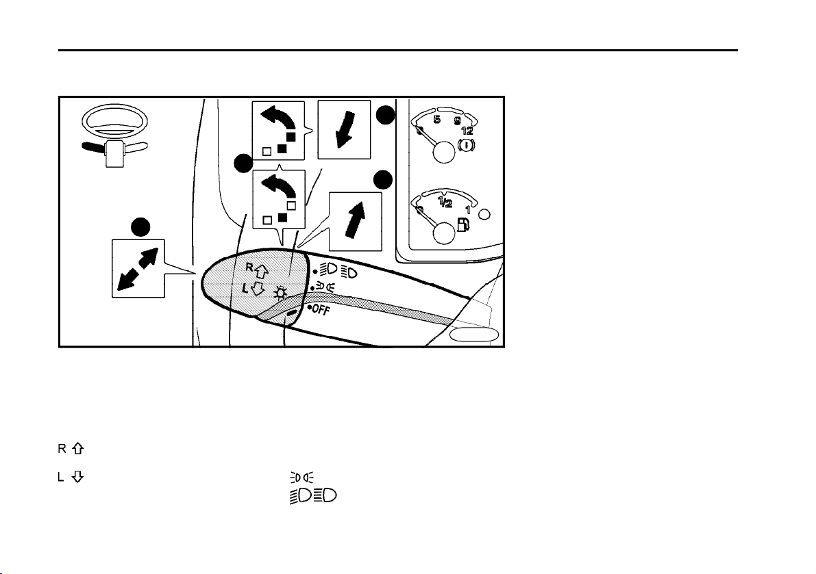
Combined switch over switch
2
1
1 Flasher lamps
Flasher lamps are active when key is in
position ON. They are set by vertical
movement, perpendicular to steering
wheel centreline.
right flasher lamps - shift control
lever upward
left flasher lamps - shift control
lever downward
12
2 Position lamps and low beam
headlamps
They are switched on by turning tip of
control lever.
Lamps that have their symbol aligned
with notch shine
OFF Lamps are switched off
3
4
FN0100
Position lamps are switched on
Low beam headlamps are
switched on (alternatively
main beam headlamps)
n Audible signal indicates open doors
and burning lights.
3Low and high beam switch
over
n To switch on high beam headlamp,
press control lever in direction from steering wheel (high beam is indicated by
indicator lamp).
n Switching over is performed by pull-
ing control lever to original position.
4 Headlamp flasher
n Pull slightly control lever to steering
wheel (high beam indicator lamp are
switched on).
n Lamps glow for the time of holding
the lever.
5 Windscreen washer
n Wiper and washer are active when
key is in position ON.
n Washer is switched on by pressing
to the end of control lever. Washer pump
is activated for the time of pressing the
switch.
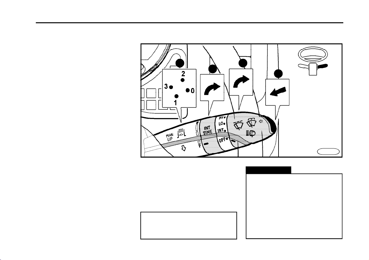
6 Windscreen wiper
It is switched on by turning the end of
control lever:
OFF Wiper is switched off
INT Position for selection of pulsating
wiper time interval (in this position
it is possible to select arbitrary in
terval that is gradually controlled
by rotary ring (item 7).
LO Slow and uninterrupted wiping.
HI Fast and uninterrupted wiping.
7 Selector of pulsating wiping
interval
Interval is the shortest in position F,
turning of ring increases the interval.
D E S C R I P T I O N
8
7
6
5
FN0110
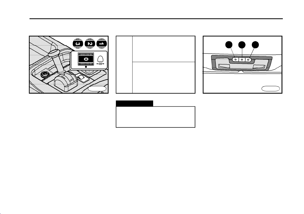
8 Exhaust brake
Position 0 - push combined switch in
direction from driver forwards and downwards - the engine brake is switched off.
Position 1 -pull the switch in direction to
driver backwards and downwards - the
engine brake is is on during operation
of break pedal.
Position 2 - push the switch in direction
from driver forwards andupwards - the
engine brake is on after too sening
*
accelerator pedal (at revolutions higher
than idle speed).
Position 3 - pull the switch in direction to
driver backwards and upwards - the
engine brake is on after loosening accelerator pedal or during operation of
break pedal as well.
It is recommended to engage &
disengage the engine brake at least
once a week - engine brake service-life is extended in this way.
Warning!
n By actuating the accelerator pedal - the engine brake is disengaged
automatically from its action.
n Action of the engine brake is
signalled by a warning lamp.
n Signalling by the warning lamp
depends on action of the engine
brake, not at all on the switch position.
13

D E S C R I P T I O N
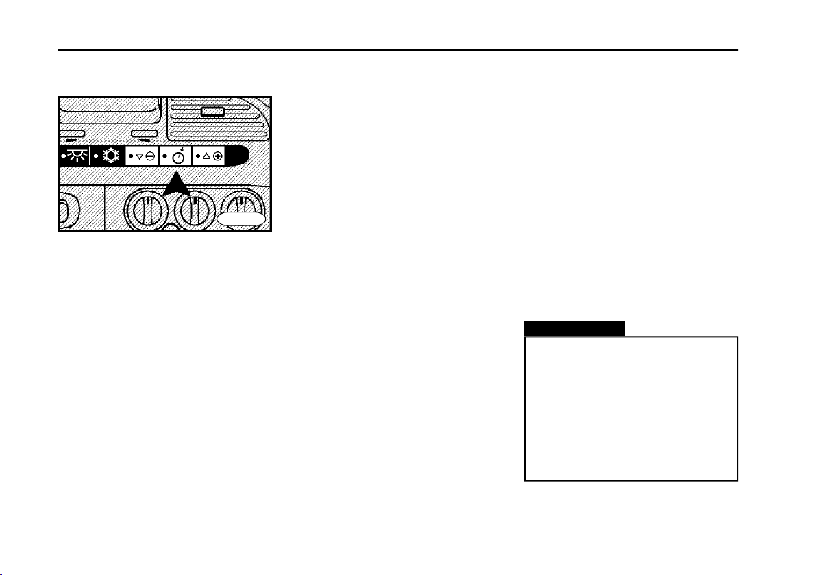
Controls
1
2
1Auxiliary drive
n It is engaged when vehicle is motion-
less when engine speed is low for about
6s.
n When engine is running, it is neces-
sary to press clutch pedal.
n Engaged drive is indicated by indica-
tor lamp.
8
7
*
11109
6
5
2Differential lock engaging
n It is engaged when vehicle is motion-
less when engine speed is low for about
6s.
n Use only for the time necessary to
overcome more severe driving conditions.
n Engaged lock is indicated by indica-
tor lamp.
3
4
FN0125
Warning!
It is possible to engage items 1. and
2. only under air pressure higher
than 0.55 MPa - otherwise engaging
isn‘t reliable.
It is recommended to engage &
disengage the differential lock at
least once a week - differential lock
service-life is extended in this way
(it is effective especially for the
EATON final drives).
3 Warning lights
n Indicated by lamp, placed in control.
n It is possible to switch on even when
ignition is switched off.
4Outside rear-view mirror
heating
It is indicated by bulb in control.
Warning!
Allow heating to operate for needful time.
14
D E S C R I P T I O N
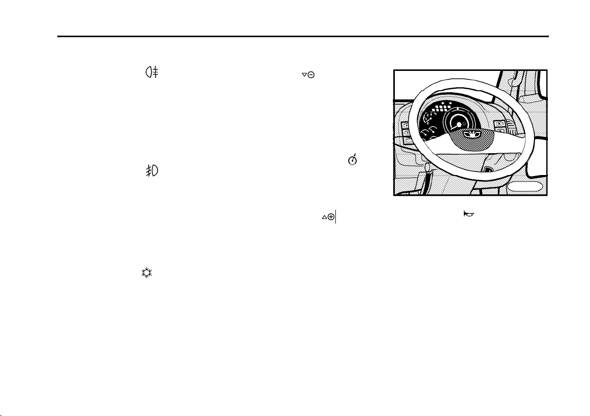
5Rear fog lamps
n It is possible to switch rear fog lamps
on only when low beam, high beam or
front fog lamps are switched on.
n Owing to dazzle effect they are al-
lowed to use under fog, heavy rain and
snow conditions.
n It is indicated by bulb in control.
6Front fog lamps
n Fog lamps shine when position
lamps and low or high beam lamps are
switched on.
n It is indicated by bulb in control.
7Cargo space illumination
It is indicated by bulb in control.
8Air conditioner
n Cooling device operates only when
engine is running.
n Air conditioner does not operate, when
rotary switch of blower is in off position.
n Signalled by bulb in control.
*
*
9Reset / coast
ISBe
n It resets speed, adjusted on cruise
control.
n It is possible by this switch to reduce
revolution of engine during drive or with
P.T.O..
10 Cruise control switch
ISBe
n It is used for switch ON cruise control
or P.T.O..
11 Set / accelerate
ISBe
n It sets real speed to memory of cruise
control.
It is possible to increase revolution of
engine during driving or using P.T.O..
n During diagnostic testing, of switch
pressing will set next defect code.
FN0135
Acoustic horn
Control of acoustic horn is located in the
centre of steering wheel.
15
D E S C R I P T I O N
Cruise control
ISBe
FN0136
n Cruise control keeps adjusted speed
(engine revolution during driving or using P.T.O.) without using accelerator pedal.
n Three control elements in central
panel of dashboard are used.
n Cruise control begins operation
above approx. 48 km/h, using P.T.O. up
to 48 km/h (optional).
Adjustment of cruise control
n Press ”Cruise control” switch ON.
n Reach required speed and than
press shortly switch ”Set/accelerate”:
Now the speed is adjusted in memory
and the engine will keep this speed
without using accelerator pedal.
n It is possible to increase speed by
accelerator pedal . After releasing pedal, the speed of the vehicle will be influenced again by the cruise control (of
course, ”Cruise control (main)” switch
must be in the ON position.
n All functions will be cancelled after
actuating clutch pedal, brake pedal or
by switching ”Cruise control” switch to
OFF position. Operation of cruise control will be restored by short pressing of
switch ”Reset / coast” it means that it is
not necessary to adjust cruise control
again.
Adjustment of P.T.O. revolutions
at parking of vehicle.
n Adjustment of P.T.O. revolutions when
the truck is at stand still.
n Press switch "Cruise control".
n Increase revolutions by pressing
"Set / accelerate" switch (range of adjustable revolutions is 950 - 3000 rev./
min.). By holding switch, revolutions in
crease continuously. By pressing
switch, revolutions increasle by steps
(approx. 25 rev./min.).
n By pressing switch "Reset / coast",
1200 rev./min. will be set automatically.
Warning!
n If cruise control is not used,
”Cruise control” switch must be in
the OFF position.
n Speed of the vehicle can be influenced by climbing or by weight of
load . Therefore use cruise control
only during driving on level ground
or when differences of landscape
elevation are only small.
16
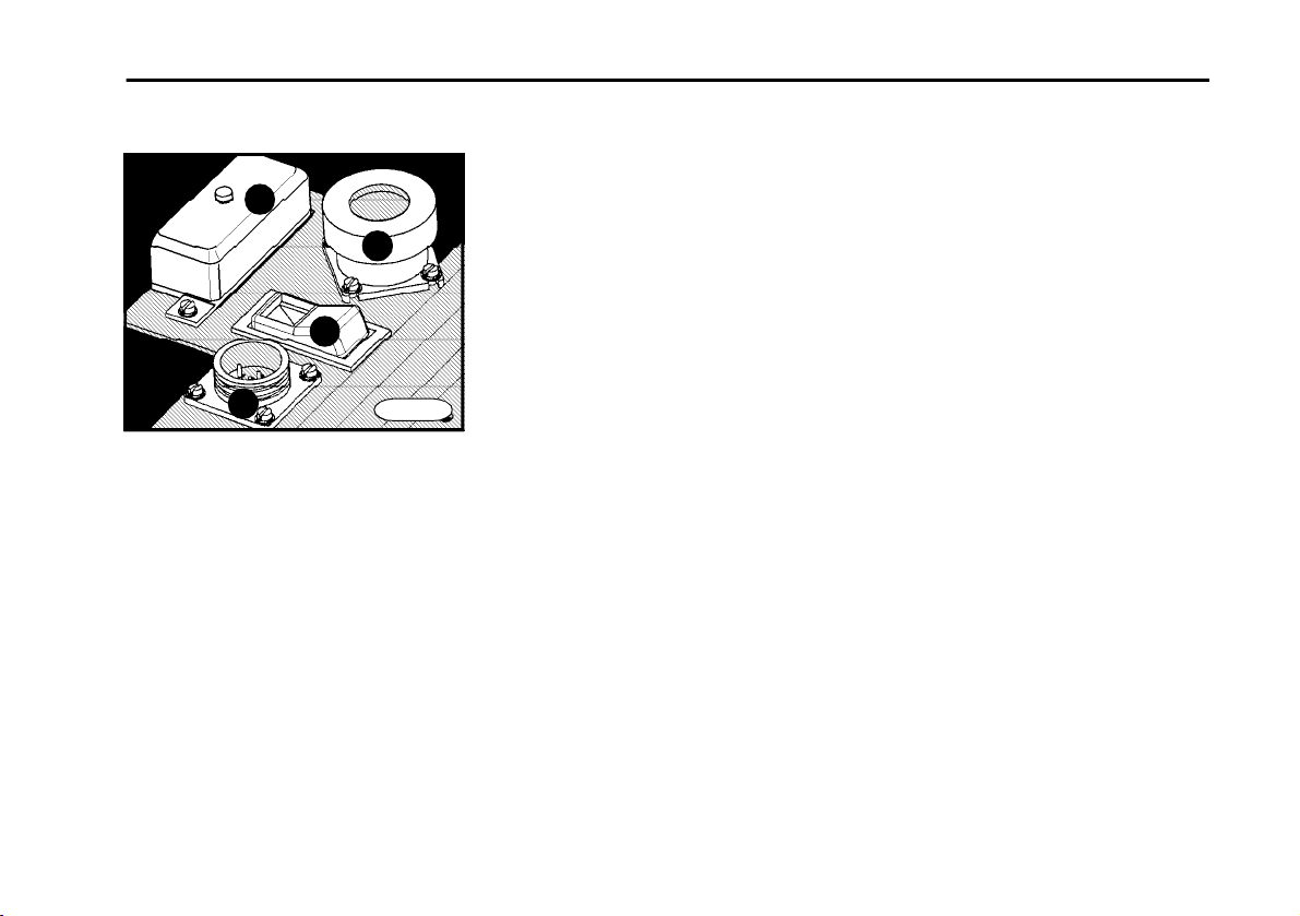
Diagnostic sockets
4
3
D E S C R I P T I O N
1 Socket for ABS diagnostics
2 Socket for engine diagnostics
ISBe
2
3 Switch of engine diagnostics
ISBe
4 Fuse box for voltage changer
(fuses 2x 5A)
1
n Diagnostic sockets are placed un-
der package compartment in the instrument panel.
n Access is facilitated after removing
bottom of the package compartment
that is loosened by rotating two turnable
holders (rotation direction is marked on
the cover).
FN0132
17
D E S C R I P T I O N
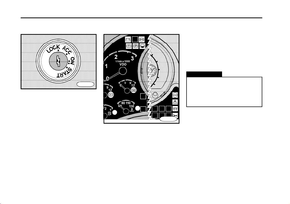
Switchbox and steering lock
FN0140
Switching positions
n Position "LOCK"
Only in this position, it is possible to
insert and remove ignition key. Merely
recording speedometer, electric clock
or radio are connected. Only in this position, steering wheel shaft is automatically locked.
n Position "ACC"
Steering is unlocked, electric circuits
that are connected through switchbox
are without voltage. After switching over
from position "ON" to this position, en-
gine is stopped.
18
FN015cu
n Position "ON"
Following indicator lamps glow: (see
fig.)–battery charging,
only D432)
, brake system malfunction,
(engine lubrication
parking brake, minimum level of brake
liquid, glowing plugs, ABS, coolant temperature, fuel reserve. In the case of
engine ISBe, also following indicator
lamps glow:engine–stop, engine–
warning, engine–maintenance. After few
seconds,only following indicator lamps
remain to glow: battery charging,
lubrication only D432)
, possibly glowing
(engine
plugs. After glowing indicator lamp will
go out, engine is ready to start. Electrical
circuits, connected to switchbox, are
under voltage.
Warning!
If after short time any indicator
lamp, which is tested only itself,
will glow, it is necessary to follow
Chapter "Malfunction and their remedy".
n Position "START"
The engine can start only if gears are
disengaged, without using accelerator
pedal. Position is not locked. For restarting, turn back ignition key to position "ACC" - that prevents from restarting of running engine that could result in
starter motor damage.
Warning!
n Function of switchbox is assured
when battery master switch is on.
n Do not switch off battery master
switch or disconnect battery terminals when engine is running to
prevent alternator or some electric device damage.
D E S C R I P T I O N
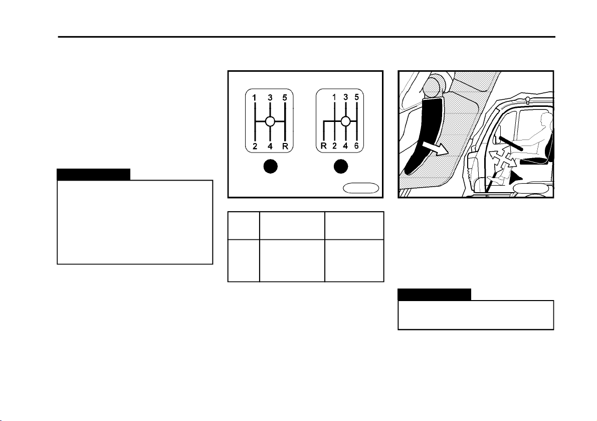
Gear-shifting lever Steering-wheel inclina-
tion adjustment
1
Position Gearbox type Number of
1 ZF S5-42 5
2 ZF 6 S 850 6
2
gears
FN0160
FN0170
n Release steering wheel pulling con-
trol lever in direction to yourself and
adjust steering wheel position to required position.
n After adjustment, press control lever
in forward direction up to stop.
Gear changing is performed mechanically by means of gear shifting lever,
when clutch pedal is depressed.
Warning!
To adjust steering wheel during
drive isn‘t acceptable.
19
D E S C R I P T I O N
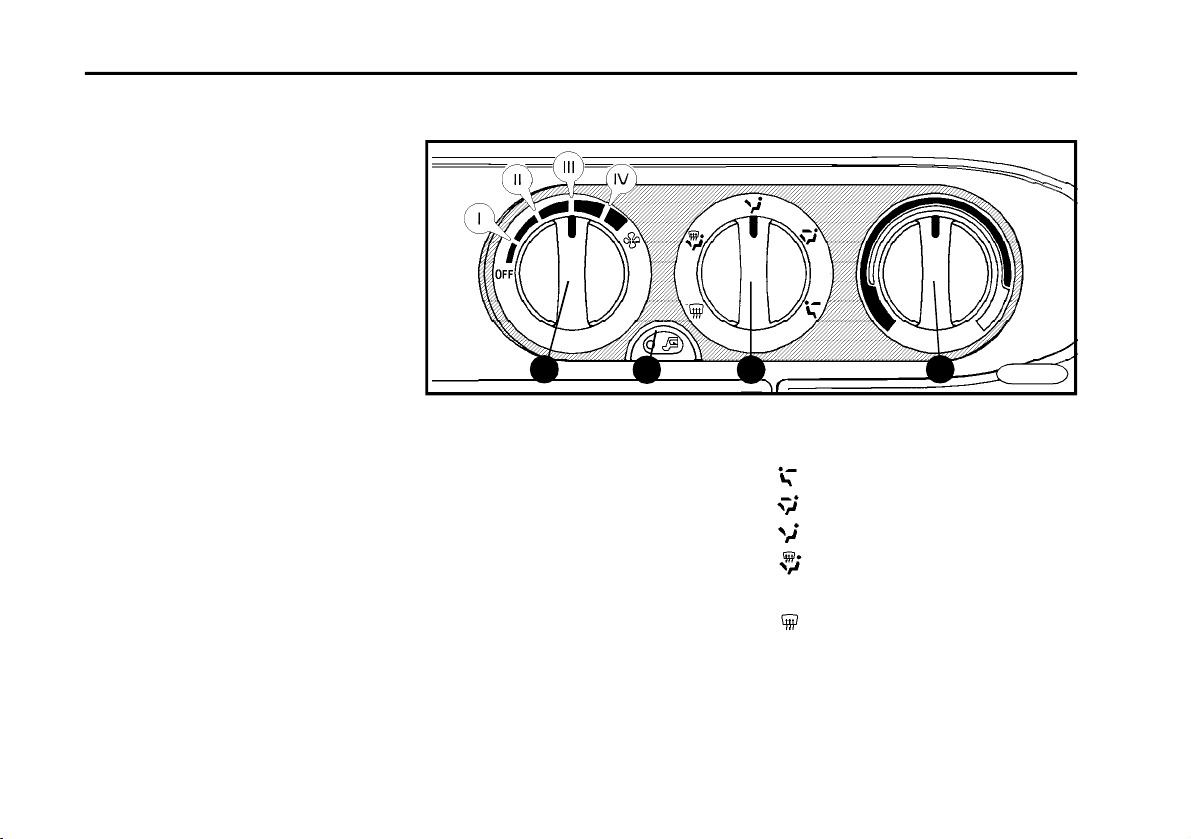
Heating and ventilation
n The truck cabin is heated by a hot
water heating. It is possible to use it
after coolant is heated up in the
cooling&heating water circuit after the
engine is started.
n Heating is controlled and regulated
by turning of heating controls located
on instrument panel.
n Heating valve control (item 3) regu-
lates quantity of water flowing through
heating element and so temperature
of outlet air (when turning to red field,
hot air is produced and vice versa).
n Control (item 1) regulates fan speed
and so quantity of air that comes through
the system. Speed is adjustable in four
steps.
n Air flow direction control (item 2) en-
ables to select direction of air outlet
(The way of cab heating).
n Button (item 4) switches on or off
mode of circulating air in cab.
n Rib inclination (item 5) of air outlet
can change angle of air flow. Quantity of
air flowing from individual vent hole can
be controlled by wheels (item 6).
24
1Heating fan control
2Air flow direction control
to heads of crew
to legs and heads of crew
to legs of crew
to legs, windscreen and side
windows
to windscreen and side windows
3Heating valve control - temperature
regulation of outlet air.
4Mode of circulating air.
31
FN0185
20

D E S C R I P T I O N
5
6
Removing hoarfrost and bedewed windows
n (item 1) up to stop to position IV.
n (item 3) to the left up to stop.
n (item 2) turn to position .
n Close vent holes by control wheels.
Removing icing from
windscreen
n (item 1) up to stop to position IV.
n (item 3) to the left up to stop.
n (item 2) turn to position .
n Switch mode of air circulation,
n Close vent holes by control wheels.
5
5
Maintaining windows in status
without bedew under higher
humidity.
When windows are constantly bedewed (e.g. in rain), it is necessary:
n (item 1) to position II or III.
n (item 2) turn to position .
n (item 3) if necessary to area of heating.
Ventilation
n (item 1) to required position.
n (item 3) to the right stop.
n (item 2) turn to position
Pleasant heating
n (item 1) to position II or III.
5
66
FN0195
n (item 3) to required heating output.
n (item 2) turn to position .
Maximum heating
n (item 1) to position IV.
n (item 2) turn to position
n (item 3) to the left up to stop.
n Switch on mode of circulating air.
Warning!
Heating output is dependent on coolant temperature. Maximum heating output is obtained after heating
engine to operation temperature.
21

D E S C R I P T I O N
Air conditioner*
6
7
n Air conditioner is combined cooling
and heating equipment.
n Cooling unit of air conditioner cools
air and removes moisture out of air.
n Cooling device operates only when
engine is running.
6 7
5
2
Controls
n Air conditioner is switched on (off) by
control (item 1) designated with symbol (indicated by bulb located in
control). n Air conditioner doesn‘t
operate when rotary switch is in off
position.
n Control of heating valve (item 4) reg-
ulates temperature of inlet air (turning
to red field - hot air and vice versa). It is
possible to use it even when air conditioner is switched on.
n Control (item 2) regulates fan speed
and so quantity of air passed through
2
3
6
4
system. Speed of air flow is adjustable
in four steps.
n Control of air flow direction (item 2)
enables to select direction of air outlet
(way of cab heating)
n Button (item 5) switches on (off)
mode of air circulation in cab (indicated
by bulb located in control).
n Travel of air outlet fins (item 6) can
change angle of air flow. Air quantities
regulated by wheels (item 7).
7
FN0195
6
22

Optimal cooling
n (item 1) to requested position (posi-
tions II and III are optimal)
n (item 3) up to stop to the right, tem-
perature can be regulated according to
need by means of turning to the left.
n (item 2) turn to position
n Press switch with symbol (bulb
in control glows)
n In this mode, exterior air is sucked
and cooled.
2
Maximum cooling
n Close all windows
n (item 1) to position IV
n (item 3) up to stop to the right
n (item 2) turn to position
n Press control with symbol . (bulb
in control starts to glow)
n Switch mode of air circulation on
31
FN0185
D E S C R I P T I O N
Warning!
It isn‘t recommended to smoke
when air circulation in cab mode is
on.
Warning!
n If vehicle is parked on direct
sun, open windows before switching on of air conditioner.
n It is recommended to operate
air conditioner at least once a
week - it extends life of air conditioner.
23
D E S C R I P T I O N
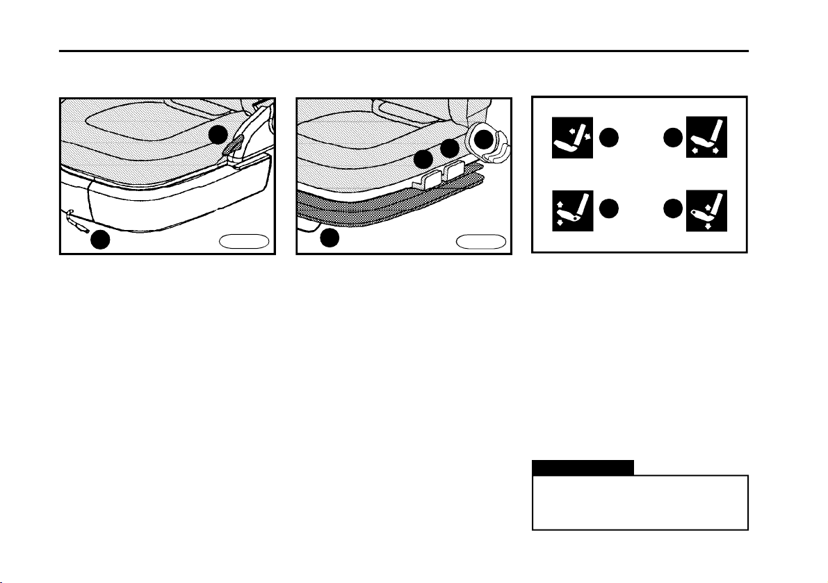
Seats
1
2
Adjustment of seat backrest
inclination (a)
Tilting of seat backrest backwards is
performed by control lever (item 1) lifting and pressing to backrest in backward direction.Tilting of seat backrest
forwards is performed by control lever
(item 1) lifting and slight pressing to
backrest in backward direction and consequential release of backrest that automatically tilts forwards. The backrest
is secured by releasing the small lever.
Adjustment in longitudinal
direction (b)
n Longitudinal shift is released by pull-
ing control lever (item 2) upwards and
24
FN0200
1
4
3
2
then it is possible to adjust seat to
required position. The seat is released
by releasing the small lever.
n Seat should be adjusted so that driv-
er can safely control pedals.
Adjustment of seat squab
incline (c) and height (d) on
the driver´s pneumatically
sprung seat
n Front part of seat is adjustable by
lever (item 3).
n Rear part of seat is adjustable by
lever (item 4).
n Regulation in upward direction is
performed in released status.
*
FN0210
a b
c d
Proper adjustment of seats
n Backrest should be adjusted so that
driver could hold steering wheel in its
highest point by slightly wrinkled hands.
n Quick and safe manipulation with
necessary controls that are important
for driving must be secured.
n It must result in free holding of body
for maximal protective effect of safety
belts.
Warning!
For precautionary reasons, driver‘s seat is allowed to adjust only
when vehicle stops.

Headrests
FN0220
n Headrests are height-adjustable.
n For height adjustment of headrest,
press stop in direction to back wall.
n Adjust headrest so that its position
recommends to physical dimensions
of driver‘s figure.
D E S C R I P T I O N
Warning!
n Good adjustment of headrest effectively supports nape during rear
impact.
n For precautionary reasons, driver‘s headrest is allowed to adjust
only when vehicle stops.
25
D E S C R I P T I O N
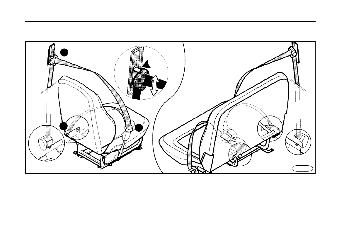
Safety belts
FN0230
n The truck cabin is equipped with pre-
loaded three-point seat belts of outward seats.
26
n The middle seat features two-point
seat belt with mechanical adjustment.
n Safety belts are used as passenger
protection in case of accident.
n Safety belts must be used during
each drive - even in city traffic.
D E S C R I P T I O N
Use of safety belts
n Necessity to use safety belts is sig-
nalled by relevant indicator lamp*.
n Take safety belt catch and slowly
draw over thorax and pelvis.
n The belt must fit tightly to centre of
shoulder and pelvis.
n When the belt is during pulling out
locked, release it and let it wind back
and than pull it out again.
n Insert catch into belt lock that corre-
sponds to the seat.The belt is properly
fixed after snap into lock.
n The belt is released after pressing
red lock stopper.
Height-adjustment of safety
belts
*
n Due to height adjustable upper bear-
ing of belt, it is possible to adapt belt
best way to physical dimensions of figure.
n For height-adjustment, press button
in downward direction, turn upper belt
bearing in direction to yourself (upwards) and adjust to requested position.
Warning!
n Belt must not lie over rigid or
easy fractured objects that could
be e.g. in your clothing, in pockets.
n Safety belts that went through
accident or they are damaged must
be unconditionally replaced by new
belts.
n Take care of the belt not to be
twisted and to lie over pelvis and at
least over soft parts of body.
n Maximum effect can be reached
with proper seating position in cab.
n One seat belt is allowed to bind
only one person.
n Maintain safety belts clean (dirt
influences on winding mechanism).
For cleaning, it is recommended to
use soft soap solution.
n When safety belt is damaged,
let it replaced.
27

D E S C R I P T I O N
Rear view mirrors
n Vehicles are equipped with heated
rear view mirrors.
n Heating is switched on by control
that is placed on instrument panel and
it is indicated by indicator lamp placed
directly on control.
n Heating is used for necessary time.
Warning!
n For safety reasons, mirrors
must be adjusted before drive.
n It is necessary to pay attention
of judgement about size and distance of vehicle or another objects
that are visible in side convex mirror (objects look smaller and they
are displayed more distant then it
is in reality.
Rear view mirror remote
control
n Turn control to select between left
and right mirror.
To the left - left mirror - position A.
To the right - right mirror - position B.
n Requested position of mirror is
reached by skewing of four-position
control.
*
A
B
FN0240
28
D E S C R I P T I O N
Headlamps inclination adjustment
K 1 2 3
N 1 2 3
L 1 2
FN0255 FN0260
n Regulation wheel changes head-
lamp inclination.
n Basic adjustment is performed with
vehicle without cargo load (notch of
adjustment control aligned with nought).
n Payloads of given version are men-
tioned in table Weights and weight on
axles.
E 1 2
Warning!
It is obligatory for driver to adjust
headlamps inclination according
to actual vehicle load with cargo.
Percentage of payload
30% 50% 70% 100%
Cab interior illumination
1
2 3
n Ceiling light bulbs are switched on
by controls located directly on lamp.
n Controls (item1) and (item 2) switch
on (off) illumination of driver‘s side.
n Control (item 3) switches on (off)
illumination of front-seat passenger ‘s
side.
29
D E S C R I P T I O N
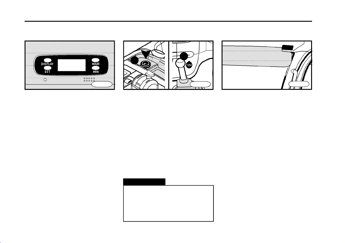
Digital clock
n Button „HOUR“ adjusts individual
hours.
n Button „MIN“ adjusts individual min-
utes.
n Button „SET“ clears minutes to whole
hours.
n Button „DISPLAY“ illuminates clock
when switchbox is in position „LOCK“.
Clock is illuminated for time of button
holding.
*
FN0270
Socket / cigarette
lighter
A
n Socket (pos. A) may be used for con-
nection of cigarette lighter or additional
current consumer having 24V supply.
To use the socket * (pos. B) for current
consumers having 12 V supply
n Cigarette lighter is switched on by
pressing to extension piece. After of
heating of heating element in lighter,
extension piece springs up. Remove
heated lighter and use it immediately
(element quickly looses heat energy).
Warning!
n During manipulation with lighter
take a good care of burn.
n When lighter does not spring up
after about 30 seconds, it is necessary
to remove it to prevent heat damage.
B
FN0280
Sun visors
FN0295
n Sun visors are located above wind-
screen in ceiling panel.
n They can be lowered according to
need.
n Adjust sun visors to protect against
bedazzlement.
30
 Loading...