


AVerMedia®
NV 3000/5000/6000(EXP)/7000H
Digital Video Recording System
User Manual
Version 7.1(SP1)
FCC NOTICE
This device has been tested and found to comply with the limits for a Class A digital device, pursuant to Part 15 of the FCC Rules. These limits are designed to provide reasonable protection against harmful interference in a commercial, industrial or business environment. This equipment can generate, use and radiate radio frequency energy and, if not installed and used in accordance with the instruction, may cause harmful interference to radio communications. However, there is no guarantee that interference will not occur in a particular installation. If this equipment does cause harmful interference to radio or television reception, which can be determined by turning the equipment off and on, the user is encouraged to try to correct the interference by one or more of the following measures:
•Reorient or relocate the receiving antenna.
•Increase the separation between the equipment and receiver.
•Connect the equipment into an outlet on a circuit different from that to which the receiver is connected.
•Consult the dealer or an experienced radio/TV technician for help.
This device complies with Part 15 of the FCC Rules. Operation is subject to the following two conditions: (1) this device may not cause harmful interference, and
(2) this device must accept any interference received, including interference that may cause undesired operation.
CAUTION ON MODIFICATIONS
To comply with the limits for the Class A digital device, pursuant to Part 15 of the FCC Rules, this device must be installed in computer equipment certified to comply with the Class A limits. All cables used to connect the computer and peripherals must be shielded and grounded. Operation with non-certified computers or non-shielded cables may result in interference to radio or television reception.
Any changes or modifications not expressly approved by the grantee of this device could void the user's authority to operate the equipment.
CE NOTICE
This product is conformity with the protection requirements of EU Council Directives 89/336/EEC amended by 92/31/EEC on the laws of the Member States relating to electromagnetic compatibility.
Warning- This is a Class A product. In a domestic environment this product may cause radio interference in which case the user may be required to take adequate measures to correct this interference.
DISCLAIMER
No warranty or representation, either expressed or implied, is made with respect to the contents of this documentation, its quality, performance, merchantability, or fitness for a particular purpose. Information presented in this documentation has been carefully checked for reliability; however, no responsibility is assumed for inaccuracies. The information contained in this documentation is subject to change without notice.

In no event will AVerMedia® be liable for direct, indirect, special, incidental, or consequential damages arising out of the use or inability to use this product or documentation, even if advised of the possibility of such damages.
TRADEMARKS
AVerMedia® is a trademark of AVerMedia® TECHNOLOGIES, Inc. IBM PC is a registered trademark of International Business Machines Corporation. Microsoft is a registered trademark and Windows is a trademark of Microsoft Corporation. All other products or corporate names mentioned in this documentation are for identification and explanation purposes only, and may be trademarks or registered trademarks of their respective owners.
COPYRIGHT
2007 by AVerMedia® TECHNOLOGIES, Inc. All rights reserved. No part of this publication may be reproduced, transmitted, transcribed, stored in a retrieval system, or translated into any language in any form by any means without the written permission of AVerMedia® TECHNOLOGIES, Inc.
Following information is only for EU-member states:
The use of the symbol indicates that this product may not be treated as household waste. By ensuring this product is disposed of correctly, you will help prevent potential negative consequences for the environment and human health, which could otherwise be caused by inappropriate waste handling of this product. For more detailed information about recycling of this product, please contact your local city office, your household waste disposal service or the shop where you purchased the product.
Table of Contents
Chapter 1 |
Introduction..................................................................................... |
1 |
|
NV3000 Package................................................................................................................... |
1 |
||
NV5000 Package................................................................................................................... |
1 |
||
NV6000 Package................................................................................................................... |
1 |
||
NV6000 Express Package..................................................................................................... |
2 |
||
NV7000H Package ................................................................................................................ |
2 |
||
OSD kit (optional) .................................................................................................................. |
3 |
||
NV3000 Card Parts................................................................................................................ |
3 |
||
NV5000 Card Parts................................................................................................................ |
3 |
||
NV6000 Card Parts................................................................................................................ |
4 |
||
NV 6000 Express Card Parts................................................................................................. |
4 |
||
NV7000H Card Parts ............................................................................................................. |
4 |
||
IR USB Receiver Part & Connection ..................................................................................... |
5 |
||
Chapter 2 |
Hardware Installation ..................................................................... |
6 |
|
2.1 |
Minimum System Requirements................................................................................... |
6 |
|
2.2 |
NV3000/5000/6000(EXP)/7000H Hardware Combinations.......................................... |
7 |
|
2.3 |
NV3000 Hardware Installation...................................................................................... |
9 |
|
|
2.3.1 |
Installing (1) NV3000 and (1) I/O Audio cards (optional) ........................... |
9 |
|
2.3.2 |
Installing (2) NV3000 and (2) I/O Audio cards (optional) ........................... |
9 |
|
2.3.3 |
Installing (4) NV3000 cards........................................................ |
9 |
2.4 |
NV5000 Hardware Installation.................................................................................... |
10 |
|
|
2.4.1 |
Installing (1) NV5000 Card ............................................................. |
10 |
|
2.4.2 |
Installing (1) NV5000 and (1) I/O Audio cards ............................. |
10 |
|
2.4.3 |
Installing (1) NV5000 and (3) BNC video extension cards.............. |
11 |
|
2.4.4 |
Installing (1) NV5000, (1) I/O Audio (opt.) and (1) BNC video |
|
|
|
extension (opt.) cards............................................................... |
11 |
|
2.4.5 |
Installing (2) NV5000, and (2) BNC video extension cards............. |
12 |
2.5 |
NV6000 Hardware Installation.................................................................................... |
12 |
|
|
2.5.1 |
Installing (1) NV6000 and I/O card............................................. |
12 |
2.6 NV6000 Express Hardware Installation...................................................................... |
13 |
||
|
2.6.1 |
Installing (2) NV6000 Express ................................................... |
13 |
i
2.6.2 |
Installing (1) NV6000 Express and I/O card................................. |
13 |
|
2.7 |
NV7000H Hardware Installation ................................................................................. |
14 |
|
2.7.1 |
Installing (1) NV7000H and I/O card........................................... |
14 |
|
2.7.2 |
Installing (2) NV7000H and (2) I/O cards ............................................ |
14 |
|
2.8 |
Connecting the Watchdog line.................................................................................... |
15 |
|
2.8.1 |
Connecting the Watchdog line to NV3000/5000.................................... |
15 |
|
2.8.2 |
Connecting the Watchdog line to NV6000........................................... |
16 |
|
2.8.3 |
Connecting the Watchdog line to NV6000 Express ................................ |
16 |
|
2.8.4 |
Connecting the Watchdog line to NV7000H......................................... |
16 |
|
2.9 |
Connecting the Cameras, a TV and Audio device...................................................... |
17 |
|
2.9.1 |
Connecting the Cameras, a TV and Audio device to NV3000/5000............. |
17 |
|
2.9.2 |
Connecting the Cameras, a TV and Audio devices to NV6000 .................. |
17 |
|
2.9.3 |
Connecting the Cameras, a TV and Audio devices to NV6000 Express ....... |
18 |
|
2.9.4 |
Connecting the Cameras, a TV and Audio devices to NV7000H ................ |
19 |
|
2.10 |
Dual Monitors Setup................................................................................................... |
20 |
|
2.10.1 |
Graphic card with ATi chipset .......................................................... |
20 |
|
2.10.2 |
Graphic card with NVIDIA chipset............................................... |
22 |
|
2.11 |
Connecting an external I/O box to NV3000/5000 I/O card ......................................... |
22 |
|
2.11.1 |
I/O box Sensor and Relay pinhole allocation:....................................... |
23 |
|
2.12 |
Connecting the Sensor/Relay device to NV6000 (EXP)/7000H I/O card ................... |
23 |
|
2.12.1 |
I/O Card Sensor and Relay pinhole allocation: ..................................... |
23 |
|
2.13 |
The Sensor input and Relay output Specifications..................................................... |
24 |
|
2.14 |
Connecting POS (Point of Sales) ............................................................................... |
25 |
|
Chapter 3 |
Software Installation...................................................................... |
26 |
|
3.1 |
Installing NV DVR Software and Drivers in Windows XP/2000 .................................. |
27 |
|
Chapter 4 Using the NV DVR Software.......................................................... |
28 |
||
4.1 |
Running the NV DVR Software .................................................................................. |
28 |
|
4.2 |
Using the Virtual Keyboard......................................................................................... |
28 |
|
4.3 |
Familiarizing the Buttons in Preview/Advanced Mode ............................................... |
29 |
|
4.3.1 |
Using Event Log Viewer ................................................................ |
31 |
|
4.4 |
Familiarizing the Buttons in Compact Mode............................................................... |
32 |
|
4.5 |
Familiarizing the Buttons in Playback Mode............................................................... |
33 |
|
4.6 |
Familiarizing the Buttons in PTZ Camera Controller .................................................. |
36 |
|
ii
4.7 |
Setting Up and Using the Emap ................................................................................. |
36 |
|
4.7.1 |
To Set Up the Emap.................................................................. |
36 |
|
4.7.2 |
To Use the Emap ........................................................................ |
37 |
|
4.8 |
To Cut and Save the Wanted Portion of the Recorded Video .................................... |
38 |
|
4.9 |
To Bookmark a Section of the Video .......................................................................... |
38 |
|
4.10 |
To Search Using the Visual Search ............................................................................ |
38 |
|
4.11 |
To Search Using the Event Search ............................................................................ |
39 |
|
4.12 |
To Search Using the Intelligent Search ...................................................................... |
39 |
|
4.13 |
To Setup the PTZ/IP PTZ Camera.............................................................................. |
40 |
|
4.13.1 |
Setup the PTZ Camera ................................................................. |
40 |
|
4.13.2 |
Setup the IP PTZ Camera.............................................................. |
41 |
|
Chapter 5 Customizing the NV DVR System ................................................ |
43 |
||
5.1 |
System Setting ........................................................................................................... |
43 |
|
5.1.1 |
To Set the POS Setting: ............................................................ |
47 |
|
5.2 |
Camera Setting........................................................................................................... |
48 |
|
5.2.1 |
Setup the Object Counting ........................................................ |
49 |
|
5.3 |
Recording Setting....................................................................................................... |
51 |
|
5.3.1 |
To Mask/Shield an area on the screen:........................................ |
53 |
|
5.3.2 |
To show and change the color of the Mask: ................................. |
53 |
|
5.3.3 |
To Playback Encrypted Video:......................................................... |
53 |
|
5.4 |
Network Setting .......................................................................................................... |
54 |
|
5.5 |
Schedule Setting ........................................................................................................ |
57 |
|
5.5.1 |
To set schedule at a specific portion of time in that hour: ......................... |
58 |
|
5.6 |
Backup Setting ........................................................................................................... |
59 |
|
5.7 |
Sensor Setting............................................................................................................ |
60 |
|
5.8 |
Relay Setting .............................................................................................................. |
60 |
|
5.9 |
Alarm Setting.............................................................................................................. |
61 |
|
5.9.1 |
To Setup Alarm Relay: .................................................................. |
65 |
|
5.9.2 |
To Setup the Alarm Sound Setting: ................................................... |
65 |
|
5.9.3 |
To Setup Call Out List: .................................................................. |
66 |
|
5.9.4 |
To Setup Send E-mail Setting: ........................................................ |
66 |
|
5.9.5 |
To Setup FTP Setting: .................................................................. |
67 |
|
5.9.6 |
To Setup Alarm Recording Setting: ................................................... |
67 |
|
iii
5.9.7 |
To Setup SMS/MMS Setting: .......................................................... |
68 |
|
5.9.8 |
To Setup PTZ Preset Point: ........................................................ |
68 |
|
5.9.9 |
To Setup Alarm SOP: ................................................................ |
68 |
|
5.9.10 To Setup CMS Setting ............................................................... |
69 |
||
5.9.11 To Setup POS Keyword Setting................................................... |
69 |
||
5.9.12 |
Missing, Suspicious Object, and Scene Change Detected ....................... |
69 |
|
5.10 |
User Setting................................................................................................................ |
71 |
|
Chapter 6 Backup Video Players ................................................................... |
74 |
||
6.1 |
Familiarizing QLogViewer Buttons ............................................................................. |
74 |
|
6.2 |
Familiarizing the Player Buttons................................................................................. |
76 |
|
Chapter 7 Using Functional Keys.................................................................. |
78 |
||
Chapter 8 Using the Remote Programs ........................................................ |
79 |
||
8.1 |
Familiarizing the NV DVR WebViewer Buttons .......................................................... |
80 |
|
8.1.1 |
To Setup Remote System Setting..................................................... |
82 |
|
8.2 |
Familiarizing the WebViewer PTZ Buttons ................................................................. |
84 |
|
8.3 |
Familiarizing the Remote Console Buttons ................................................................ |
85 |
|
8.3.1 |
To Setup Remote Console Setting............................................... |
86 |
|
8.4 |
Using the Remote Playback ....................................................................................... |
87 |
|
8.4.1 |
Familiarizing the Local Playback Buttons............................................ |
89 |
|
8.4.2 |
Familiarizing the RealTime Playback Buttons ...................................... |
91 |
|
8.4.3 |
Familiarizing the Download and Playback Buttons................................. |
93 |
|
8.5 |
Using Handy Viewer to Access NV DVR server......................................................... |
93 |
|
8.6 |
Using PDA Viewer to Access NV DVR Server............................................................ |
93 |
|
8.6.1 |
To install PDA Viewer thru ActiveSync ......................................... |
94 |
|
8.6.2 |
To install PDA Viewer from the Internet....................................... |
95 |
|
8.6.3 |
To Use the PDA Viewer................................................................. |
96 |
|
8.7 |
Using Java-Viewer to Access NV DVR Server........................................................... |
97 |
|
8.7.1 |
To install JAVA-Viewer from the DVR Server................................. |
97 |
|
8.7.2 |
To Use the JAVA-Viewer ............................................................ |
98 |
|
Chapter 9 |
Image Verification........................................................................ |
100 |
|
9.1 |
To Run the ImageVerification program ..................................................................... |
100 |
|
Chapter 10 |
iEnhance ................................................................................... |
101 |
|
10.1 |
To Use iStable........................................................................................................... |
102 |
|
iv
Chapter 11 |
Web Tools.................................................................................. |
103 |
|
11.1 |
Dispatch Server ........................................................................................................ |
103 |
|
11.2 |
Remote Backup........................................................................................................ |
104 |
|
Chapter 12 |
Using the Remote Control Server ........................................... |
106 |
|
Appendix A Registering Domain Names.......................................................... |
107 |
||
Appendix B Configure UPnP ............................................................................ |
108 |
||
Enabling UPnP in Window XP ........................................................................................... |
108 |
||
Appendix C Network Service Port.................................................................... |
110 |
||
LIMITED WARRANTY ....................................................................................................... |
111 |
||
v

Manual Conventions
The following conventions are used throughout this manual.
|
Caution symbol is intended to alert the user of the important installation and |
|
operating instructions. Fail to comply may damage the system. |
i |
Information symbol is intended to provide additional information for the purpose of |
clarification. |
NOTICE:
-INFORMATION IN THIS DOCUMENT IS SUBJECT TO CHANGE WITHOUT
NOTIEC.
-THE INFORMATION CONTAINED HEREIN IS TO BE CONSIDERED FOR REFERENCT ONLY.

Chapter 1 |
Introduction |
AVerMedia AVerDVR is a 32-bit PCI video capture card that works as a digital video surveillance system. It enables you to capture true color images and real-time videos from 4 up to 16 camera inputs simultaneously.
With the latest Motion Detection technology, you no longer need to monitor every single moment of the day; the system automatically records and triggers an alarm when any movement is detected.
NV3000 Package
NV3000 package includes the following:
|
|
|
(3) |
|
|
(1) |
(2) |
(4) |
(5) |
|
|
|||
(1) |
NV3000 |
(3) |
30cm Watchdog line |
(5) Installation CD |
(2) |
Quick Guide |
(4) |
20cm Video signal line |
|
NV5000 Package
NV5000 package includes the following:
|
|
|
|
(3) |
|
|
(1) |
(2) |
(4) |
(5) |
|
|
|
||||
(1) |
NV5000 |
(3) |
30cm Watchdog line |
|
(5) Installation CD |
(2) |
Quick Guide |
(4) |
20cm Video signal line |
|
|
NV6000 Package
NV6000 package includes the following:
|
(1) |
(2) |
|
|
|
|
|
(6) |
(1) NV6000 |
(3) 2X AV cable |
|
(2) I/O card |
(4) Quick Guide |
|
NV 6000 OSD Kit
(2)
(1)
(1) Remote Control (batteries included)
(2) IR USB Receiver
|
(3) |
(4) |
|
(5) |
|
|
|
|
|
|
|
8 |
|
|
|
|
FC - 26P |
(7) |
|
|
|
|
|
|
(5) |
Installation CD |
(7) I/O cable |
|
|
(6) |
30cm Watchdog line |
|
|
|
(3)(4)
(3) OSD Installation CD
(4) 2X Velcro Strips
1
NV3000/5000/6000(EXP)/7000H User Manual
NV6000 Express Package
NV6000 Express package includes the following:
|
(1) |
(2) |
|
|
(4) |
|
(5) |
|
|
|
|
|
|
||
|
|
|
|
|
|
|
|
|
|
|
|
(3) |
|
|
|
|
|
|
|
|
8 |
|
|
|
|
(6) |
|
|
FC - 26P |
(7) |
|
|
|
|
|
|
|
||
(1) NV6000 |
(3) 2X AV cable |
(5) |
Installation CD |
(7) I/O cable |
|
||
(2) I/O card |
(4) Quick Guide |
(6) |
30cm Watchdog line |
|
|
|
|
NV6000 Express OSD Kit |
|
|
|
|
|
|
|
(2) |
(3) |
|
(4) |
|
(1) |
|
|
|
|
(1) |
Remote Control (batteries included) |
(3) OSD Installation CD |
|||
(2) |
IR USB Receiver |
|
(4) 2X Velcro Strips |
||
NV7000H Package |
|
|
|
|
|
NV7000H package includes the following: |
|
|
|
||
|
|
|
|
|
8 |
|
|
|
|
|
FC - 26P |
|
|
|
|
|
(4) |
(1) |
|
|
|
|
|
|
(2) |
|
|
|
|
|
|
|
(3) |
(7) |
(8) |
|
(5) |
(6) |
|
|
|
(1) |
NV7000H |
(4) I/O cable |
|
|
(7) Installation CD |
(2) |
I/O card |
(5) 30cm Watchdog line |
|
(8) Quick Guide |
|
(3) AV cable |
(6) 20cm Video signal line |
|
|
||
2
Chapter 1 Introduction
OSD kit (optional)
This allows you to operate NV DVR with the use of remote control.
|
(2) |
|
(3) |
(4) |
|
(1) |
|
|
|
(1) |
Remote Control (batteries included) |
(3) |
OSD Installation CD |
|
(2) |
IR USB Receiver |
(4) |
2X Velcro Strips |
|
i |
OSD control is not supported under dual monitor environment. |
|
||
If there is any damage, shortage or inappropriate item in the package, contact your local dealer immediately.
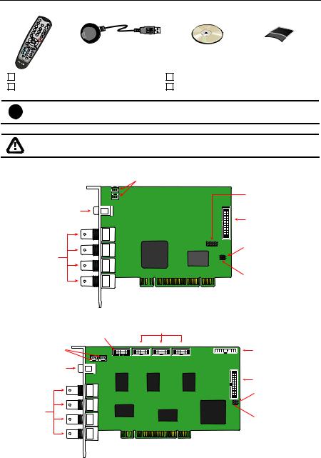
NV3000 Card Parts
|
TV out link connector |
|
Audio pin |
TV out port |
I/O connector |
|
|
BNC |
Reset pin |
video in |
|
ports |
|
|
Watchdog pin |
NV5000 Card Parts |
|
|
Display card connector |
Video extension card connectors |
|
|
||
TV out link |
Audio connector |
|
connector |
||
|
||
TV out port |
|
|
|
I/O connector |
|
|
Reset pin |
|
BNC |
|
|
video in |
Watchdog pin |
|
ports |
3
NV3000/5000/6000(EXP)/7000H User Manual
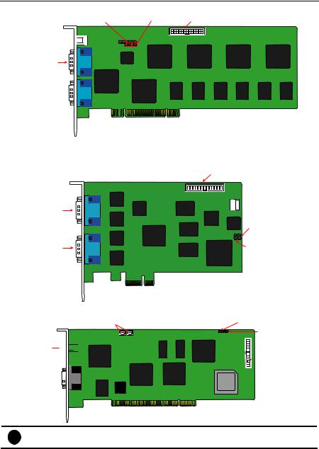
NV6000 Card Parts
Watchdog pin |
Reset pin I/O connector |
|
|
|
|
|
|
|
|
|
|
|
|
|
TV out port 


D-type AV IN
port 01
D-type AV IN
port 02 
NV 6000 Express Card Parts
|
I/O connector |
|
DVI AV IN |
|
|
port 01 |
|
|
|
Reset pin |
|
DVI AV IN |
Watchdog pin |
|
port 02 |
||
|
NV7000H Card Parts
TV out link connector |
Watchdog pin |
|
Reset pin |
TV out port 


 I/O connector
D-Type

AV IN port
i |
Brand new power supply with at least 350W and 20A support at 3.3V is |
recommended for installation of NV7000H |
4
Chapter 1 Introduction
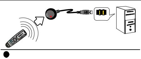
IR USB Receiver Part & Connection
 IR sensor
USB Port
i |
For detail of OSD kit installation, please refer to OSD kit Quick Guide. |
5

Chapter 2 Hardware Installation
2.1 Minimum System Requirements
First, must verify if the computer meets the minimum system requirements.
NV 3000/5000/6000/7000H:
|
|
|
|
|
NV3000 |
|
NV5000 |
|
|
NV6000 |
|
NV7000H |
|
|
|
CPU |
|
|
Pentium® 4 2.8GHz or above recommended |
|
|
||||||
|
|
Motherboard |
Intel 865, 875, 915, 925, 945, |
|
Intel 875, |
Intel 865, 875 |
|
||||||
|
|
|
|
955, NVIDIA nFORCE4 SLi - |
915, 925, |
|
Chipset |
|
|||||
|
|
|
|
Intel Edition Chipset |
945, 955, |
|
|
|
|||||
|
|
|
|
|
|
|
|
|
|
NVIDIA |
|
|
|
|
|
|
|
|
|
|
|
|
|
nFORCE4 |
|
|
|
|
|
|
|
|
|
|
|
|
|
SLi - Intel |
|
|
|
|
|
|
|
|
|
|
|
|
|
Edition |
|
|
|
|
|
|
|
|
|
|
|
|
|
chipset |
|
|
|
|
|
OS |
|
|
Windows2000 Professional or Windows XP Professional |
|
|||||||
|
|
|
|
|
NV7000H supports Windows XP Professional only. |
|
|||||||
|
|
|
|
|
|
|
|||||||
|
|
|
|
|
|
|
|
|
|
|
|
|
|
|
|
Expansion Slots |
|
1/2/3/4 × 32-bit PCI 2.1 compliant slots |
|
|
|||||||
|
|
RAM |
|
|
DDR 512MB or above |
|
|
|
|
|
|
||
|
|
Hard disk |
|
120GB of free hard disk space, or at least 60GB free space for |
|
||||||||
|
|
|
|
|
each partition |
|
|
|
|
|
|
|
|
|
|
Media |
|
|
CD-ROM drive |
|
|
|
|
|
|
|
|
|
|
VGA |
|
|
16-bit high color SVGA graphic card with DirectDraw & YUV |
|
|||||||
|
|
|
|
|
rendering capability, 64MB video memory |
|
|
||||||
|
|
Audio |
|
|
Sound card and speakers |
|
|
|
|
|
|
||
NV 6000 EXPRESS: |
|
|
|
|
|
|
|
|
|
|
|||
|
|
|
|
|
|
|
|
||||||
|
|
CPU |
|
|
Pentium® 4 2.8GHz or above recommended |
|
|
||||||
|
|
Motherboard |
|
Intel 875, 915, 925, 945, 955, NVIDIA nFORCE4 SLi - Intel |
|
||||||||
|
|
|
|
|
Edition chipset |
|
|
|
|
|
|
|
|
|
|
OS |
|
|
Windows2000 Professional or Windows XP Professional |
|
|||||||
|
|
|
|
|
|
|
|
|
|
|
|
|
|
|
|
Expansion Slots |
|
PCI-Ex1 Slot |
|
|
|
|
|
|
|
||
|
|
RAM |
|
|
DDR 512MB or above |
|
|
|
|
|
|
||
|
|
Hard disk |
|
120GB of free hard disk space, or at least 60GB free space for |
|
||||||||
|
|
|
|
|
each partition |
|
|
|
|
|
|
|
|
|
|
Media |
|
|
CD-ROM drive |
|
|
|
|
|
|
|
|
|
|
VGA |
|
|
16-bit high color SVGA graphic card with DirectDraw & YUV |
|
|||||||
|
|
|
|
|
rendering capability, 64MB video memory |
|
|
||||||
|
|
Audio |
|
|
Sound card and speakers |
|
|
|
|
|
|
||
|
|
i |
For AVerMedia® Security Product Hardware Recommendation list update, |
|
|||||||||
|
|
go to http://www.avermedia.com/nvd/hardware-recom.asp. |
|
|
|||||||||
6

Chapter 2 Hardware Installation
2.2 NV3000/5000/6000(EXP)/7000H Hardware Combinations
AVerMedia NV DVR provides powerful surveillance functions and flexible hardware combinations. The table shows the numbers of camera inputs, audio inputs, sensor inputs and relay outputs on different hardware combinations.
Before installing the cards, the computer must be turned OFF, the power cable must be UNPLUGGED and all other cables that are attached at the back of the computer must be DISCONNECTED.
When installing multiple cards, it is important to arrange the cards in sequence so that the cables would not tangle up.
NV3000 hardware combinations:
|
Hardware Combinations |
|
Camera Input |
|
Audio |
|
Sensor Input |
|
Relay Output |
|||||||||
|
|
|
|
|
|
|
|
|
|
|
|
Input |
|
|
||||
|
NV3000 Card |
|
|
I/O Audio Card |
|
|
|
|
|
|
|
|
|
|||||
|
|
|
|
|
|
|
|
|
|
|
|
|
||||||
|
|
1 |
|
|
|
|
|
0 |
|
|
4 |
|
0 |
0 |
0 |
|||
|
|
|
|
|
|
|
1 |
|
|
4 |
|
1 |
4 |
3 |
||||
|
|
|
|
|
|
|
|
|
|
|
||||||||
|
|
|
|
|
|
|
|
0 |
|
|
8 |
|
0 |
0 |
0 |
|||
|
|
2 |
|
|
|
|
|
1 |
|
|
8 |
|
1 |
4 |
3 |
|||
|
|
|
|
|
|
|
|
2 |
|
|
8 |
|
2 |
8 |
6 |
|||
|
|
|
|
|
|
|
|
0 |
|
|
12 |
|
0 |
0 |
0 |
|||
|
|
3 |
|
|
|
|
|
1 |
|
|
12 |
|
1 |
4 |
3 |
|||
|
|
|
|
|
|
|
|
2 |
|
|
12 |
|
2 |
8 |
6 |
|||
|
|
|
|
|
|
|
|
0 |
|
|
16 |
|
0 |
0 |
0 |
|||
|
|
4 |
|
|
|
|
|
1 |
|
|
16 |
|
1 |
4 |
3 |
|||
|
|
|
|
|
|
|
|
2 |
|
|
16 |
|
2 |
8 |
6 |
|||
NV5000 hardware combinations: |
|
|
|
|
|
|
|
|
||||||||||
|
|
|
|
|
|
|
|
|
|
|
|
|
|
|||||
|
|
Hardware Combinations |
|
|
|
Audio |
|
|
|
|
||||||||
|
|
|
|
|
|
|
|
|
|
|
|
Camera Input |
|
Sensor Input |
|
Relay Output |
||
|
NV5000 |
|
BNC Video |
I/O Audio |
|
Input |
|
|
||||||||||
|
|
|
|
|
|
|
|
|
||||||||||
|
Card |
|
Extension Card |
Card |
|
|
|
|
|
|
|
|
||||||
|
|
|
|
0 |
|
|
0 |
|
|
|
4 |
|
0 |
|
0 |
|
0 |
|
|
|
|
|
|
|
|
|
|
|
|
|
|
|
|
|
|
||
|
|
|
|
|
|
1 |
|
|
|
4 |
|
4 |
|
4 |
|
3 |
||
|
|
|
|
|
|
|
|
|
|
|
|
|
|
|||||
|
|
|
|
|
|
|
|
|
|
|
|
|
|
|
|
|
|
|
|
|
|
|
1 |
|
|
0 |
|
|
|
8 |
|
0 |
|
0 |
|
0 |
|
|
|
|
|
|
|
|
|
|
|
|
|
|
|
|
|
|
||
1 |
|
|
|
|
1 |
|
|
|
8 |
|
4 |
|
4 |
|
3 |
|||
|
|
|
|
|
|
|
|
|
|
|
|
|||||||
|
|
|
|
|
|
|
|
|
|
|
|
|
|
|
|
|
||
|
|
2 |
|
|
0 |
|
|
|
12 |
|
0 |
|
0 |
|
0 |
|||
|
|
|
|
|
|
|
|
|
|
|
|
|||||||
|
|
|
|
|
|
|
|
|
|
|
|
|
|
|
|
|
||
|
|
|
|
|
|
1 |
|
|
|
12 |
|
4 |
|
4 |
|
3 |
||
|
|
|
|
|
|
|
|
|
|
|
|
|
|
|||||
|
|
|
|
|
|
|
|
|
|
|
|
|
|
|
|
|
|
|
|
|
|
|
3 |
|
|
0 |
|
|
|
16 |
|
0 |
|
0 |
|
0 |
|
|
|
|
|
|
|
|
|
|
|
|
|
|
|
|
|
|
||
|
|
|
|
|
|
1 |
|
|
|
16 |
|
4 |
|
4 |
|
3 |
||
|
|
|
|
|
|
|
|
|
|
|
|
|
|
|||||
|
|
|
|
|
|
|
|
|
|
|
|
|
|
|
|
|
|
|
|
|
|
|
0 |
|
|
0 |
|
|
|
8 |
|
0 |
|
0 |
|
0 |
|
|
|
|
|
|
|
|
|
|
|
|
|
|
|
|
|
|
||
2 |
|
|
|
|
1 |
|
|
|
8 |
|
4 |
|
4 |
|
3 |
|||
|
|
|
|
|
|
|
|
|
|
|
|
|||||||
|
|
|
|
|
|
|
|
|
|
|
|
|
|
|
|
|
||
|
|
2 |
|
|
0 |
|
|
|
16 |
|
0 |
|
0 |
|
0 |
|||
|
|
|
|
|
|
|
|
|
|
|
|
|||||||
|
|
|
|
|
|
|
|
|
|
|
|
|
|
|
|
|
||
|
|
|
|
|
|
1 |
|
|
|
16 |
|
4 |
|
4 |
|
3 |
||
|
|
|
|
|
|
|
|
|
|
|
|
|
|
|||||
|
|
|
|
|
|
|
|
|
|
|
|
|||||||
NV6000 hardware combinations: |
|
|
|
|
|
|
|
|
||||||||||
|
|
|
|
|
|
|
|
|
|
|
|
|||||||
|
|
Hardware Combinations |
|
Camera Input |
Audio |
|
Sensor Input |
|
Relay Output |
|||||||||
|
|
|
|
|
|
|
|
|
|
|
|
|
|
|||||
|
NV6000 Card |
|
|
|
|
IO Card |
|
Input |
|
|
||||||||
|
|
|
|
|
|
|
|
|
|
|
|
|||||||
|
|
|
|
|
|
|
|
|
|
|
|
|
||||||
|
|
1 |
|
|
|
|
1 |
|
|
|
16 |
|
8 |
|
4 |
|
4 |
|
|
|
|
|
|
|
|
|
|
|
|
|
|
|
|
|
|
|
|
7

NV3000/5000/6000(EXP)/7000H User Manual
NV6000 Express hardware combinations:
Hardware Combinations |
|
Camera |
Audio |
Sensor Input |
Relay |
||||||
|
|
|
|
|
|
||||||
NV6480 Card |
|
IO Card |
|
Input |
Input |
Output |
|||||
|
|
|
|||||||||
|
|
|
|
|
|
|
|
||||
1 |
|
1 |
|
|
16 |
|
16 |
|
4 |
4 |
|
|
|
|
|
|
|
|
|
|
|
|
|
|
|
|
|
|
|
|
|
|
|
|
|
Hardware Combinations |
|
Camera |
Audio |
|
Relay |
||||||
|
|
|
|
|
|
Sensor Input |
|||||
NV6240 Card |
|
IO Card |
|
||||||||
|
|
Input |
Input |
Output |
|||||||
(8Channels) |
|
|
|
|
|
|
|
|
|
|
|
1 |
|
1 |
|
|
8 |
|
8 |
|
4 |
4 |
|
|
|
|
|
|
|
|
|
|
|
|
|
|
|
|
|
|
|
|
|
|
|
|
|
Hardware Combinations |
|
|
|
Audio |
|
|
|
||||
|
|
|
|
|
Camera Input |
|
|
Sensor Input |
Relay Output |
||
NV6240 Card |
|
|
IO Card |
|
|
||||||
|
|
|
|
Input |
|
||||||
(16 Channels) |
|
|
|
|
|
|
|
|
|
|
|
1 |
|
1 |
|
16 |
|
16 |
|
4 |
4 |
||
|
|
|
|
|
|
|
|
|
|
|
|
NV7000H hardware combinations: |
|
|
|
|
|
|
|
||||
|
|
|
|
|
|
|
|
||||
Hardware Combinations |
Camera Input |
|
Audio |
|
Sensor Input |
Relay Output |
|||||
|
|
|
|
|
|
|
|||||
NV7000H Card |
|
|
IO Card |
|
Input |
|
|||||
|
|
|
|
|
|
|
|
||||
|
|
|
|
|
|
|
|
|
|||
1 |
|
1 |
|
8 |
|
8 |
|
4 |
4 |
||
|
|
|
|
|
|
|
|
|
|
||
2 |
|
2 |
|
16 |
|
16 |
|
8 |
8 |
||
|
|
|
|
|
|
|
|
|
|
|
|
8
Chapter 2 Hardware Installation
2.3 NV3000 Hardware Installation
2.3.1 Installing (1) NV3000 and (1) I/O Audio cards (optional)
i |
The I/O audio card is an optional item. The D-type I/O port receives and transmit |
signal from the I/O box where the sensor and relay device are connected to it, |
|
|
while the audio input port receives the signal from the mic. NV3000 card is |
|
compatible with I/O Audio card that supports one audio input only. |
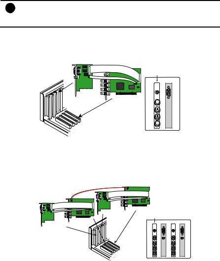
1.Remove the PC case cover.
2.Remove 2 brackets that cover the PCI slots. Save the screws.
3.Connect the NV3000 card and I/O Audio card with the connection cables.
4.Press the cards into the PCI slots firmly.
5.Secure the cards with the screws.
I/O Audio card
NV3000 card
NV3000 card
I/O Audio card
TV OUT
IN 1
AUDIO IN 1 1 

IN 2
Channel 2 IN 3
3
IN 4 4 
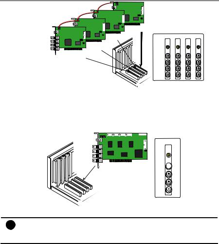
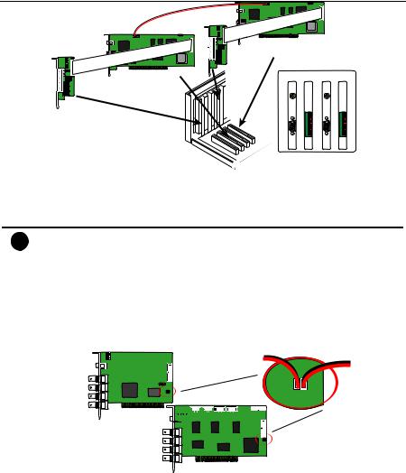
2.3.2 Installing (2) NV3000 and (2) I/O Audio cards (optional)
1.Remove the PC case cover.
2.Remove 4 brackets that cover the PCI slots. Save the screws.
3.Connect the NV3000 card and I/O Audio card with the connection cables.
4.Connect the (2) NV3000 cards with the supplied 20cm video signal line.
5.Press the cards into the PCI slots firmly.
6.Secure the cards with the screws.
20cm video signal line
NV3000 card 1
I/O Audio card 1
NV3000 card 2
I/O Audio card 2
NV3000 card 1 |
NV3000 card 2 |
I/O Audio card 1  I/O Audio card 2
TV OUT |
TV OUT |
IN 1 |
IN 1 |
AUDIO IN 1 |
AUDIO IN 1 |
1 |
5 |
IN 2 |
IN 2 |
Channel 3 2 |
7 6 |
IN 3 |
IN 3 |
IN 4 |
IN 4 |
4 |
8 |
2.3.3Installing (4) NV3000 cards
1.Remove the PC case cover.
2.Remove 4 brackets that cover the PCI slots. Save the screws.
3.Connect the (4) NV3000 cards with the supplied 20cm video signal line.
4.Press the cards into the PCI slots firmly.
5.Secure the cards with the screws.
9
NV3000/5000/6000(EXP)/7000H User Manual
20cm video signal line 20cm video signal line 
20cm video signal line
NV3000 card 1 |
|
|
|
|
|
|
NV3000 card 2 |
NV3000 |
Card 1 |
Card 2 |
Card 3 |
Card 4 |
|
|
||||||
NV3000 card 3 |
|
|
TV OUT |
TV OUT |
TV OUT |
TV OUT |
NV3000 card 4 |
|
|
IN 1 |
IN 1 |
IN 1 |
IN 1 |
|
|
1 |
5 |
|
9 |
13 |
|
Channel |
3 2 |
IN 2 |
IN 2 |
IN 2 |
IN 2 |
|
7 6 |
IN 3 |
11 10 |
15 14 |
||
|
|
|
IN 3 |
IN 3 |
IN 3 |
|
|
|
|
IN 4 |
IN 4 |
IN 4 |
IN 4 |
|
|
4 |
8 |
|
12 |
16 |
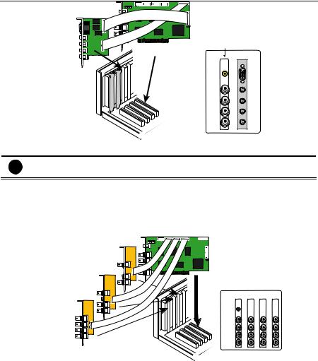
2.4 NV5000 Hardware Installation
2.4.1 Installing (1) NV5000 Card
1.Remove the PC case cover.
2.Remove a bracket that covers the PCI slot. Save the screw.
3.Press the NV5000 card into the PCI slot firmly.
4.Secure the card with the screws.
NV5000 card
NV5000 card
TV OUT
IN 1 1 
IN 2
Channel 2 IN 3
3
IN 4 4 
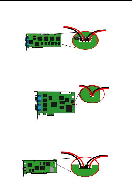
2.4.2Installing (1) NV5000 and (1) I/O Audio cards
i |
The I/O audio card is an optional item. The D-type I/O port receives and transmit |
signal from the I/O box where the sensor and relay device are connected to it, |
|
|
while the audio input port receives the signal from the mic. NV5000 card is |
|
compatible with the I/O Audio card that supports four (4) audio inputs. |
1.Remove the PC case cover.
2.Remove 2 brackets that cover the PCI slots. Save the screws.
3.Connect the NV5000 card and I/O Audio card with the connection cables.
4.Press the cards into the PCI slots firmly.
5.Secure the cards with the screws.
10
Chapter 2 Hardware Installation
I/O Audio card
NV5000 card
NV5000 card
I/O Audio card
TV OUT
|
IN 1 |
AUDIO IN 1 |
|
|
1 |
||
|
|
||
Channel |
IN 2 |
AUDIO IN 2 |
|
3 2 |
|||
|
|||
|
IN 3 |
AUDIO IN 3 |
|
|
|
||
|
IN 4 |
AUDIO IN 4 |
|
|
|
||
|
4 |
|
2.4.3Installing (1) NV5000 and (3) BNC video extension cards
i |
The BNC video extension card is an optional item. It comes with additional four (4) |
BNC video input ports that provide four (4) extra channels. |
1.Remove the PC case cover.
2.Remove 4 brackets that cover the PCI slots. Save the screws.
3.Connect the NV5000 card and BNC video extension cards with the connection cables.
4.Press the cards into the PCI slots firmly.
5.Secure the cards with the screws.
NV5000 card
BNC extension card 1
BNC extension card 2 


BNC extension card 3 


|
|
|
BNC video extension |
||
|
NV5000 |
Card 1 |
Card 2 |
Card 3 |
|
|
|
TV OUT |
|
|
|
|
|
IN 1 |
IN 1 |
IN 1 |
IN 1 |
|
1 |
5 |
|
9 |
13 |
Channel |
3 2 |
IN 2 |
IN 2 |
IN 2 |
IN 2 |
7 6 |
IN 3 |
11 10 |
15 14 |
||
|
|
IN 3 |
IN 3 |
IN 3 |
|
|
|
IN 4 |
IN 4 |
IN 4 |
IN 4 |
|
4 |
8 |
|
12 |
16 |
2.4.4Installing (1) NV5000, (1) I/O Audio (opt.) and (1) BNC video extension (opt.) cards
1.Remove the PC case cover.
2.Remove 3 brackets that cover the PCI slots. Save the screws.
3.Connect the NV5000 card, BNC video extension card and I/O Audio card with the connection cables.
4.Press the cards into the PCI slots firmly.
5.Secure the cards with the screws.
11
NV3000/5000/6000(EXP)/7000H User Manual
NV5000 card
BNC extension card 


I/O Audio card 


|
|
|
|
|
|
BNC video |
|
|
|
|
|
|
|
extension |
I/O Audio |
|
|
|
|
|
|
||
|
|
|
|
|
NV5000 |
card |
card |
|
|
|
|
|
|
|
|
TV OUT
|
IN 1 |
IN 1 |
|
1 |
5 |
Channel |
IN 2 |
IN 2 |
3 2 |
7 6 |
|
|
IN 3 |
IN 3 |
|
IN 4 |
IN 4 |
|
4 |
8 |
AUDIO IN 1
AUDIO IN 2
AUDIO IN 3
AUDIO IN 4
2.4.5Installing (2) NV5000, and (2) BNC video extension cards
1.Remove the PC case cover.
2.Remove 4 brackets that cover the PCI slots. Save the screws.
3.Connect the NV5000 card and BNC video extension card with the connection cables.
4.Connect the (2) NV5000 cards with the supplied 20cm video signal line.
5.Press the cards into the PCI slots firmly.
6.Secure the cards with the screws.
NV5000 card 1
BNC extension card 1 |
NV5000 card 2
BNC extension card 2 


NV5000 |
NV5000 |
BNC video |
BNC video |
extension |
extension |
||
card 1 |
card 2 |
card 1 |
card 2 |
TV OUT |
TV OUT |
|
|
IN 1 |
IN 1 |
IN 1 |
IN 1 |
1 |
5 |
9 |
13 |
IN 2 |
IN 2 |
IN 2 |
IN 2 |
Channel
2 |
6 |
|
10 |
14 |
|
IN 3 |
IN 3 |
IN 3 |
IN 3 |
3 |
7 |
|
11 |
15 |
|
IN 4 |
IN 4 |
IN 4 |
IN 4 |
4 |
8 |
|
12 |
16 |
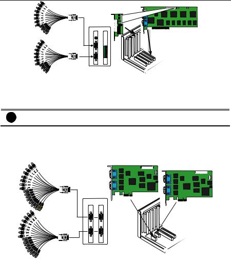
2.5 NV6000 Hardware Installation
The NV6000 can support up to 16 cameras and 8 audio input.
2.5.1Installing (1) NV6000 and I/O card
1.Remove the PC case cover.
2.Remove 2 brackets that cover the PCI slots. Save the screws.
3.Connect the NV6000 card and I/O card with the connection cable.
4.Press the cards into the PCI slot firmly.
5.Secure the card with the screws.
6.Connect the supplied AV connection cable to the D-type AV IN port.
12
Chapter 2 Hardware Installation
I/O card
|
NV6000 I/O card |
NV6000 card |
AV connection cable |
|
|
TV OUT |
|
AV connection cable
2.6 NV6000 Express Hardware Installation
The NV6000 Express can support up to 16 cameras and 8 audio inputs
2.6.1Installing (2) NV6000 Express
i |
The PC motherboard needs to have 2 PCI-Ex1 slots for installing 2 NV6000 |
Express card. |
1.Remove the PC case cover.
2.Remove 2 brackets that cover the PCI slots. Save the screws.
3.Press the cards into the PCI-Ex1 slot firmly.
4.Secure the card with the screws.
5.Connect the supplied AV connection cable to the DVI AV IN port.
AVconnection cable |
NV6000 Expresscard |
NV6000 Expresscard
NV6000 NV6000
Express Express
AVconnection cable |
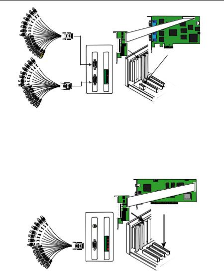
2.6.2Installing (1) NV6000 Express and I/O card
6.Remove the PC case cover.
7.Remove 2 brackets that cover the PCI slots. Save the screws.
8.Connect the NV6000 Express card and I/O card with the connection cable.
9.Press the cards into the PCI-Ex1 slots firmly.
10.Secure the card with the screws.
11.Connect the supplied AV connection cable to the DVI AV IN port.
13
NV3000/5000/6000(EXP)/7000H User Manual
AV connection cable
NV6000 Express card
I/O card
NV 6000
Express I/O card
AV connection cable
2.7 NV7000H Hardware Installation
The supplied AV connection cable provides up to 16 cameras and 8 audio inputs.
2.7.1Installing (1) NV7000H and I/O card
1.Remove the PC case cover.
2.Remove 2 brackets that cover the PCI slots. Save the screws.
3.Connect the NV7000H card and I/O card with the connection cable.
4.Press the cards into the PCI slot firmly.
5.Secure the card with the screws.
6.Connect the supplied AV connection cable to the D-type AV IN port.
AV connection cable
I/O card
NV7000H card
NV7000H I/O card
TV OUT
2.7.2 Installing (2) NV7000H and (2) I/O cards
1.Remove the PC case cover.
2.Remove 4 brackets that cover the PCI slots. Save the screws.
3.Connect the (2) NV7000H cards with the supplied 20cm video signal line.
4.Press the cards into the PCI slots firmly.
5.Secure the cards with the screws.
14
Chapter 2 Hardware Installation
I/O card 1
NV7000H card 1
I/O card 2
NV7000H card 2
NV7000H |
I/O |
NV7000H |
I/O |
card 1 |
card 1 |
card 2 |
card 2 |
TV OUT |
TV OUT |
2.8 Connecting the Watchdog line
The NV DVR program constantly monitors its operation. Connecting the NV3000/5000/6000/7000H to the motherboard reset switch panel, enables the unit to restart automatically and reset the system when an error has been detected.
i |
If more than one NV3000/5000/7000H card is installed, connect the watchdog line |
at last card. |
2.8.1 Connecting the Watchdog line to NV3000/5000
1.Look for the labeled RESET SW switch lead and connect it to the NV3000/5000 card reset pin.
2.Connect the supplied Watchdog line to the NV3000/5000 card watchdog pin and the other end to the motherboard RESET SW panel. If you are not sure, please refer to the motherboard user manual.
3.You may now replace back the PC cover and connect all the cables.
Reset SW lead
Watchdog line
NV3000 


NV5000
15
NV3000/5000/6000(EXP)/7000H User Manual
2.8.2 Connecting the Watchdog line to NV6000
1.Look for the labeled RESET SW switch lead and connect it to the NV6000 card reset pin.
2.Connect the supplied Watchdog line to the NV6000 card watchdog pin and the other end to the motherboard RESET SW panel. If you are not sure, please refer to the motherboard user manual.
3.You may now replace back the PC cover and connect all the cables.
Reset SW lead
Watchdog line
NV6000
2.8.3 Connecting the Watchdog line to NV6000 Express
1.Look for the labeled RESET SW switch lead and connect it to the NV6000 Express card reset pin.
2.Connect the supplied Watchdog line to the NV6000 Express card watchdog pin and the other end to the motherboard RESET SW panel. If you are not sure, please refer to the motherboard user manual.
3.You may now replace back the PC cover and connect all the cables.
Reset SW lead
Watchdog line
NV6000 Express
2.8.4 Connecting the Watchdog line to NV7000H
1.Look for the labeled RESET SW switch lead and connect it to the NV7000H card reset pin.
2.Connect the supplied Watchdog line to the NV7000H card watchdog pin and the other end to the motherboard RESET SW panel. If you are not sure, please refer to the motherboard user manual.
3.You may now replace back the PC cover and connect all the cables.
Reset SW lead
Watchdog line
NV7000H
16
Chapter 2 Hardware Installation
2.9 Connecting the Cameras, a TV and Audio device
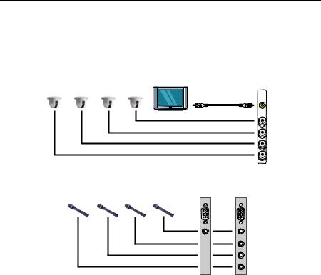
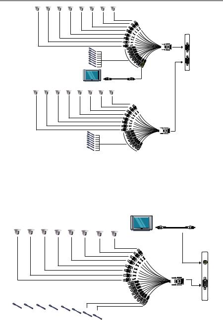
2.9.1 Connecting the Cameras, a TV and Audio device to NV3000/5000
1.Connect the cameras to the BNC video input port (see NV3000/5000 card parts). If you have installed more than one card, please refer the sequence of the camera to the number of cards installed in installing the card section.
2.Connect one end of the RCA video cable (not supplied) to the TV OUT port of NV3000/5000 card and the other end to the TV video input port. If you are not sure, please refer to the TV user manual.
NV3000/5000
Camera 1 Camera 2 Camera 3 Camera 4
TV OUT
Television |
RCA cable |
IN 1 |
|
|
IN 2 |
|
IN 3 |
|
IN 4 |
3.Connect the audio devices to the Audio input port of the I/O card.
|
|
|
NV3000 |
NV5000 |
|
|
|
I/O Audio |
I/O Audio |
|
|
|
card |
card |
MIC 4 |
MIC 3 |
MIC 2 |
MIC 1 |
|
|
|
|
AUDIO IN 1 |
AUDIO IN 1 |
|
|
|
|
AUDIO IN 2 |
|
|
|
|
AUDIO IN 3 |
|
|
|
|
AUDIO IN 4 |
2.9.2 Connecting the Cameras, a TV and Audio devices to NV6000
1.Use the supplied AV connection cable and connect it to the D-type AV IN port of NV6000 card (see NV6000 card parts).
2.Connect the cameras to the BNC video connectors and audio devices to the RCA audio connectors. Just follow the order basing on the marked sequence.
3.Connect one end of the RCA video cable (not supplied) to the TV OUT port of NV6000 card and the other end to the TV video input port. If you are not sure, please refer to the TV user manual.
17
NV3000/5000/6000(EXP)/7000H User Manual
Camera 1 Camera 2 Camera 3 Camera 4 Camera 5 Camera 6 Camera 7 Camera 8
Television |
RCA cable
NV6000
TV OUT
AV connection cable
MIC 1 |
|
MIC 2 |
MIC 3 |
MIC 4 |
|
|
|
|
||||||
Camera 9 |
Camera 10 Camera 11 Camera 12 Camera 13 Camera 14 Camera 15 Camera 16 |
|
|
|
|
|||||||||
|
|
|
|
|
|
|
|
|
|
|
|
|
|
|
|
|
|
|
|
|
|
|
|
|
|
|
|
|
|
|
|
|
|
|
|
|
|
|
|
|
|
|
|
|
|
|
|
|
|
|
|
|
|
|
|
|
|
|
|
|
|
|
|
|
|
|
|
|
|
|
|
|
|
|
|
|
|
|
|
|
|
|
|
|
|
|
|
|
|
|
|
|
|
|
|
|
|
|
|
|
|
|
|
|
|
|
|
|
|
|
|
|
|
|
|
|
|
|
|
|
|
|
|
|
|
|
|
|
|
|
|
|
|
|
|
|
|
|
|
|
|
|
|
|
|
|
|
|
|
AV connection cable
MIC 5 |
MIC 6 |
MIC 7 |
MIC 8 |
2.9.3 Connecting the Cameras, a TV and Audio devices to NV6000 Express
1.Use the supplied AV connection cable and connect it to the D-type AV IN port of NV6000 Express card (see NV6000 Expresscard parts).
2.Connect the cameras to the BNC video connectors and audio devices to the RCA audio connectors. Just follow the order basing on the marked sequence.
3.Connect one end of the RCA video cable (not supplied) to the TV OUT port of NV6000 Express card and the other end to the TV video input port. If you are not sure, please refer to the TV user manual.
18
Chapter 2 Hardware Installation
Camera 1 Camera 2 Camera 3 Camera 4 Camera 5 Camera 6 Camera 7 Camera 8
AV connection cable
NV6000 Express
MIC 1
MIC 2
MIC 3
MIC 4
MIC 5
MIC 6
MIC 7
MIC 8
RCA cable
Television
Camera 1 Camera 2 Camera 3 Camera 4 Camera 5 Camera 6 Camera 7 Camera 8
MIC 1
MIC 2
MIC 3
MIC 4
MIC 5
MIC 6
MIC 7
MIC 8
AV connection cable
2.9.4 Connecting the Cameras, a TV and Audio devices to NV7000H
1.Use the supplied AV connection cable and connect it to the D-type AV IN port of NV7000H card (see NV7000H card parts).
2.Connect the cameras to the BNC video connectors and audio devices to the RCA audio connectors. Just follow the order basing on the marked sequence.
3.Connect one end of the RCA video cable (not supplied) to the TV OUT port of NV7000H card and the other end to the TV video input port. If you are not sure, please refer to the TV user manual.
Camera 1 Camera 2 Camera 3 Camera 4 Camera 5 Camera 6 Camera 7 Camera 8 |
RCA cable |
|
|
|
Television |
NV7000H
TV OUT
|
|
|
|
|
|
|
|
|
|
|
|
|
|
|
|
|
|
|
|
|
|
|
|
|
|
|
|
|
|
|
|
|
|
|
|
|
|
|
|
|
|
|
|
|
|
|
|
|
|
|
|
|
|
|
|
MIC 1 MIC 2 |
MIC 3 |
MIC 4 |
|
|
|
|
|
|
|
||||
MIC5 |
|
|
|
|
|
||||||||
|
|
|
|
|
|
|
|
||||||
MIC6
MIC7
MIC8
AV connection cable
19
NV3000/5000/6000(EXP)/7000H User Manual
2.10 Dual Monitors Setup
The NV DVR system Supports Single and Dual monitor displays. When using dual monitors, the E-map and Playback function will be display on the second monitor.
The Video configuration is different for each different VGA chipsets. Please follow the steps below to setup the dual monitors display.
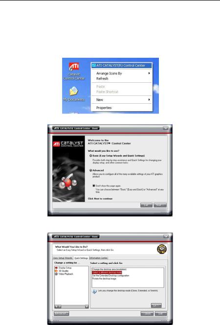
2.10.1Graphic card with ATi chipset
1.Enter the ATI Catalyst Control Center, user can click the short-cut or right click on the screen.
2. There are two modes to select ─ Basic and Advanced.
3.If user selected Basic mode, press the Quick Settings tab. Then select the Select a different desktop mode and click Go.
20

Chapter 2 Hardware Installation
4. Select the Extended Desktop and then click Finish.
5.If user selected the Advanced mode, click the View button.
6.In Display Manager, right click on the second Display on the right side and select Extend Main onto monitor.
7. Adjust each monitor resolution to 1024x768.
21
 Loading...