


AVerMedia®
AVerDiGi
EB3004 MD
User Manual
June 2009

FCC NOTICE (Class A)
This device complies with Part 15 of the FCC Rules. Operation is subject to the following two conditions: (1) this device may not cause harmful interference, and (2) this device must accept any interference received, including interference that may cause undesired operation.
.Federal Communications Commission Statement
NOTEThis equipment has been tested and found to comply with the limits for a Class A digital device, pursuant to Part 15 of the FCC Rules. These limits are designed to provide reasonable protection against harmful interference in a residential installation. This equipment generates uses and can radiate radio frequency energy and, if not installed and used in accordance with the instructions, may cause harmful interference to radio communications. However, there is no guarantee that interference will not occur in a particular installation. If this equipment does cause harmful interference to radio or television reception, which can be determined by tuning the equipment off and on, the user is encouraged to try to correct the interference by one or more of the following measures:
Reorient or relocate the receiving antenna.
Increase the separation between the equipment and receiver.
Connect the equipment into an outlet on a circuit different from that to which the receiver is connected.
Consult the dealer or an experienced radio/television technician for help.
Class A ITE
Class A ITE is a category of all other ITE which satisfies the class A ITE limits but not the class B ITE limits. Such equipment should not be restricted in its sale but the following warning shall be included in the instructions for use: Warning --This is a class A product. In a domestic environment this product may cause radio interference in which case the user may be required to take adequate measures.
European Community Compliance Statement (Class A)
This product is herewith confirmed to comply with the requirements set out in the Council Directives on the Approximation of the laws of the Member States relating to Electromagnetic Compatibility Directive 2004/108/EEC.
Warning - This is a Class A product. In a domestic environment this product may cause radio interference in which case the user may be required to take adequate measures to correct this interference.
DISCLAIMER
No warranty or representation, either expressed or implied, is made with respect to the contents of this documentation, its quality, performance, merchantability, or fitness for a particular purpose. Information presented in this documentation has been carefully checked for reliability; however, no responsibility is assumed for inaccuracies. The information contained in this documentation is subject to change without notice.
In no event will AVerMedia be liable for direct, indirect, special, incidental, or consequential damages arising out of the use or inability to use this product or documentation, even if advised of the possibility of such damages.
TRADEMARKS
"AVerMedia" is a trademark (or registered trademark) of AVerMedia Technologies, Inc and has been authorized AVerMedia Information Inc to use. Other trademarks used herein for description purpose only belong to each of their companies.
COPYRIGHT
©2009 by AVerMedia Information, Inc. All right reserved.
No part of this document may be reproduced or transmitted in any form, or by any means without the prior written permission of AVerMedia Information Inc. AVerMedia Information Inc. reserves the right to modify its models, including their characteristics, specifications, accessories and any other information stated herein without notice. The official printout of any information shall prevail should there be any discrepancy between the information contained herein and the information contained in that printout.
The mark of Crossed-out wheeled bin indicates that this product must not be disposed of with your other household waste. Instead, you need to dispose of the waste equipment by handing it over to a designated collection point for the recycling of waste electrical and electronic equipment. For more information about where to drop off your waste equipment for recycling, please contact your household waste disposal service or the shop where you purchased the product.
Battery Safety Information
-Store the batteries in a cool dry place.
-Do not dispose of used batteries in domestic waste. Dispose of batteries at special collection points or return to point of sale if applies.
-Remove the batteries during long periods of non-use. Always remove exhausted batteries from the remote control. Battery leakage and corrosion can damage this remote control, dispose of batteries safely.
-Do not mix old and new batteries.
-Do not mix different types of batteries: alkaline, standard (carbon-zinc) or rechargeable (nickel-cadmium).
-Do not dispose of batteries in a fire. The batteries may explode or leak.
-Never short circuit the battery terminals.
WARNING
TO REDUCE RISK OF FIRE OR ELECTRIC SHOCK, DO NOT EXPOSE THIS APPLIANCE TO RAIN OR MOISTURE
CAUTION
IF THERE IS ANY DAMAGE, SHORTAGE OR INAPPROPRIATE ITEM IN THE PACKAGE, PLEASE CONTACT WITH YOUR LOCAL DEALER. WARRANTY VOID FOR ANY UNAUTHORIZED PRODUCT MODIFICATION
NOTICE
-INFORMATION IN THIS DOCUMENT IS SUBJECT TO CHANGE WITHOUT NOTICE.
-THE INFORMATION CONTAINED HEREIN IS TO BE CONSIDERED FOR REFERENCT ONLY.
LIGHTNING WARNING
−TO AVOID THE LIGHTNING STRIKE, STRONGLY SUGGEST INSTALLING THE LIGHTNING ROD AT LIGHTNING FREQUENTLY AREA.
−FOR ADDED PROTECTION, UNPLUG THE DVR UNIT DURING THE LIGHTNING STORM. THIS MAY PREVENT TO DAMAGE THE DVR UNIT DUE TO THE LIGHTNING.

Table of Contents
Chapter 1 Introduction................................................................................ |
1 |
||
1.1 |
Package Content.................................................................................................. |
1 |
|
1.2 |
Features and Specifications ................................................................................. |
1 |
|
1.3 |
Front Panel........................................................................................................... |
2 |
|
1.4 |
Back Panel ........................................................................................................... |
2 |
|
1.5 |
Setting Up the DVR Unit....................................................................................... |
3 |
|
1.5.1 Installing the Hard Disk .................................................................................... |
3 |
||
1.5.2 |
Connecting Devices ......................................................................................... |
5 |
|
1.5.3 Connecting the Audio, Sensor and Relay device ............................................. |
6 |
||
Chapter 2 Operating the DVR unit ............................................................. |
8 |
||
2.1 |
Familiarizing the Remote Control Buttons ............................................................ |
8 |
|
2.1.1 |
Using AB Repeat Function............................................................................. |
10 |
|
2.1.2 |
Controlling PTZ Camera ................................................................................. |
11 |
|
|
2.1.2.1 To Enter the PTZ Mode ............................................................................... |
11 |
|
|
2.1.2.2 To Set Preset Position ................................................................................ |
12 |
|
|
2.1.2.3 To Control PTZ Camera ............................................................................. |
12 |
|
2.2 |
Using the DVR for the First Time........................................................................ |
13 |
|
2.3 |
Surveillance Screen ........................................................................................... |
14 |
|
2.3.1 Setup the Time Stamp.................................................................................... |
16 |
||
2.4 |
Playback the Video............................................................................................. |
17 |
|
Chapter 3 OSD Navigation Tree ............................................................... |
19 |
||
3.1 |
Menu Function.................................................................................................... |
21 |
|
Chapter 4 Using the USB Playback Console.......................................... |
34 |
||
4.1 |
Recommended system requirements................................................................. |
34 |
|
4.2 |
Installing the USB Playback Console ................................................................. |
34 |
|
4.3 |
Running the USB Playback Console .................................................................. |
35 |
|
4.3.1 To Cut and Save the Portion of the Recorded Video...................................... |
37 |
||
4.3.2 Playback DVR Recorded File from Hard Disk................................................ |
38 |
||
4.3.3 |
Playback Backup File(*.dvr)........................................................................... |
39 |
|
Chapter 5 Backup Recorded Video File .................................................. |
40 |
||
5.1 |
Familiarizing with HDD Backup Application ........................................................ |
40 |
|
5.2 |
To Backup Recorded Video File ......................................................................... |
41 |
|
Chapter 6 ImageVerification..................................................................... |
43 |
||
6.1 |
To Run the ImageVerification.............................................................................. |
43 |
|
Chapter 7 iEnhance................................................................................... |
44 |
||
7.1 |
To Use iStable .................................................................................................... |
45 |
|
Chapter 1 Introduction
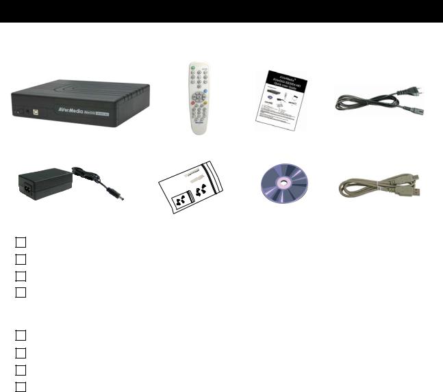
1.1Package Content
(4)
(1) |
(3) |
(2)
(5) |
(6) |
(7) |
(8) |
|
|||
|
|
|
(1) AVerDiGi EB3004 MD unit
(2) Remote Control (batteries included)
(3) Quick User Guide
(4) Power Cord
* The power cord varies depending on the standard power outlet of the country where it is sold.
(5) Power Adapter
(6) Internal HDD holder (8 screws are inculded)
(7) Software CD (User Manual included)
(8) USB Cable
1.2Features and Specifications
Fire resistance material
Non-PC stand-alone digital video recorder
4 composite video inputs and 1 composite output
VGA output for LCD or CRT monitor display
On Screen Display(OSD) control menu
MPEG4 video compression
Auto-detect NTSC or PAL video system
Supports 1 hard disk drive (not included)
Full-screen resolution:
Display: 720 x 480 (NTSC) / 720 x 576 (PAL)
Recording: 720 x 480 (NTSC) / 720 x 576 (PAL)
Recording frame rate:
D1 mode: 60fps (NTSC) / 50fps (PAL) CIF mode: 120 fps (NTSC) / 100fps (PAL)
D1 Enhance mode: 30fps (NTSC) / 25fps (PAL)
1
Scheduled recording (00:00~23:00 set by hour )
Search for recorded video files by date/time/event
Input/Output: 4 sensor inputs and 1 relay output control
Audio In/Out: 4 audio in and 1 audio out
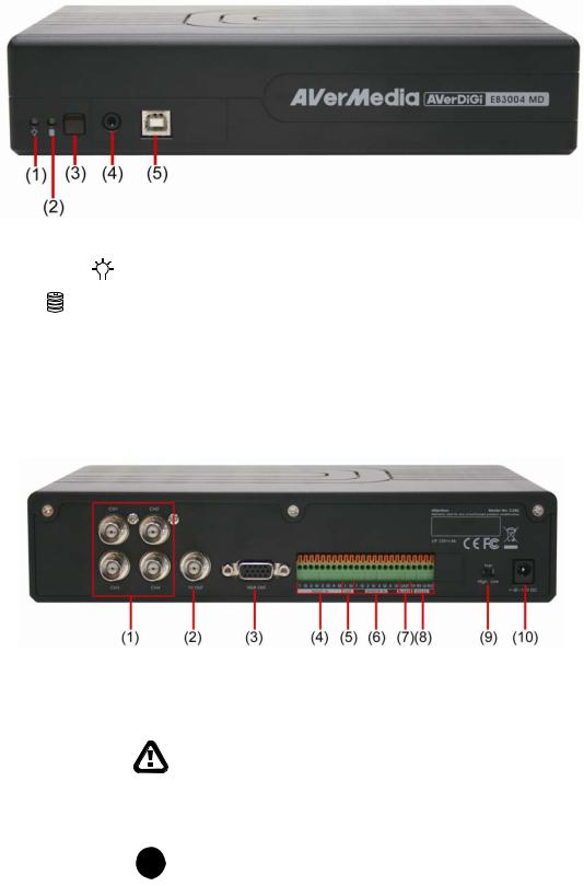
1.3Front Panel
|
Name |
|
Function |
|
|||
|
|
|
|
|
|
|
|
|
(1) DVR Power LED |
|
|
|
Light when the unit is power on |
||
|
|
|
|
|
|
||
|
|
|
|
|
|
|
|
|
(2) HDD LED |
|
Indicate the hard disk running state. Light when the HDD is running |
||||
|
|
(Read/Write) |
|||||
|
|
|
|
|
|
||
(3) |
IR Sensor |
Receive signal from the remote control to operate the unit |
|||||
|
|
|
|
||||
(4) |
IR Sensor Port |
To connect extended IR sensor cable(optional) |
|||||
|
|
|
|
||||
(5) |
USB 2.0 Port |
Connect to PC for video transfer or playback |
|||||
|
|
|
|
|
|
|
|
1.4Back Panel
Name |
Function |
|
|
|
|
|
|
(1) |
CH1/CH2/CH3/CH4 |
Input the video camera signal and display it on channel 1/2/3/4 |
|
|
|
|
|
(2) |
TV Out |
Output the video signal to other video output device through BNC port |
|
|
|
|
|
|
|
|
The DVR unit support 2 video output ports and you can only select |
|
|
|
to output the video either from the VGA OUT or VIDEO OUT |
|
|
|
|
(3) |
VGA OUT |
Output the video signal to a CRT or LCD monitor |
|
|
|
|
|
(4) |
Audio Out |
Input the audio signal from audio output device such as microphone |
|
|
|
|
|
|
|
i |
The audio input device has its own power supply is necessary. |
|
|
|
|
2
Name |
Function |
|
|
|
|
|
|
(5) |
Audio Out |
Output the audio signal to a audio out device such as speaker |
|
|
|
|
|
|
|
i |
The audio output device has its own power supply is necessary. |
|
|
|
|
|
|
|
|
(6) |
Sensor In |
Support 4 sensor devices |
|
|
|
|
|
(7) |
Alarm Out |
Support 1 relay device (Relay: 1A @ 125V AC/30V DC) |
|
|
|
|
|
(8) |
RS-232 |
For PTZ camera connection and firmware update |
|
|
|
|
|
(9) |
FAN speed Switch |
Adjust fan speed(High/Low) according to the actual environment situation |
|
|
We do strong recommend that adjust the fan speed to High when the |
|
operating environment is over 30 . |
|
|
|
|
(10)12V DC |
Power cable connection |
|
|
1.5Setting Up the DVR Unit
1.5.1 Installing the Hard Disk
i |
For hard disk spec, please referring to http://www.avermedia.com/AVerDiGi/Product/ → |
AverDiGi EB3004 MD → Hardware Recommendations |
The “compatible hard disks” indicated in the above recommendation list only means that these commercially available hard disks were tested with AVerMedia products and functioned well under normal operation conditions. AVerMedia does not guarantee or provide warranties, explicitly, implied or statutory with respect to the reliability of the hard disk function or its compatibility. In no event AVerMedia shall be liable for damages, with respect to any business interruption of clients, lost profits, loss of programs or other data on your information handling system or otherwise. This includes direct, indirect, incidental, special, or consequential damages, resulting from the incompatibility caused by the usage of these hard disks, even if AVerMedia has expressly advised about the risk of such damages. The entire risk arising out of the use of any information attached here with is borne by the recipient.
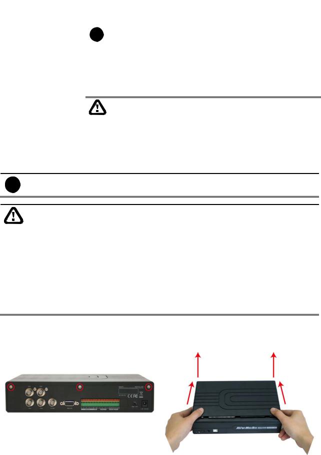
The DVR unit allows user to install one hard disk. Follow the illustrated instructions below to install the hard disk:
1. Loosen all screws |
2. Push the cover backward and lift |
3
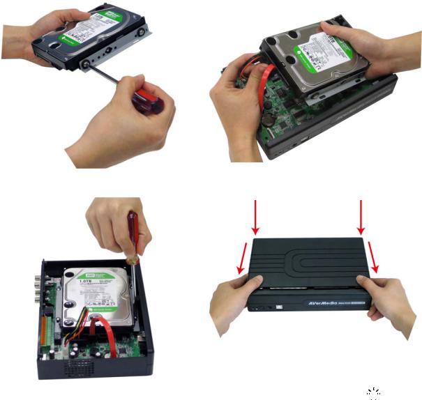
3.Secure the brackets on the hard disk
5.Secure the hard disk inside the unit then place unit cover
4.Connect the the SATA cable and the power connector to the hard disk
6.Push the cover forward and secure the cover
7. You may now connect all the cables. When the power is connected, the Power LED light 


 turns on
4
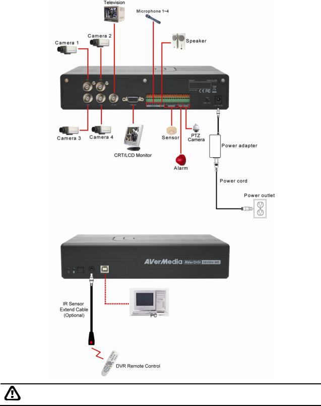
1.5.2 Connecting Devices
The back panel of the DVR unit, user can connect up to 4 video cameras, 4 sensor devices,
1 alarm device and output video to a TV or CRT/LCD monitor. Connecting the unit to the PC, then use the bundled software enables user to transfer, playback and segment the video. Follow the illustration below to make the connection:
Each time you change the video display output or video system (NTSC/PAL), the power must be turned off and on to reset the DVR unit.
5
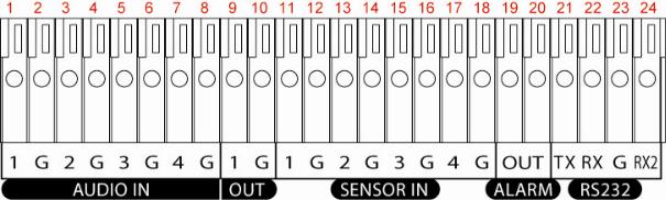
1.5.3 Connecting the Audio, Sensor and Relay device
The Sensor, Alarm, and audio port enable you to connect 4 sensor inputs, 1 relay outputs, and 4 audio in and 1 audio out device. Just connect the external sensor, relay, and audio in/out device pin directly to the pinhole. The RS-232 port can be used for PTZ camera connection through a RS-232 to RS-485 converter.
Check the table below and locate which pinhole is assigned to sensor input, relay output, and audio in/out.
The signal from the sensor (i.e., infrared sensors, smoke detectors, proximity sensors, door sensors, etc.) is being transmitted to the unit and this triggers the system to respond and send signal to relay device (i.e., alarm, telephone etc).
Audio in and out pinhole:
Pin # |
Definition |
1 |
Audio input signal |
2 |
Audio Ground signal |
3 |
Audio input signal |
4 |
Audio Ground signal |
5 |
Audio input signal |
6 |
Audio Ground signal |
7 |
Audio input signal |
8 |
Audio Ground signal |
9 |
Audio output signal |
10 |
Audio Ground signal |
6
Sensor in and Alarm pinhole:
|
Pin # |
Definition |
|
11 |
Sensor 1 signal |
|
12 |
Sensor 1 Ground signal |
|
13 |
Sensor 2 signal |
|
14 |
Sensor 2 Ground signal |
|
15 |
Sensor 3 signal |
|
16 |
Sensor 3 Ground signal |
|
17 |
Sensor 4 signal |
|
18 |
Sensor 4 Ground signal |
|
19 |
Relay signal |
|
20 |
Relay signal |
RS-232 pinhole: |
|
|
|
|
|
|
Pin # |
Definition |
|
21 |
RS-232 TX signal |
|
22 |
RS-232 RX signal |
|
23 |
RS-232 Ground signal |
|
24 |
RS-232 RX signal |
7

Chapter 2 Operating the DVR unit
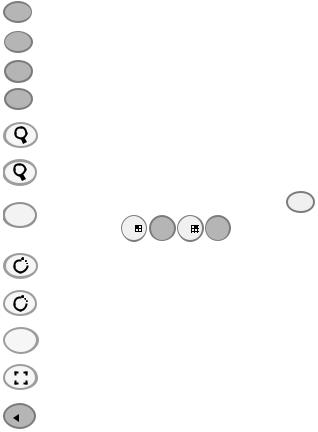
2.1Familiarizing the Remote Control Buttons
Use the Remote control to operate the OSD menu on surveillance screen.
Button
(8)
(9)
(10)
(11)
(12)
(13)
(14)
(15)
A-B
▲
▼▼ ▼▼
REC
Button |
|
Function |
||
(1) |
|
FN |
A functional key for multiple DVR system |
|
|
remote control |
|||
|
|
|
||
|
|
|
|
|
(2) |
|
1 |
Switch to Channel 1 |
|
|
As a number key for entering password |
|||
|
|
|
||
(3) |
|
3 |
Switch to Channel 2 |
|
|
As a number key for entering password |
|||
|
|
|
||
(4) |
|
7 |
Switch to Channel 3 |
|
|
As a number key for entering password |
|||
|
|
|
||
(5) |
|
9 |
Switch to Channel 4 |
|
|
|
|||
As a number key for entering password |
||||
|
|
|
||
|
|
|
|
|
(6) |
|
5 |
Switch to QUAD mode |
|
|
|
|||
As a number key for entering password |
||||
|
|
|
||
|
|
|
|
|
|
|
2 |
|
|
|
|
|
|
|
|
|
4 |
|
|
(7)6 As a number key for entering password
8
0
Function
Set a playing recorded video from A point to B point segment and repeat playing on surveillance screen(See 2.1.1)
Pause the playing
To play the video
Decrease the video playback at the speed of 2x, 4x, 8x or 16x
Fast play the video playback at the speed of 2x, 4x, 8x or 16x
Stop playing / Stop recording
Start video recording
To enter the OSD Main menu / Exit from the main menu or sub-menu display
8
Button |
|
|
|
|
|
|
|
|
Function |
|
|
|
|
|
|
▼ |
|
|
|
||||||
|
|
|
|
|
|
|
|
|
|
To move the selection to the left and right |
||
(16) |
|
▼ |
||||||||||
|
|
|
|
|||||||||
|
|
|
|
|
|
|
|
|
|
|
|
|
|
▲ |
To go up and down and select the items in the menu list or change the settings |
||||||||||
|
|
|||||||||||
|
|
|
|
|
|
|
|
|
|
|||
|
|
▼ |
||||||||||
|
|
|
|
|
||||||||
|
|
|
|
|
|
|
|
|
|
|
|
|
|
|
ZOOM+ |
|
|
|
|||||||
(17) |
|
|
|
|
|
|
|
|
|
To zoom in view of PTZ camera |
||
|
|
|
|
|
|
|
|
|
||||
|
|
|
|
|
|
|
|
|
|
|
|
|
|
ZOOM- |
|
|
|
||||||||
|
|
|
|
|
|
|
|
|
|
To zoom out view of PTZ camera |
||
|
|
|
|
|
|
|
|
|
|
|||
|
|
|
|
|
|
|
|
|
|
|
||
(18) |
|
PTZ |
PTZ camera control button. Press PTZ + camera channel |
|||||||||
|
button( 1 |
2 3 |
4 )can enter PTZ mode to control PTZ camera.(see 2.1.3) |
|||||||||
|
|
|
|
|
|
|
|
|
|
|||
|
|
|
|
|
|
|
|
|
|
|
|
|
|
|
SPEED+ |
|
|
|
|||||||
(19) |
|
|
|
|
|
|
|
|
|
To speed up movement of PTZ camera lens |
||
|
|
|
|
|
|
|
|
|
|
|
|
|
|
SPEED- |
|
|
|
||||||||
|
|
|
|
|
|
|
|
|
|
To speed down movement of PTZ camera lens |
||
|
|
|
|
|
|
|
|
|
|
|||
|
|
|
|
|
|
|
|
|||||
|
|
FOCUS + |
|
|
|
|||||||
(20) |
|
|
|
|
|
|
|
|
|
To focus in PTZ camera lens |
||
|
|
|
|
|
|
|
||||||
|
FOCUS - |
|
|
|
||||||||
|
|
|
|
|
|
|
|
|
|
To focus out PTZ camera lens |
||
|
|
|
|
|
|
|
|
|
|
|||
|
|
|
|
|
|
|
|
|
|
|
|
|
(21) |
|
|
|
|
|
|
|
|
|
Make a selection |
|
|
|
|
|
|
|
|
|
|
|
|
|||
|
|
|
|
|
|
|
|
|
Enter sub-menu |
|
||
|
|
|
|
|
|
|
|
|
|
|||
|
|
|
|
|
|
|
|
|
|
|
||
9
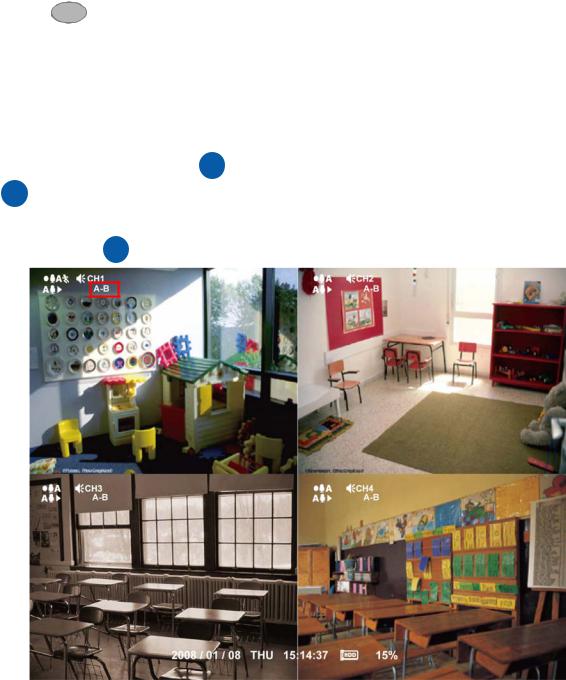
2.1.1 Using AB Repeat Function
AB Repeat function allow user to set a video segment from A to B point and play on the surveillance screen until user stop.
1.Press ▲ (play button) to call out the SEARCH MODE menu to find the recorded video that user wants to playback.
2.Select TIME SEARCH or EVENT LIST.
-TIME SEARCH (search by date and time): select the date and time from where you want to begin the video playback.
-EVENT LIST (search by condition): select from the list.
3. During the playback, press A-B to set the A point of video segment. And then, press A-B again to set the B point of video segment. On the surveillance screen will display “A-B” and repeat playing the AB point video segment which user has set. To cancel AB repeat, press A-B again.
10
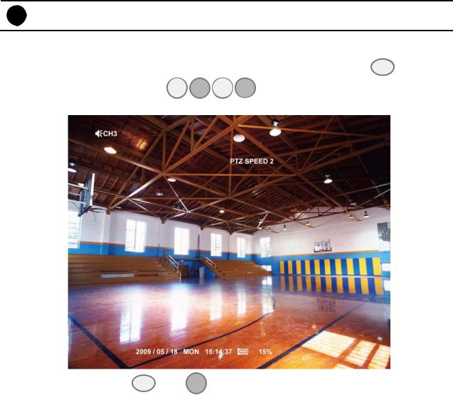
2.1.2 Controlling PTZ Camera
Using remote control, user can easily control PTZ camera at local site. Before starting, make sure the PTZ camera is connected with the DVR unit. And then, please go to OSD menu to enable PTZ control (see also 3.1 Menu Function: PTZ Setup).
i Use the RS-232 to RS-485 converter to connect the PTZ camera with the DVR unit.
2.1.2.1 To Enter the PTZ Mode
To control PTZ camera, user need to enter the PTZ mode first. Press PTZ button, and camera channel number button ( 1 

 2 3
2 3  4 ). The surveillance monitor will switch to single screen PTZ mode.
To exit PTZ mode, press PTZ and 0 button. Also, when the DVR system is idle over 1 minute, the DVR system will automatically exit PTZ mode.
11
 Loading...