

What’s in the Package
Vertical Stand
N
I
V
/
A
N
I
-
S
AVerMedia AVerTV Box7
E
N
O
H
P
R
A
E
User’s Manual
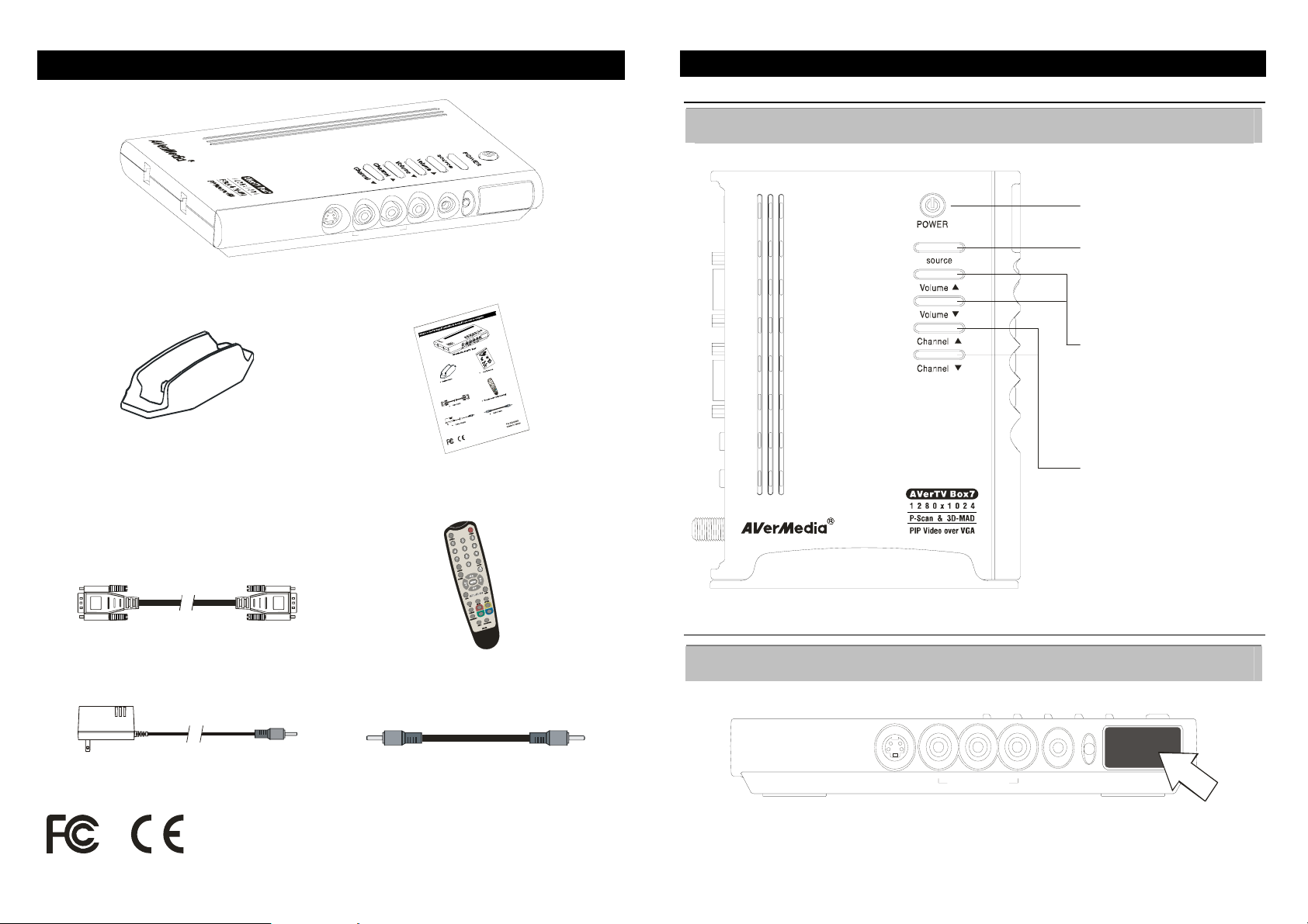
The AVerMedia AVerTV Box7 Unit
Touch Button Control Panel
The Touch Button Panel found on the top side of the AVerTV Box7 provides quick access to commonly
used functions.
POWER
Turn the unit on /off
SOURCE
Press this button to toggle between
TV/Video and PC display
VOLUME /ST
Press Volume to increase and
Volume to decr ease th e volum e
level
S
T
CHANNEL /ST
Press Channel to go up and
Channel to go down to the next
active TV channel
S
T
VGA Cable
Remote Control (with batteries)
Infrared Sensor
When using the remote control, aim it at the In-frared Sensor which is located at the front panel of the
AVerTV Box7.
Power Adapter
Audio Cable
S - IN
A / V IN
EAR PHONE
P/N 300AABWG
1
Made in Taiwan
2

Connection Ports
A
A
The port connectors allow connection of your TV antenna, PC, VGA monitor or LCD projector, speakers,
video, or s-video source etc.
VGA OUTPUT to
MONITOR
DC VGA OUT VGA IN AUD IO IN S PE AKE R OUT AN T IN
POWER
DAPTER
UDIO INPUT from PC’s
SOUND CARD
VGA INPUT
from PC
AVerMedia AVerTV Box7 Back Panel
TV ANTENNA
(75 )Ω
SPEAKER
CONNECTION
Left & Right AUDIO INPUT
COMPOSITE VIDEO INPUT
Ω
Ω
PAL
PC Sound Card
OUT
TV ANTENNA (75 )
NTSC
TV ANTENNA ( 75 )
External Amp lifi ed Speaker
N
I
T
N
A
T
U
O
R
Audio Cable(suppli ed)
E
K
A
E
P
S
N
I
O
I
D
U
A
N
I
A
G
V
T
U
O
A
G
V
S-VIDEO INPUT
S - IN
A / V IN
EAR PHONE
EARPHONE JACK
AVerMedia AVerTV Box7 Front Panel
The Installation and Setup section provides more information on cable connections.
3
VGA Cable (supplied)
C
D
(not supplied)
VGA Monitor
VGA Cable
IBM Compatible PC
POWER ADAPTER
Wal l Ou tl et
LCD PROJECTOR
Installation and Setup
The figure below shows the proper cable connections for installing AVerTV Box7 and connecting it to your audio/video equipment.
4
 Loading...