

AVerMedia VC520 Pro Service Manual
VC520 Pro
User Manual

Federal Communications Commission Statement
NOTE: This equipment has been tested and found to comply with the limits for a Class A
digital device, pursuant to part 15 of the FCC Rules. These limits are designed to
pro-vide reasonable protection against harmful interference when the equipment is
operate din a commercial environment. This equipment generates, uses, and can radiate
radiofrequency energy and, if not installed and used in accordance with the instruction manual, may
cause harmful interference to radio communications. Operation of this equipment in a residential area
is likely to cause harmful interference in which case the user will be required to correct the interference
at his own expense.
FCC Caution: Any changes or modifications not expressly approved by the party responsible for
compliance could void the user's authority to operate this equipment.
This device complies with part 15 of the FCC Rules.
Operation is subject to the following two conditions:
(1) This device may not cause harmful interference, and
(2) this device must accept any interference received, including interference that may cause undesired
operation.
Warning:
This is a class A product. In a domestic environment this product may cause radio interference in
which case the user may be required to take adequate measures.
DISCLAIMER
No warranty or representation, either expressed or implied, is made with respect to the contents of this
documentation, its quality, performance, merchantability, or fitness for a particular purpose. Information
presented in this documentation has been carefully checked for reliability; however, no responsibility is
assumed for inaccuracies. The information contained in this documentation is subject to change
without notice.
In no event will AVer Information Inc. be liable for direct, indirect, special, incidental, or consequential
damages arising out of the use or inability to use this product or documentation, even if advised of the
possibility of such damages.
TRADEMARKS
“AVer” is a trademark owned by AVer Information Inc. Other trademarks used herein for description
purpose only belong to each of their companies.
COPYRIGHT
©2020 AVer Information Inc. All rights reserved.
All rights of this object belong to AVer Information Inc. Reproduced or transmitted in any form or by any
means without the prior written permission of AVer Information Inc. is prohibited. All information or
specifications are subject to change without prior notice.

NOTICE
WARNING
nc) or
- Do not attempt to short-circuit the battery terminals.
Support.usa@aver.com
SPECIFICATIONS ARE SUBJECT TO CHANGE WITHOUT PRIOR NOTICE. THE
INFORMATION CONTAINED HEREIN IS TO BE CONSIDERED FOR REFERENCE ONLY.
THE CONTENTS ARE SUBJECT TO CHANGE WITHOUT PRIOR NOTICE. IF THE CONTENT
IS WRONG, PLEASE INFORM US TO MAKE CORRECTIONS.
To reduce risk of fire or electric shock, do not expose this appliance to rain or moisture.
Warranty will be void if any unauthorized modifications are done to the product.
Do not drop the camera or subject it to physical shock.
Use correct power supply voltage to avoid damaging camera.
Do not place the camera where the cord can be stepped on as this may result in fraying or
damage to the lead or the plug.
Hold the bottom of the camera with both hands to move the camera. Do not grab the lens or
lens holder to move the camera.
Remote Control Battery Safety Information
- Store batteries in a cool and dry place.
- Do not throw away used batteries in the trash. Properly dispose of used batteries through
specially approved disposal methods.
- Remove the batteries if they are not in use for long periods of time. Battery leakage and
corrosion can damage the remote control. Dispose of batteries safely and through approved
disposal methods.
- Do not use old batteries with new batteries.
- Do not mix and use different types of batteries: alkaline, standard (carbon-zi
rechargeable (nickel-cadmium).
- Do not dispose of batteries in a fire.
Contact Information
Global
AVer Information Inc.
www.aver.com
8F, No.157, Da-An Rd., Tucheng Dist.,
New Taipei City
Taiwan
Tel: +886-2-2269-8535
Fax: +886-2-2269-8537
USA
AVer Information Inc.
668 Mission Ct.
Fremont, CA 94539
www.averusa.com
Toll -free: 1(877)528-7824
Local: 1(408)263-3828
AVer Information Europe B.V.
Westblaak 140, 3012KM,
Rotterdam, Netherland
Tel: +31(0)10 7600 550
Technical support:
EU.RMA@aver.com

Contents
Package Contents ................................................................................................... 1
Optional Accessories .............................................................................................. 1
Product Introduction ................................................................................................ 2
Overview ................................................................................................................. 2
Expansion Speakerphone/Microphone Connection ................................................ 3
Phone in Connection ............................................................................................... 4
Pan and Tilt Angle ........................................................................................... 4
Audio Signal Receive Range .................................................................................. 5
Speakerphone LED Indicator .................................................................................. 6
Remote Control ....................................................................................................... 7
Installation ............................................................................................................... 9
Device Connection .................................................................................................. 9
RS232 Connection ................................................................................................ 11
Wall Mount Installation .......................................................................................... 17
Operating the Camera .......................................................................................... 20
Make a Video Call ................................................................................................. 20
Make a Connection by AVer IP Finder App ........................................................... 20

Use SmartFrame Function ............................................................................ 22
What is SmartFrame? ................................................................................... 22
Two kinds of SmartFrame Function .............................................................. 22
How does SmartFrame Work ........................................................................ 23
Login .............................................................................................................. 24
Live Screen Operation................................................................................... 25
Setup the Preset ............................................................................................ 25
Select the Preset Position ............................................................................. 27
Camera Settings ............................................................................................ 28
Smart Frame .......................................................................................... 28
Auto Focus ............................................................................................ 28
Home Position ....................................................................................... 29
Sleep Position ........................................................................................ 29
Sleep Timer ........................................................................................... 29
On Screen Menu ................................................................................... 30
Camera Binding ..................................................................................... 30
Image Settings .............................................................................................. 31
Image Flip .............................................................................................. 31
Image Mirror .......................................................................................... 31

True WDR .............................................................................................. 32
Frequency .............................................................................................. 32
White Balance ....................................................................................... 33
Noise Reduction .................................................................................... 33
Brightness .............................................................................................. 34
Sharpness.............................................................................................. 34
Saturation .............................................................................................. 35
RS232 Setting ............................................................................................... 35
Video Format Setting ..................................................................................... 36
IP Stream Resolution ............................................................................. 36
Frame Rate ............................................................................................ 36
Bit Rate .................................................................................................. 37
RTSP ..................................................................................................... 37
RTMP ..................................................................................................... 39
Network Setting ............................................................................................. 40
DHCP ..................................................................................................... 40
Static IP .................................................................................................. 40
System Setting .............................................................................................. 41
Language ............................................................................................... 41

FW Update............................................................................................. 42
Reset Settings ....................................................................................... 43
Camera Reboot ..................................................................................... 44
Change Password ................................................................................. 45
SSL Certificate ....................................................................................... 46
Date Format ........................................................................................... 47
Time Format .......................................................................................... 47
Time Correction Mode ........................................................................... 48
Information ............................................................................................. 48
Audio Setting ................................................................................................. 49
Noise Suppression ................................................................................ 49
Automatic Gain Control ......................................................................... 49
Echo Cancellation .................................................................................. 50
Keyboard Noise Suppression ................................................................ 50
Phone In Jack ........................................................................................ 51
Operating the AVer PTZApp .................................................................................. 52
Install AVer PTZApp .............................................................................................. 52
Use AVer PTZApp to Setup the Camera ............................................................... 52
Set the Camera Number ............................................................................... 60

Hotkey Control ............................................................................................... 62
Home / Sleep Position ................................................................................... 63
ADDR / Protocol / Baud Rate ........................................................................ 63
OpenGL ......................................................................................................... 64
Use AVer PTZApp to Setup the Speakerphone .................................................... 65
Use AVer EZLive ................................................................................................... 66
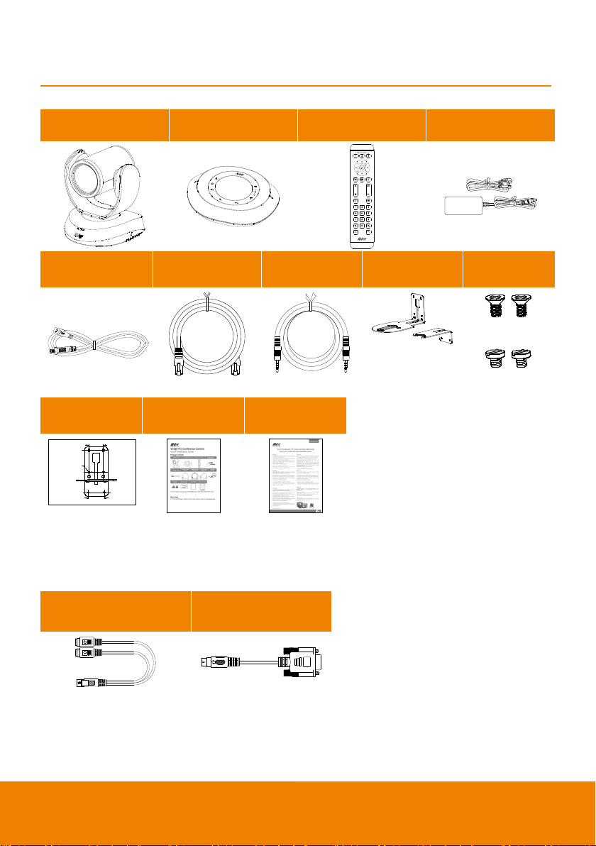
Package Contents
L=7.5mm(x2)
P/N: 303AU340-AGR
46.00[1.81]
51.00[2.01]
Ø5.50[Ø0.22]
Camera Unit Speakerphone Unit Remote Control
Power Adapter
Power Cord*
USB 3.0 Cable
Drilling Paper Quick Guide Warranty Card
Speakerphone
Cable (10m)
3.5 mm Audio
Cable (0.9m)
L-Mount
Bracket
Screws for
Mount
M4 x 8mm(x2)
1/4”-20
*The power cord will vary depending on the standard power outlet of the country where it is sold
Optional Accessories
RS232 Cable
(MINI DIN 9 to MINI DIN 8)
(MINI DIN 8 to D-Sub9)
RS232 Cable
1
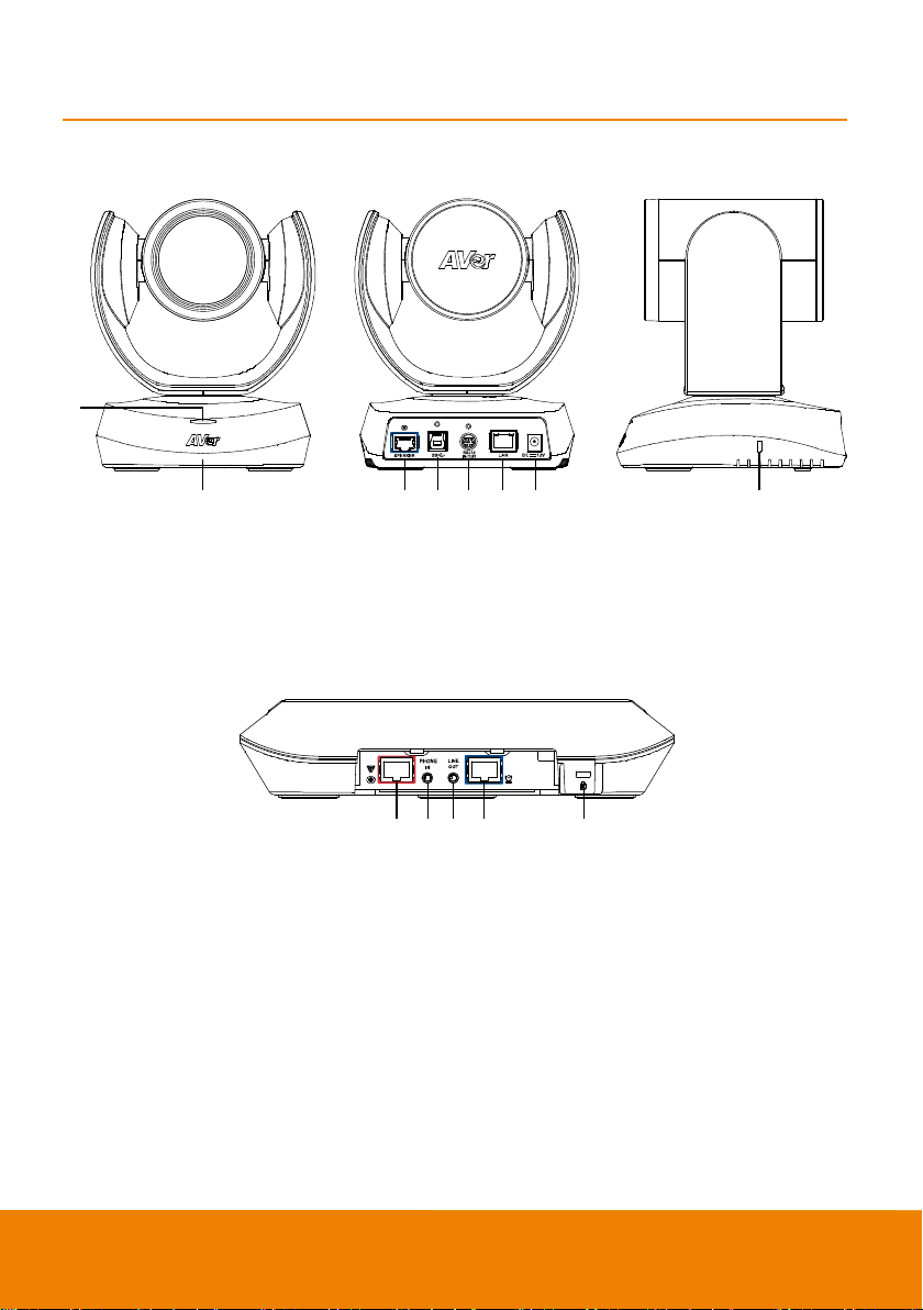
Product Introduction
1
2 3 4 5 6 7 8
2
IR sensor
7
DC 12V power jack
9 1011 12 13
Red cable)
13
Kensington Lock
Overview
1
Status LED
Power on: Red light
Standby: Orange light
3 Speakerphone port(Blue cable) 8 Kensington Lock
4
USB3.1 Type B port
5
RS232 in/out port
6
Ethernet port
9 Speakerphone port
(For extended speakerphone
and microphone connection/
10
Phone in port
11
Line out port
12
Camera port(Blue cable)
2
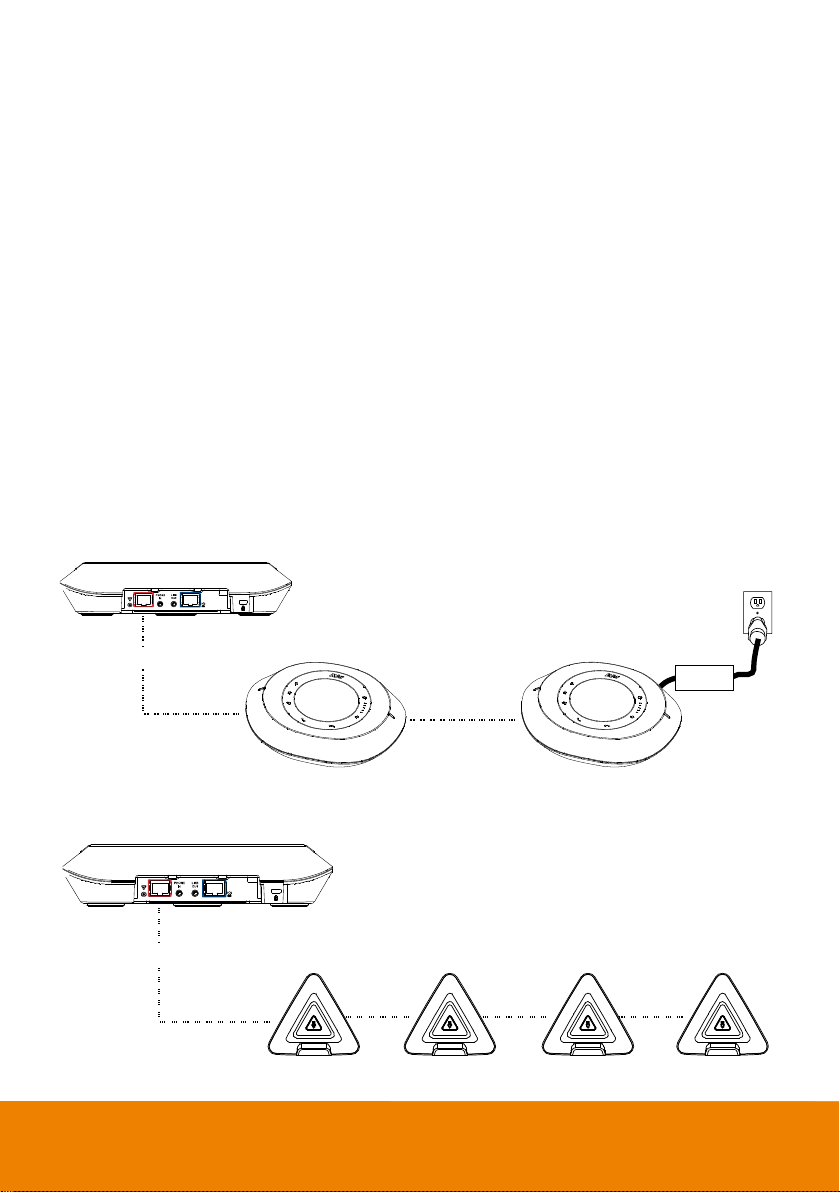
Expansion Speakerphone/Microphone
VC520 Pro speakerphone
Expansion speakerphone
Speakerphone cable
Expansion speakerphone
Power adapter
Microphone cable
Expansion
microphone
Expansion
microphone
Expansion
microphone
Expansion
microphone
VC520 Pro speakerphone
Connection
There are 2 types of expansion solutions that can be extended from the VC520 Pro speakerphone.
Please purchase the expansion speakerphone and/or microphone directly from AVer or an AVer
reseller.
Expansion Speakerphone Requirements:
- VC520 Pro Firmware version: 1004.00 or later
- FONE540 Firmware version: 7000.34 or later
[Note]
The VC520 Pro can support up to two expansion speakerphones, however, the daisy-chain
expansion cable cannot exceed over 40m in total.
Please connect the power supply for the expansion speakerphone when daisy-chaining over 20m.
Please connect the power supply when upgrading the firmware for the expansion speakerphone.
The expansion speakerphone cannot be used as the main speakerphone; it can only be used with
the VC520 Pro.
The speakerphone/microphone cables will be included in the package contents when the user
purchases the expansion speakerphone/microphone.
3
[Note] The VC520 Pro can support up to four expansion microphones, however, the daisy-chain
Mobile phone
3.5mm audio cable
expansion cable cannot exceed over 40m in total.
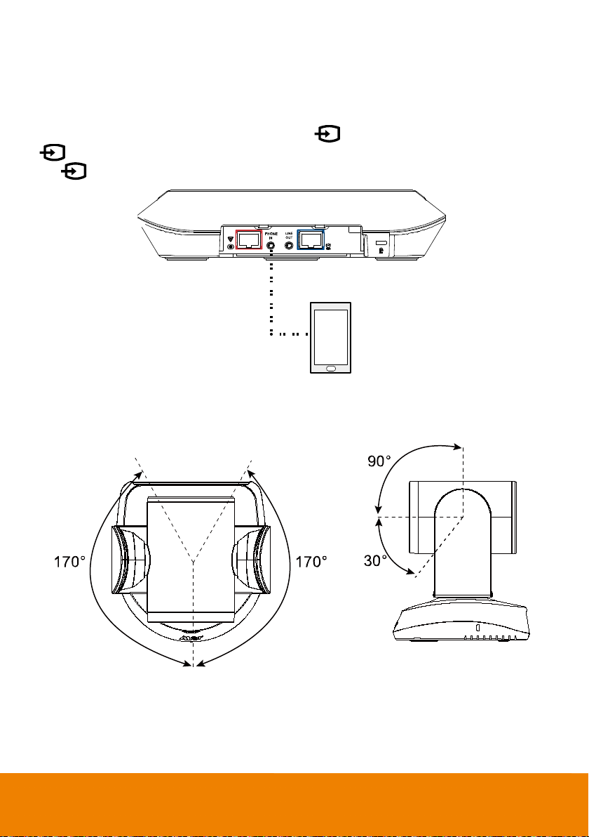
Phone in Connection
Users can connect a mobile phone to the Phone in port on the speakerphone as a hands-free speaker.
When the device connects with the speakerphone, the
icon will temporarily disconnect the connection of the device with the speakerphone; touching
the
icon again will resume the connection.
icon will light up in blue. Touching the
Pan and Tilt Angle
4
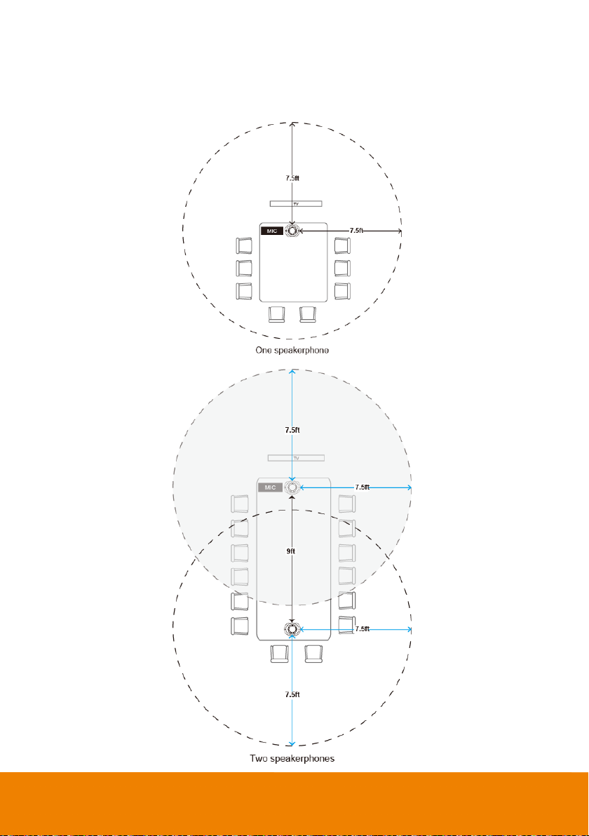
Audio Signal Receive Range
The best distance for the speakerphone to receive audio signal is within 7.5ft in radius. When
connecting two or more speakerphones, the distance between the speakerphones must be 9ft.
5
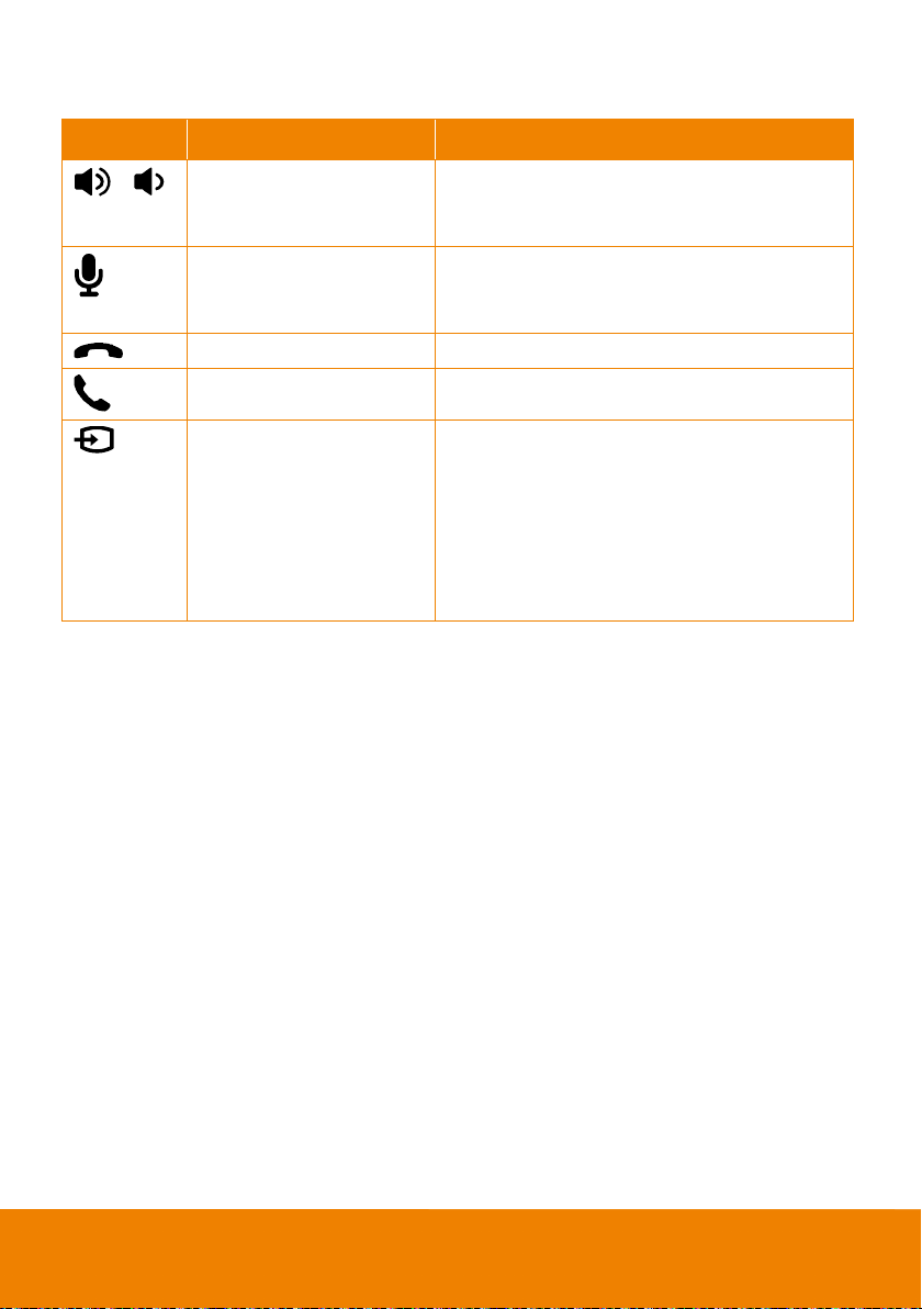
Speakerphone LED Indicator
will light up in blue.
mute the speakerphone volume.
red.
external devices
Button LED Indicator Statu s
/
White light
White/Blue light
Red light Touch to hang up the call.
Green light Touch to answer the incoming call.
Blue light: Connects with
external device
White light: Temporarily
disconnects the
connection with the device
Off: No connection with
Adjust the volume up and down. When adjusting
the volume up and down, the volume LED indicator
Touch to mute/un-
In mute status, the LED indicator will light up in
When the Phone in port connects with the device,
the LED indicator will light up in blue.
6
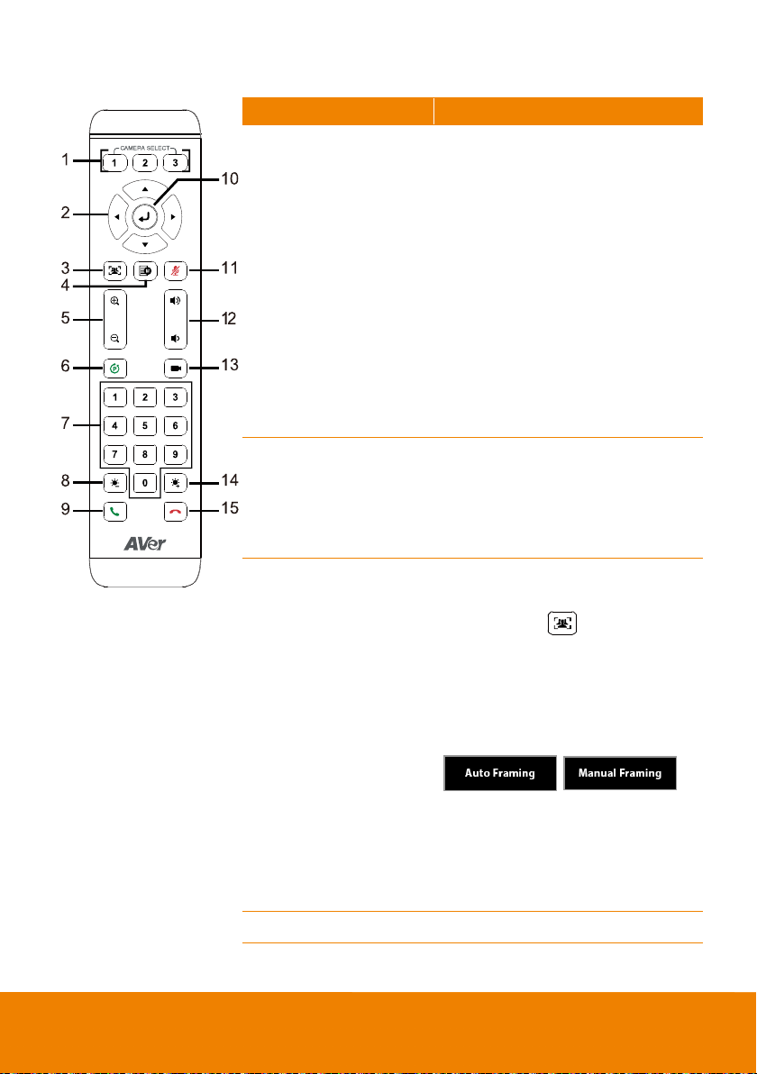
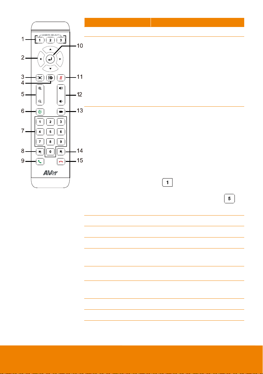
Remote Control
Name
Function
1. Camera Select
2. Camera Direction
Control
3. SmartFrame
4. OSD Menu
One remote can control up to 3 AVer
VC/CAM/VB series cameras. You can
use AVer PTZApp to set numbers
associated with each camera, and then
select which camera you would like to
control using the remote.
[Note] If you only have one camera
that requires no additional setting, the
default is camera 1.
If camera 2 or 3 is selected, the remote
will be unable to control the camera.
In this case, please press camera 1 on
your remote.
Use the directional buttons on the
remote to control the direction of the
camera. Press the directional button to
move the camera or press and hold to
continuously pan or tilt.
One-click automatic FOV adjustment
to fit all participants.
Press and hold
remote for 2 seconds to switch the
SmartFraming function between auto
and manual mode; a message (as
figure shown) will display on the screen
to indicate auto or manual mode.
[Note] While in the video conference
meeting, participants must face the
camera for proper face detection
(SmartFrame). Side facial profiles are
not detectable.
Not supported for VC520 Pro.
button on the
7
Name
Function
5. Zoom In/Zoom Out
pp video
SmartFrame function on/off.
Speakerphone*
6. Preset
7. Preset Position
Increase/Decrease the camera zoom.
1. To save the camera at the desired
position, press and hold the preset
button until the "saved message" is
displayed on the PTZA
screen or other video apps. Select
preset position button 0 to 9 to save.
2. Press “preset” + “preset position
button” (0 ~ 9) to move the camera
to the saved position.
Preset position buttons are used in
conjunction with the Preset button to
save positions. There are a total of
10 presets.
Press the preset button first and then
press 0~9 for the camera to move to
the saved position.
[Note]
Press and hold the number button
” to turn the WDR function
“
on/off.
Press and hold the number”
button for one second to turn the
”
* Function requires AVer PTZApp
8. Brightness -
9. Call/answer*
10. Enter
11. Mute/Unmute
12. Volume Up/Down*
13. Preset Hot Key
14. Brightness +
15. Hang Up*
8
Decrease the brightness.
Answer a call or start a call.
Not supported for VC520 Pro.
Mute/Unmute the speakerphone.
Adjust volume up or down.
Press to move to a preset position
previously set by the user.
Increase the brightness.
End the call.
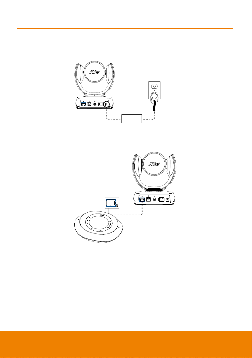
Installation
1.
Power cord
Power adapter
2.
Speakerphone
cable
speakerphone unit.
Device Connection
Connect the camera to power outlet.
Connect the camera to the speakerphone using the speakerphone cable included in the
package.
[Note]
The speakerphone port of the camera and the camera port of the speakerphone are both marked
in blue.
When connecting to the speakerphone, please remove the back port cover of the speakerphone
for successful cable connection. To remove the back port cover, simply pull off from the
9
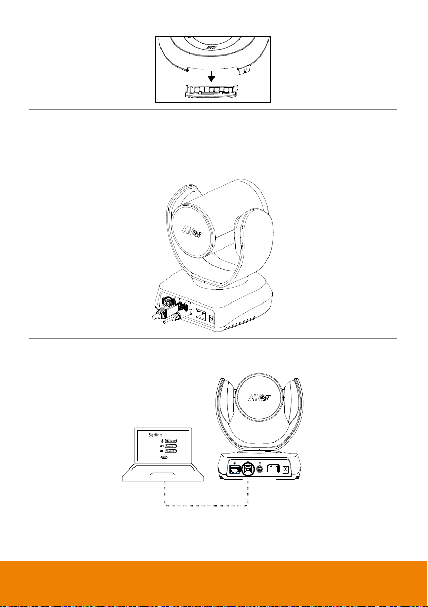
3.
4.
USB cable
Connect other necessary cables.
[Note]
USB and RS232 cable need to secure the cable with attached screw.
Make sure the cable is well connected to the connector on the camera before securing the
cable.
Connect the camera to the computer.
[Note] Use the USB 3.0 cable that is included in package.
10
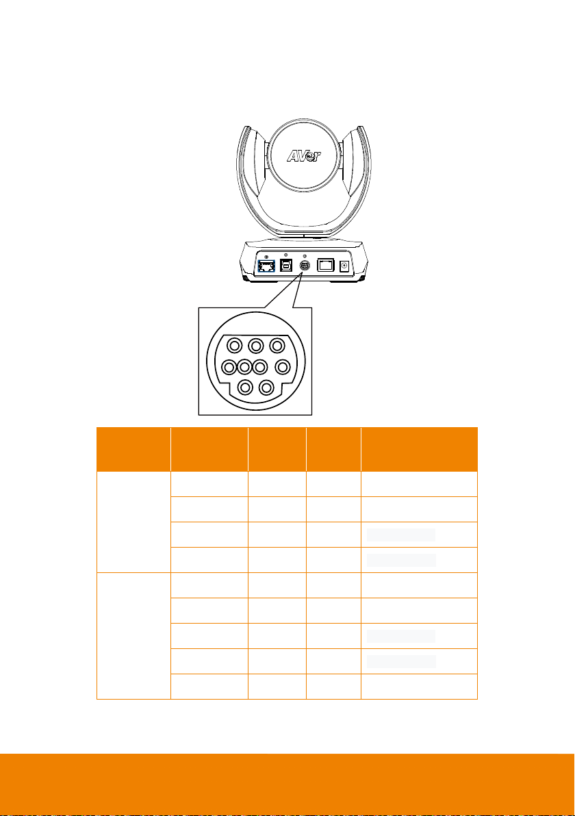
RS232 Connection
1
2
3456
789
Camera RS232 Port Pin Definition
Function
VISCA IN
VISCA OUT
Mini DIN9
PIN #
1 Output DTR Data Terminal Ready
2 Input DSR Data Set Ready
3 Output TXD Transmit Data
6 Input RXD Receiver Data
7 Output DTR Data Terminal Ready
4 Input DSR Data Set Ready
8 Output TXD Transmit Data
9 Input RXD Receiver Data
5 --- --- Not connect
I/O Type Signal Description
11
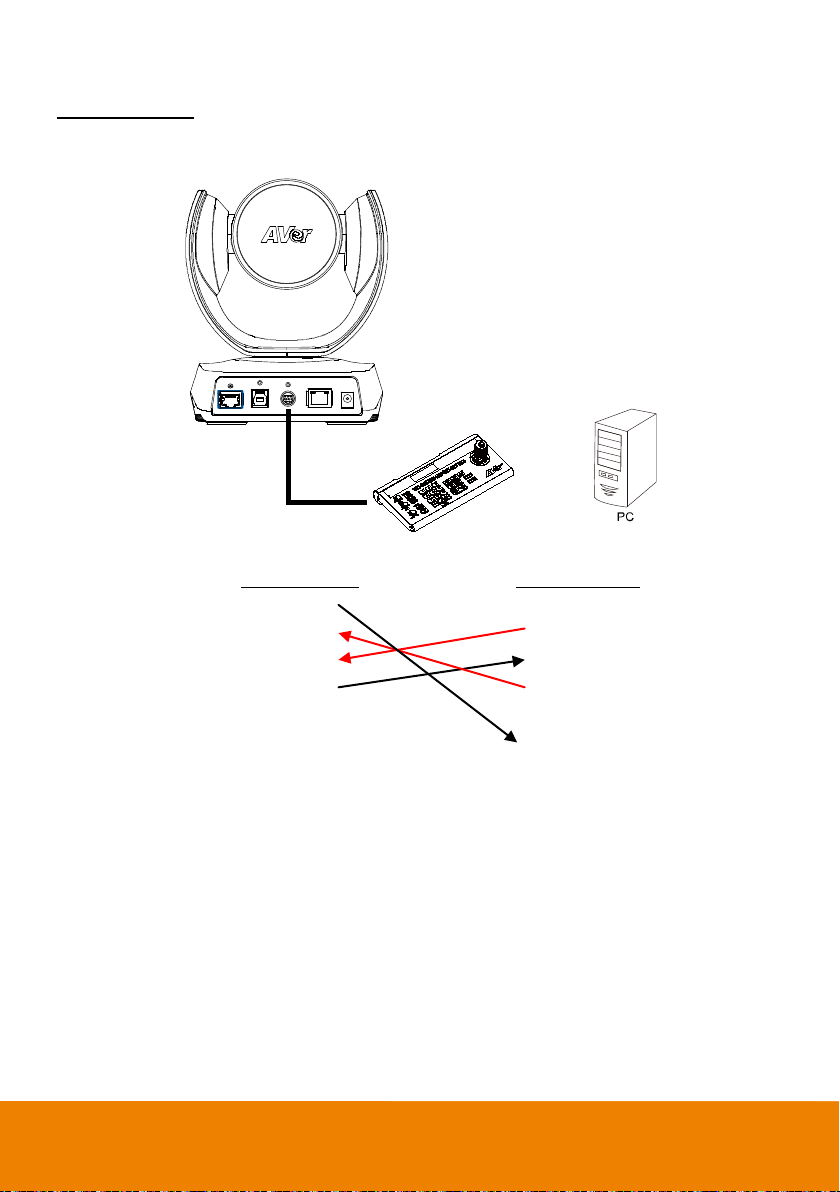
Computer/Keyboard Controller and Camera Connection
Camera controller
or
Mini DIN9 Cable
Direct Connection
If users don’t buy AVer RS232 adaptor cable, please refer to the pin connection shown below.
Camera
(Mini DIN9)
1. DTR(IN) 1. DCD
2. DSR(IN) 2. RXD
3. TXD(IN) 3. TXD
6. RXD(IN) 4. DTR
7. DTR(OUT) 5. GND
4. DSR(OUT) 6. DSR
8. TXD(OUT) 7. RTS
9. RXD(OUT) 8. CTX
9. RI
Controller/PC
(DB9)
12
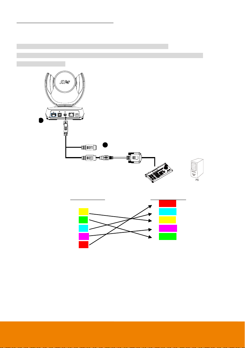
Use the RS232 mini DIN9 to mini DIN8 cable (Sold separately. Please purchase from AVer.).
VISCA in(Female)
VISCA out(Female)
Camera controller
RS232 mini DIN9
to mini DIN8 cable
or
Mini DIN8 to D-Sub9 cable
1
2
Users can purchase AVer RS232 min DIN9 to mini DIN8 adaptor cable* to connect with Computer or
keyboard/controller.
1. RS232 (mini DIN9 to mini DIN8) adaptor cable (PN: 064AOTHERCDC)
2. Users can also purchase a miniDIN8 to D-Sub9 cable to connect with camera controller.
(PN: 064AOTHERBPK)
Controller/PC
(DB9)
1. DCD
Camera
(Mini DIN8)
1. DTR(IN)
2. RXD 2. DSR(IN)
3. TXD 3. TXD(IN)
4. DTR 4. GND(IN)
5. GND 5. RXD(IN)
6. DSR 6. GND(IN)
7. RTS
8. CTX 1. DTR(OUT)
9. RI 2. DSR(OUT)
3. TXD(OUT)
4. GND(OUT)
5. RXD(OUT)
6. GND(OUT)
13
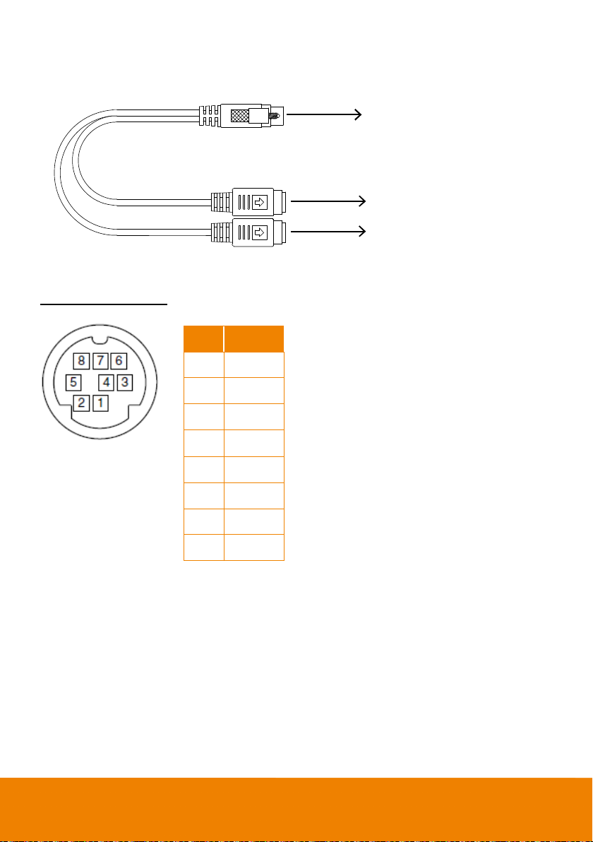
RS232 mini DIN9 to mini DIN8 Cable Pin Definition
Connect to AVer camera
Connect to next camera
Connect to controller or PC
IN(Mini DIN8)
OUT(Mini DIN8)
Mini DIN9
Mini DIN8 Pin Definition
No. Pin
1 DTR
2 DSR
3 TXD
4 GND
5 RXD
6 GND
7 NC
8 NC
14
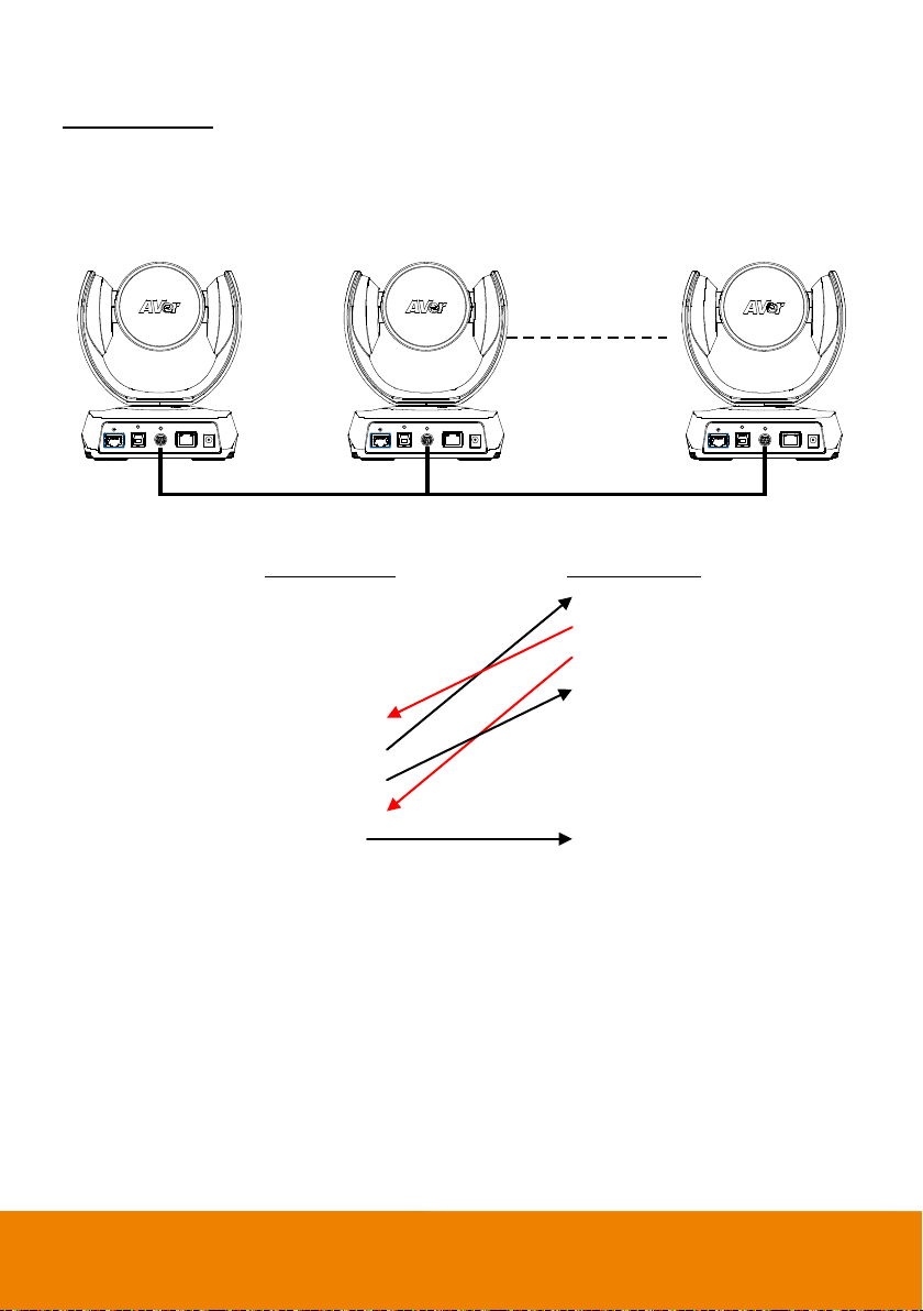
Camera Cascade Connection
1 2 7
Mini DIN9 Cable Mini DIN9 Cable Mini DIN9 Cable
Direct Connection
If users don’t buy AVer RS232 adaptor cable, please refer to the pin connection shown below for
cascading cameras.
Total can connect up to 7 cameras.
Camera 1
(Mini DIN9)
1. DTR(IN) 1. DTR(IN)
2. DSR(IN) 2. DSR(IN)
3. TXD(IN) 3. TXD(IN)
6. RXD(IN) 6. RXD(IN)
7. DTR(OUT) 7. DTR(OUT)
4. DSR(OUT) 4. DSR(OUT)
8. TXD(OUT) 8. TXD(OUT)
9. RXD(OUT) 9. RXD(OUT)
SHIELD SHIELD
Camera 2
(Mini DIN9)
15
 Loading...