

Page 1

IWH5000 series
IWH5416+16
IWH5416 Touch II
User’s Manual
v 1.1.0.0
Page 2

FCC NOTICE (Class A)
This device complies with Part 15 of the FCC Rules. Operation is subject to the
following two conditions: (1) this device may not cause harmful interference, and (2)
this device must accept any interference received, including interference that may cause
undesired operation.
Federal Communications Commission Statement
NOTE- This equipment has been tested and found to comply with the limits for a Class A digital
device, pursuant to Part 15 of the FCC Rules. These limits are designed to provide reasonable
protection against harmful interference in a residential installation. This equipment generates uses
and can radiate radio frequency energy and, if not installed and used in accordance with the
instructions, may cause harmful interference to radio communications. However, there is no
guarantee that interference will not occur in a particular installation. If this equipment does cause
harmful interference to radio or television reception, which can be determined by tuning the
equipment off and on, the user is encouraged to try to correct the interference by one or more of
the following measures:
Reorient or relocate the receiving antenna.
Increase the separation between the equipment and receiver.
Connect the equipment into an outlet on a circuit different from that to which the receiver
is connected.
Consult the dealer or an experienced radio/television technician for help.
Class A ITE
Class A ITE is a category of all other ITE which satisfies the class A ITE limits but not the class B
ITE limits. Such equipment should not be restricted in its sale but the following warning shall be
included in the instructions for use:
Warning ─This is a class A product. In a domestic environment this product may cause radio
interference in which case the user may be required to take adequate measures.
European Community Compliance Statement (Class A)
This product is herewith confirmed to comply with the requirements set out in the
Council Directives on the Approximation of the laws of the Member States relating
to Electromagnetic Compatibility Directive 2004/108/EC.
Warning - This is a Class A product. In a domestic environment this product may cause radio
interference in which case the user may be required to take adequate measures to correct this
interference.
Page 3
The mark of Crossed-out wheeled bin indicates that this product must not be
disposed of with your other household waste. Instead, you need to dispose of the
waste equipment by handing it over to a designated collection point for the recycling
of waste electrical and electronic equipment. For more information about where to
drop off your waste equipment for recycling, please contact your household waste
disposal service or the shop where you purchased the product.
DISCLAIMER
No warranty or representation, either expressed or implied, is made with respect to the contents of
this documentation, its quality, performance, merchantability, or fitness for a particular purpose.
Information presented in this documentation has been carefully checked for reliability; however, no
responsibility is assumed for inaccuracies. The information contained in this documentation is
subject to change without notice.
In no event will AVer Information Inc. be liable for direct, indirect, special, incidental, or
consequential damages arising out of the use or inability to use this product or documentation,
even if advised of the possibility of such damages.
TRADEMARKS
“AVer” is a trademark owned by AVer Information Inc. Other trademarks used herein for
description purpose only belong to each of their companies.
COPYRIGHT
© 2013 AVer Information Inc. All rights reserved.
All rights of this object belong to AVer Information Inc. Reproduced or transmitted in any form or by
any means without the prior written permission of AVer Information Inc. is prohibited. All
information or specifications are subject to change without prior notice.
Page 4
WARNING
- TO REDUCE RISK OF FIRE OR ELECTRIC SHOCK, DO NOT EXPOSE THIS
APPLIANCE TO RAIN OR MOISTURE.
- GUARANTEE BECOMES VOID IN CASE OF ANY UNAUTHORIZED MODIFICATIONS
INTO DOM CONTENTS.
- DO NOT REMOVE REMOVABLE HDD BAY SHILE SYSTEM IN USE. IT WOULD
DAMAGE DOM CONTENTS.
- DO NOT INSTALL DVR IN THE AIRTIGHT ENVIROEMENT. IT WOULD CAUSE
INSTABILITY OF THE SYSTEM.
- While transporting the DVR server to other location, we suggest removing hard disk
from DVR server to avoid the unexpected condition to damage the hard disk.
CAUTION
IF THERE IS ANY DAMAGE, SHORTAGE OR INAPPROPRIATE ITEM IN THE PACKAGE,
PLEASE CONTACT WITH YOUR LOCAL DEALER. WARRANTY VOID FOR ANY
UNAUTHORIZED PRODUCT MODIFICATION.
Caution symbol is intended to alert the user of the important installation and
operating instructions. Fail to comply may damage the system.
i
Information symbol is intended to provide additional information for the purpose of
clarification.
Manual Conventions
The following conventions are used throughout this manual
Page 5

CONTENTS
Chapter 1 Introduction ................................................................................... 1
1.1 Package Contents ...................................................................................... 1
1.1.1 IWH5416+16(32CH) .......................................................................... 1
1.1.2 IWH5416 Touch II(16CH) ................................................................... 1
1.1.3 Optional Accessories .......................................................................... 1
1.2 Hardware Introduction ................................................................................ 2
1.2.1 Front Panel ........................................................................................ 2
1.2.1.1 6HDD Bay Model ................................................................ ............ 2
IWH5416+16(32CH) .......................................................................... 2
IWH5416 Touch II(16CH) ................................................................... 3
1.2.1.2 4HDD Bay Model ................................................................ ............ 5
IWH5416+16(32CH) .......................................................................... 5
IWH5416 Touch II(16CH) ................................................................... 6
1.2.2 Back Panel(32CH/16CH) ................................................................... 8
Chapter 2 Hardware Installation .................................................................... 9
2.1 Hard Disk Installation ................................................................................. 9
2.1.1 6HDD Bay Model(32CH/16CH) .......................................................... 9
2.1.2 4 HDD Bay Model(32CH/16CH) ....................................................... 11
2.2 Connecting Device ................................................................................... 12
2.2.1 IWH5416+16(32CH) ........................................................................ 12
2.2.2 IWH5416 Touch II(16CH) ................................................................. 14
2.2.3 RS485 Cable Definition .................................................................... 16
2.3 Pin Definition of Sensor/Relay/RS485 Port .............................................. 17
2.3.1 Pin definition of Sensor and Relay ................................................... 17
2.3.2 Pin Definition of RS485 Port ............................................................ 18
Chapter 3 Setup Wizard ............................................................................... 19
System Setting Wizard ........................................................................................ 20
Network Setting Wizard ....................................................................................... 22
Display Setting Wizard ........................................................................................ 25
Storage Setting Wizard ........................................................................................ 26
Chapter 4 Using the DVR Software ............................................................. 35
4.1 Familiarizing the Functions in Preview Mode ........................................... 35
Page 6

4.1.1 Using Event Log Viewer ................................................................... 42
4.1.1.1 Using POSViewer ......................................................................... 44
4.1.1.2 Using Counting Log Viewer........................................................... 45
4.1.1.3 Using the Object Viewer................................................................ 47
4.2 Familiarizing the Buttons in Playback Mode ............................................. 49
4.2.1 To Cut and Save the Wanted Portion of the Recorded Video ........... 55
4.2.2 To Bookmark a Section of the Video ................................................ 56
4.2.3 To Search Using the Visual Search .................................................. 58
4.2.4 To Search Using the Event Search .................................................. 59
4.2.5 To Search Using the Intelligent Search ................................ ............ 60
4.3 Familiarizing the Buttons in Compact Mode ............................................. 61
4.4 Function Buttons in PTZ Camera Controller............................................. 62
4.5 Setting Up and Using the Emap ............................................................... 63
4.5.1 To Set Up the Emap ......................................................................... 63
4.5.2 To Use the Emap.............................................................................. 64
4.6 To Setup the PTZ/IP PTZ Camera ........................................................... 65
4.6.1 Setup the PTZ Camera .................................................................... 65
4.6.2 Setup the IP PTZ Camera ................................................................ 67
Chapter 5 Customizing the DVR System .................................................... 69
5.1 System Setting ......................................................................................... 69
5.1.1 To Set the POS Setting ................................ .................................... 87
5.1.1.1 General Setting ............................................................................. 87
5.1.1.2 Advanced Setting .......................................................................... 94
5.1.1.3 POS Database Setting .................................................................. 95
5.1.2 To Restore the Configuration ........................................................... 96
5.2 Camera Setting ...................................................................................... 100
5.2.1 Setup the Object Counting ............................................................. 107
5.2.2 To Setup the FaceFinder ................................................................ 109
5.2.3 Setup PTZ Tracking ........................................................................ 111
5.2.4 Create a Camera Group ................................................................. 113
5.3 Recording Setting ................................................................................... 117
5.3.1 To Mask/Shield an area on the screen ........................................... 122
5.3.2 To Playback Encrypted Video......................................................... 122
5.4 Network Setting ...................................................................................... 123
Page 7

5.5 Schedule Setting .................................................................................... 126
5.6 Backup Setting ....................................................................................... 128
5.6.1 Setup Quick Backup....................................................................... 129
5.7 Sensor Setting ................................ ................................ ........................ 130
5.7.1 To Setup External I/O Box .............................................................. 131
5.8 Relay Setting .......................................................................................... 133
5.9 Alarm Setting ................................................................ .......................... 134
5.9.1 To Setup Alarm Relay ..................................................................... 143
5.9.2 To Setup the Alarm Sound Setting ................................................. 144
5.9.3 To Setup Send E-mail Setting ........................................................ 145
5.9.4 To Setup FTP Setting ..................................................................... 146
5.9.5 To Setup Alarm Recording Setting ................................................. 147
5.9.6 To Setup SMS/MMS Setting ........................................................... 148
5.9.7 To Setup PTZ Preset Point ............................................................. 149
5.9.8 To Setup Alarm SOP: ..................................................................... 149
5.9.9 To Setup CMS Setting .................................................................... 150
5.9.10 To Setup POS Keyword Setting ..................................................... 151
5.9.11 Missing, Suspicious Object, and Scene Change Detected ............ 152
5.10 User Setting ........................................................................................... 155
Chapter 6 Playback Backup Video on PC ................................................ 157
6.1 Familiarizing the Buttons in QPlayer ...................................................... 157
6.1.1 To Cut and Save the Wanted Portion of the Recorded Video ......... 160
6.1.2 To Search Using the Visual Search ................................................ 161
6.1.3 To Search Using the Event Search ................................................ 161
6.1.4 To Search Using the Intelligent Search ................................ .......... 161
Chapter 7 Using the Remote Programs .................................................... 162
7.1 Familiarizing the Buttons in PCViewer ................................................... 163
7.1.1 PCViewer Screen ........................................................................... 163
7.1.2 PCViewer Control Panel ................................................................ 165
7.1.3 Playback Mode Control Panel ........................................................ 167
7.1.4 To Setup Remote System Setting .................................................. 169
7.1.4.1 Basic Setting ............................................................................... 169
7.1.4.2 Advance Setting .......................................................................... 171
Page 8

7.2 Familiarizing the Buttons in Remote Console......................................... 196
7.2.1 To Setup Remote Console Setting ................................................. 198
7.2.2 Familiarizing the Buttons in PTZ Camera Controller ...................... 200
7.3 Using the Remote Playback ................................................................... 201
7.3.1 Familiarizing the Buttons in Local Playback Mode ......................... 203
7.3.2 Familiarizing the Buttons in RealTime Playback Mode .................. 206
7.3.3 Familiarizing the Buttons in Download and Playback Mode ........... 209
7.3.4 To Cut and Save the Wanted Portion of the Recorded Video ......... 212
7.3.5 To Search Using the Visual Search ................................................ 213
7.3.6 To Search Using the Event Search ................................................ 214
7.3.7 To Search Using the Intelligent Search ................................ .......... 215
Chapter 8 Web Tools .................................................................................. 216
8.1 Remote iSetup ....................................................................................... 217
8.1.1 To Add DVR server......................................................................... 217
8.1.2 To Setup Remote DVR Server ....................................................... 218
8.2 Remote iBackup ..................................................................................... 219
Appendix A Registering Domain Names ..................................................... 227
Appendix B Network Service Port .............................................................. 231
Appendix C Pin Definition of Audio In Port ............................................... 232
Appendix D USB Recovery ......................................................................... 233
Page 9
i
-
If there is any damage, shortage or inappropriate item in the package contents,
please contact with local dealer.
-
Rack ear is an optional accessory.
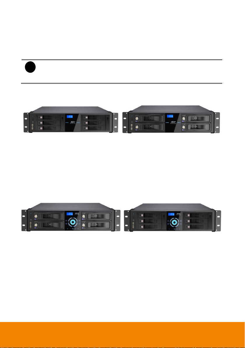
6HDD Bay model
4HH Bay model
IWH5000 series unit
Optical USB mouse
Software CD (Manual and Quick Guide are
included)
RS-485 cable
Power Cord (*The power cord may vary
according to the local electricity system.)
DVI cable (16CH)
Audio in cable (2 Spot monitor cables are
included)
4HDD bay model
6 HDD bay model
IWH5216 Touch II unit
Optical USB mouse
Software CD (Manual and Quick Guide are
included)
RS-485 cable
Power Cord (*The power cord may vary
according to the local electricity system.)
DVI cable (16CH)
Audio in cable (2 Spot monitor cables are
included)
Loop through cable(16channels)
Remote controller
Rack ears
IR Extended Cable
Chapter 1 Introduction
1.1 Package Contents
1.1.1 IWH5416+16(32CH)
1.1.2 IWH5416 Touch II(16CH)
1.1.3 Optional Accessories
1
Page 10
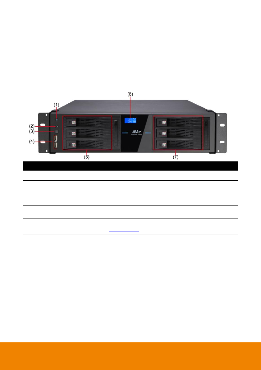
Name
Function
(1) Power
Power on the DVR unit
(2) IR Sensor port
For extended IR sensor cable(optional)
(3) IR Sensor
Receive signal from the remote control to operate the DVR
unit
(4) USB port
2 x USB 2.0 ports for connecting USB device, ex: USB pen
drive, external hard disk, mouse…and so on.
(5)&(7) Removable HDD
drawer
Each HDD bay can be installed one(1) SATA hard disk(see
also Chapter 2.1.2)
(6) LED display panel
Display current hard disk free space and system temperature.
1.2 Hardware Introduction
1.2.1 Front Panel
1.2.1.1 6HDD Bay Model
IWH5416+16(32CH)
2
Page 11
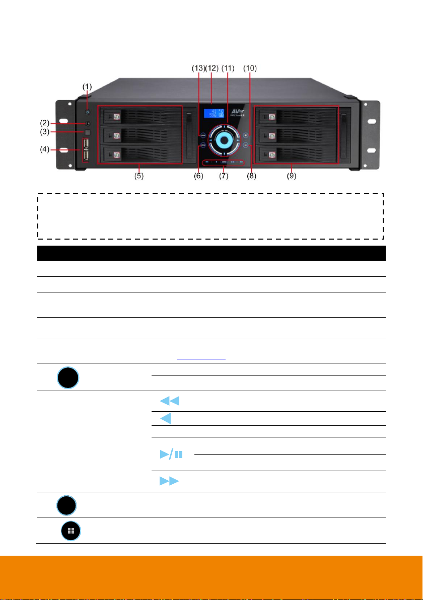
Name
Function
(1) Power
Power on the DVR unit
(2) IR Sensor port
For extended IR sensor cable(optional)
(3) IR Sensor
Receive signal from the remote control to operate the DVR
unit
(4) USB port
2 x USB 2.0 ports for connecting USB device, ex: USB pen
drive, external hard disk, mouse…and so on.
(5)&(9) Removable HDD
drawer
Each HDD bay can be installed one(1) SATA hard disk(see
also Chapter 2.1.2)
(6)
MENU
Call out system setup menu on preview mode
Call out playback menu on playback mode
(7) Playback Control buttons
To playback video at slower speed of 1/2x, 1/4x,
1/6x, 1/8x, 1/16x, or 1/32x.
To rewind the recorded video
Enter
Confirm or make a selection
To pause playback
To start playback
To playback video at faster speed of 2x, 4x, 6x,
8x, 16x, or 32x.
(8)
CH
Press the button can select channel 1, 2, 3, 4, 5… to channel
16.
(10)
Press the button can select single, QUAD, 9-split screen,
16-split screen, 7+1 split screen, and 12+1 split screen mode.
IWH5416 Touch II(16CH)
TIP
Touch the blue word, button center, blue arrow, and blue area to make a selection or
functional.
3
Page 12

Name
Function
(11)
Move cursor to left, right, up, and down
direction DVR application interface and
function setup window.
To move PTZ camera lens to left, right, up and
down in PTZ mode
Touch the blue area to go to next or
previous frame.
Go forward direction is Next frame and
backward direction is Previous frame.
(12) LED display panel
Display current hard disk free space and system temperature.
(13) Mode
Switch between preview, playback, and EMap mode.
In preview mode, user can switch between Preview,
Playback and EMap mode.
In playback mode, user can switch between Preview and
Playback mode.
In EMap mode, user can switch between Preview and
Emap mode.
4
Page 13
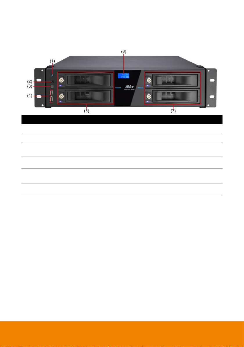
Name
Function
(1) Power
Power on the DVR unit
(2) IR Sensor port
For extended IR sensor cable(optional)
(3) IR Sensor
Receive signal from the remote control to operate the DVR
unit
(4) USB port
2 x USB 2.0 ports for connecting USB device, ex: USB pen
drive, external hard disk, mouse…and so on.
(5)&(7) Removable HDD
drawer
Each HDD bay can be installed one (1) SATA hard disk.
(6) LED display panel
Display current hard disk free space and system temperature.
1.2.1.2 4HDD Bay Model
IWH5416+16(32CH)
5
Page 14
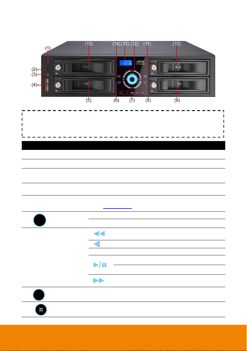
Name
Function
(1) Power
Power on the DVR unit
(2) IR Sensor port
For extended IR sensor cable(optional)
(3) IR Sensor
Receive signal from the remote control to operate the DVR
unit
(4) USB port
2 x USB 2.0 ports for connecting USB device, ex: USB pen
drive, external hard disk, mouse…and so on.
(5)&(9)&(10)&(15)
Removable HDD drawer
Each HDD bay can be installed one(1) SATA hard disk(see
also Chapter 2.1.2)
(6)
MENU
Call out system setup menu on preview mode
Call out playback menu on playback mode
(7) Playback Control buttons
To playback video at slower speed of 1/2x, 1/4x,
1/6x, 1/8x, 1/16x, or 1/32x.
To rewind the recorded video
Enter
Confirm or make a selection
To pause playback
To start playback
To playback video at faster speed of 2x, 4x, 6x,
8x, 16x, or 32x.
(8)
CH
Press the button can select channel 1, 2, 3, 4, 5… to channel
16.
(11)
Press the button can select single, QUAD, 9-split screen,
16-split screen, 7+1 split screen, and 12+1 split screen mode.
IWH5416 Touch II(16CH)
TIP
Touch the blue word, button center, blue arrow, and blue area to make a selection or
functional.
6
Page 15

Name
Function
(12)
Move cursor to left, right, up, and down
direction DVR application interface and
function setup window.
To move PTZ camera lens to left, right, up and
down in PTZ mode
Touch the blue area to go to next or
previous frame.
Go forward direction is Next frame and
backward direction is Previous frame.
(13) LED display panel
Display current hard disk free space and system temperature.
(14) Mode
Switch between preview, playback, and EMap mode.
In preview mode, user can switch between Preview,
Playback and EMap mode.
In playback mode, user can switch between Preview and
Playback mode.
In EMap mode, user can switch between Preview and
Emap mode.
7
Page 16
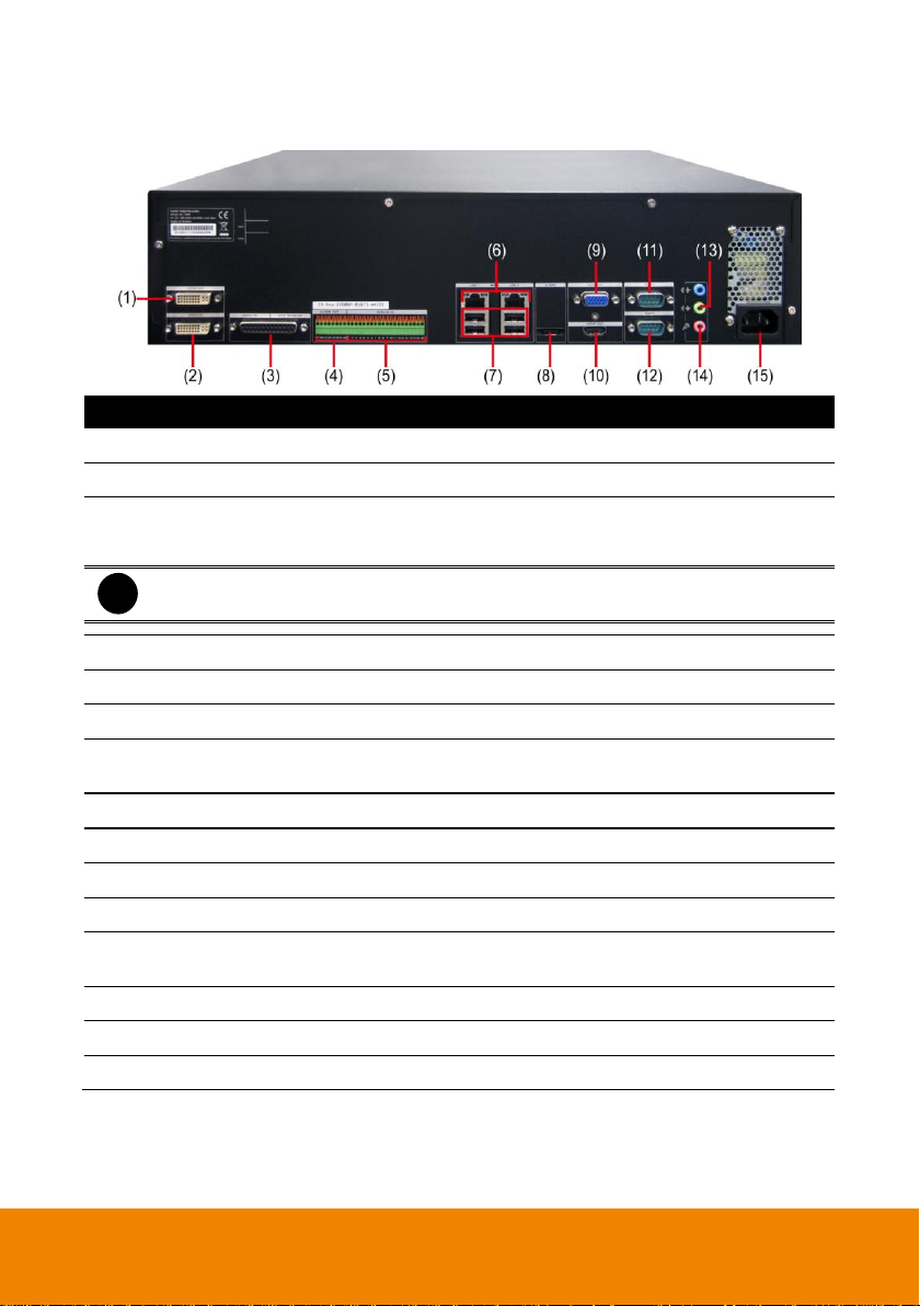
Name
Function
(1) Video Loop Out(16CH)
Output the video signal to a CCTV monitor.
(2) Video In
Input the video camera signal and display it on channel 1~ 16.
(3) Audio In & Spot Monitor
Inputs the audio signal to audio input device (16 channels) and
two (2) spot monitor output can display video on the Spot
monitor when receive an alarm video.
i
The audio input device has its own power supply is necessary.
(4) Relay Out
Support 4 relay devices (Relay: 1A @ 250V AC/30V DC).
(5) Sensor In
Support up to 16 sensor devices.
(6) LAN 1/ LAN 2 Port
For Gigabit Ethernet connection.
(7) USB port
For connecting USB interface devices such pen drive, external
hard disk, mouse, keyboard…etc.
(8) eSATA interface
For connecting with e-SATA storage.
(9) VGA Out
Output the video signal to LCD monitor.
(10) HDMI port
Output the video signal to TV/HDMI monitor.
(11) RS232 port
For POS device connection.
(12) RS485
For PTZ camera (see Appendix E) or System Controller Pro
connection.
(13) Audio output
For audio output device connection, such as speaker.
(14) MIC In
To connect the microphone.
(15) Power Plug
Connect the power cord into this port.
1.2.2 Back Panel(32CH/16CH)
8
Page 17
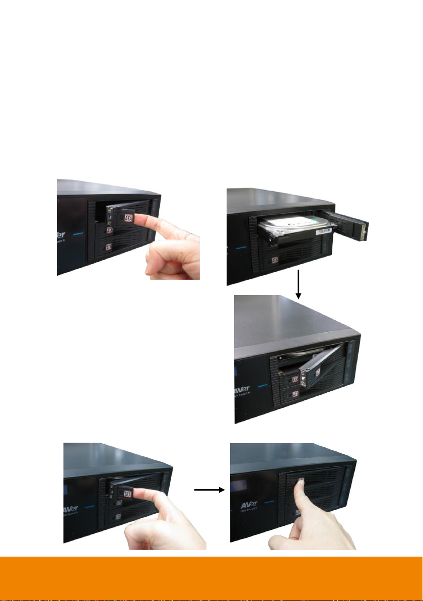
1. Open the door of HDDbay.
2. Slide the hard disk into the HDD bay and
push the hard disk inside the HDD bay
completely.
3. Close the door of HDD bay.
Chapter 2 Hardware Installation
2.1 Hard Disk Installation
2.1.1 6HDD Bay Model(32CH/16CH)
The DVR unit can support up to 4 SATA hard disks. Follow the illustrated instructions below to
install the hard disk:
9
Page 18

4. Lock the HDD bay by using the key that is included in accessories kit.
5. User may now connect all the cables and power on the DVR unit.
10
Page 19
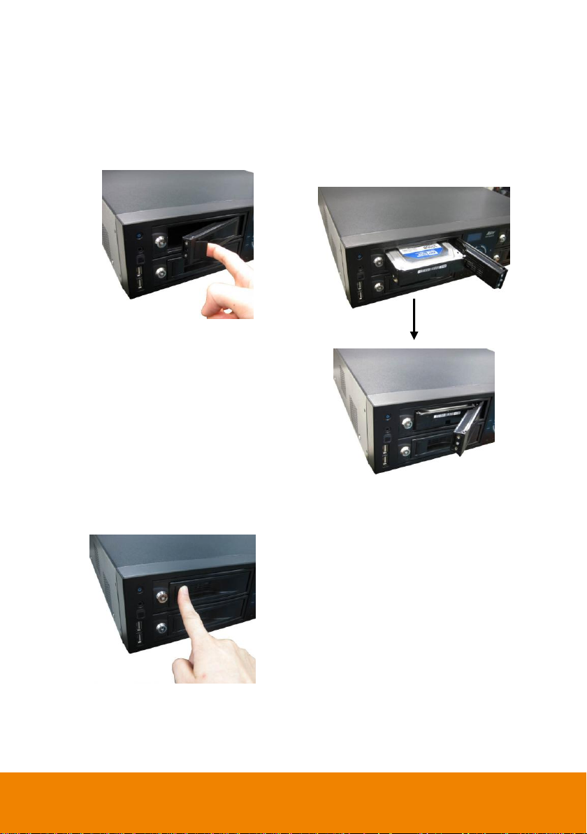
1. Open the door of HDD bay.
2. Slide the hard disk into the HDD bay and
push the hard disk inside the HDD bay
completely.
3. Push to close the door of HDD bay and
lock the HDD drawer by using the key
that is included in accessories kit.
4. User may now connect all the cables and
power on the DVR unit.
2.1.2 4 HDD Bay Model(32CH/16CH)
The DVR unit can support up to 4 SATA hard disks. Follow the illustrated instructions below to
install the hard disk:
11
Page 20
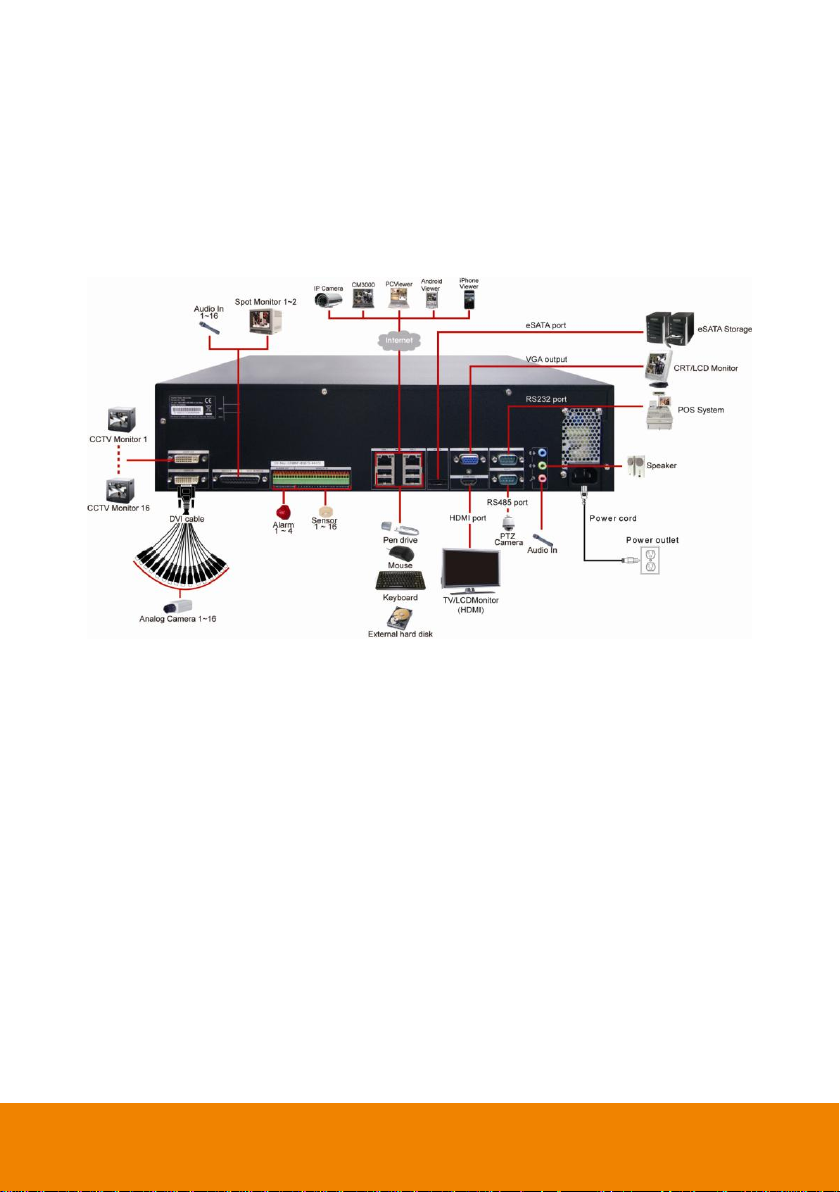
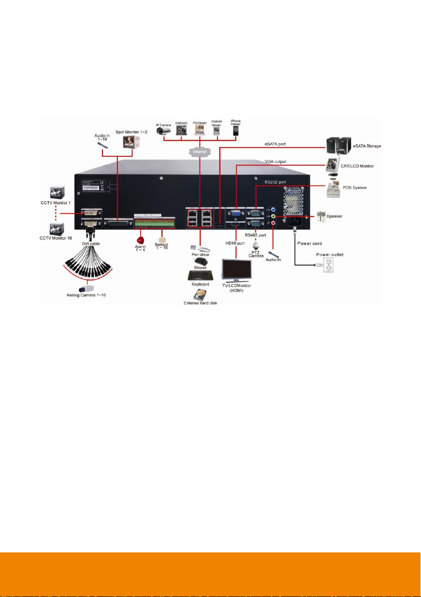
2.2 Connecting Device
2.2.1 IWH5416+16(32CH)
The back panel of the DVR unit, user can connect up to 32 cameras on both IP camera and analog
camera. The DVR unit also can connect 16 sensor devices, 4 alarm devices, and output video to
TV/LCD monitor (HDMI). Follow the illustration below to make the connection:
12
Page 21
For backup recorded video, plugging the pen drive through USB port, and then, use the bundled
software enables user to playback and export video clip.
4HDD Bay Model
6HDD Bay Model
13
Page 22
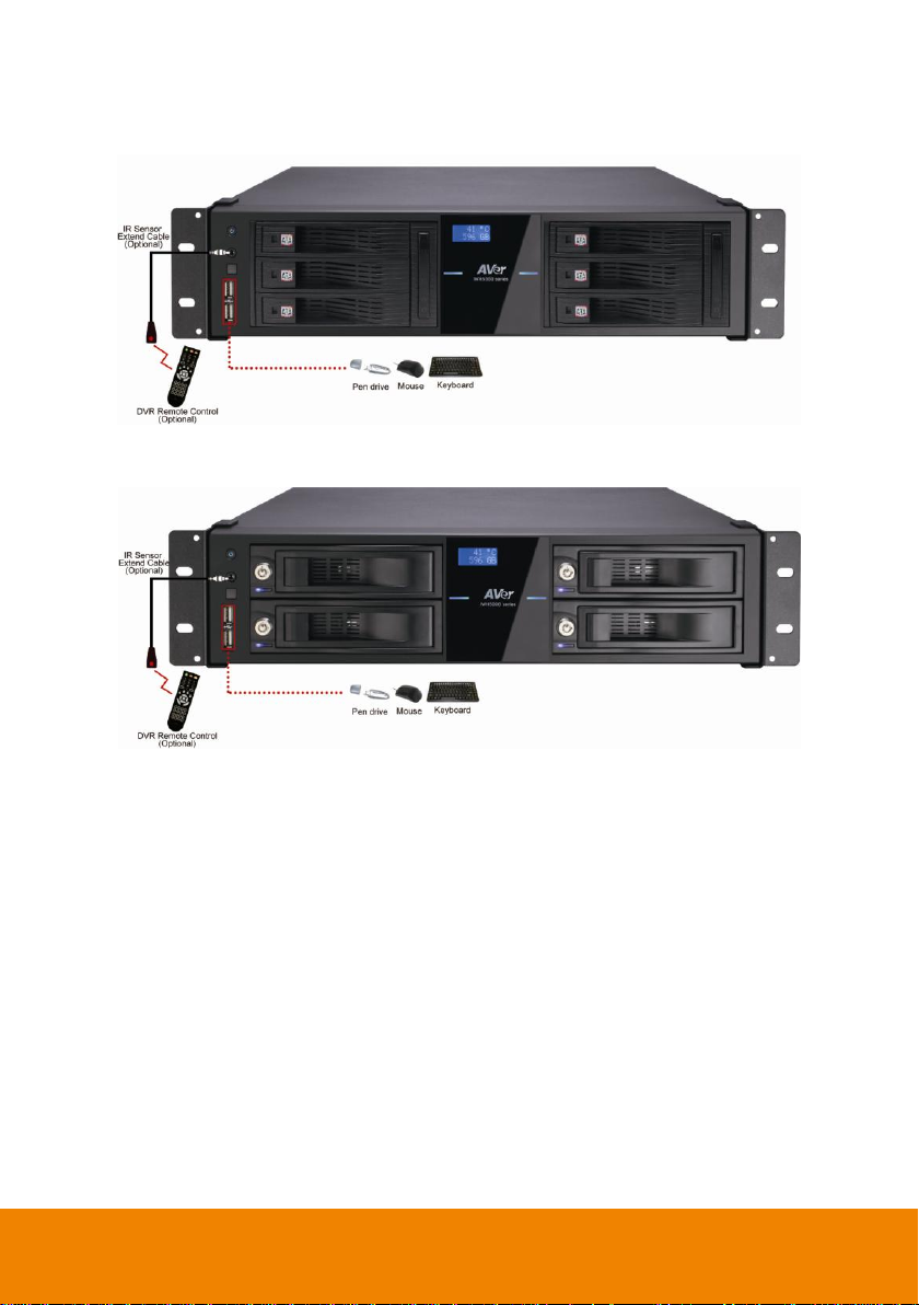
2.2.2 IWH5416 Touch II(16CH)
The back panel of the DVR unit, user can connect up to 16 cameras on both IP camera and analog
camera. The DVR unit also can connect 16 sensor devices, 4 alarm devices, and output video to 2
CRT/LCD monitor. Follow the illustration below to make the connection:
14
Page 23
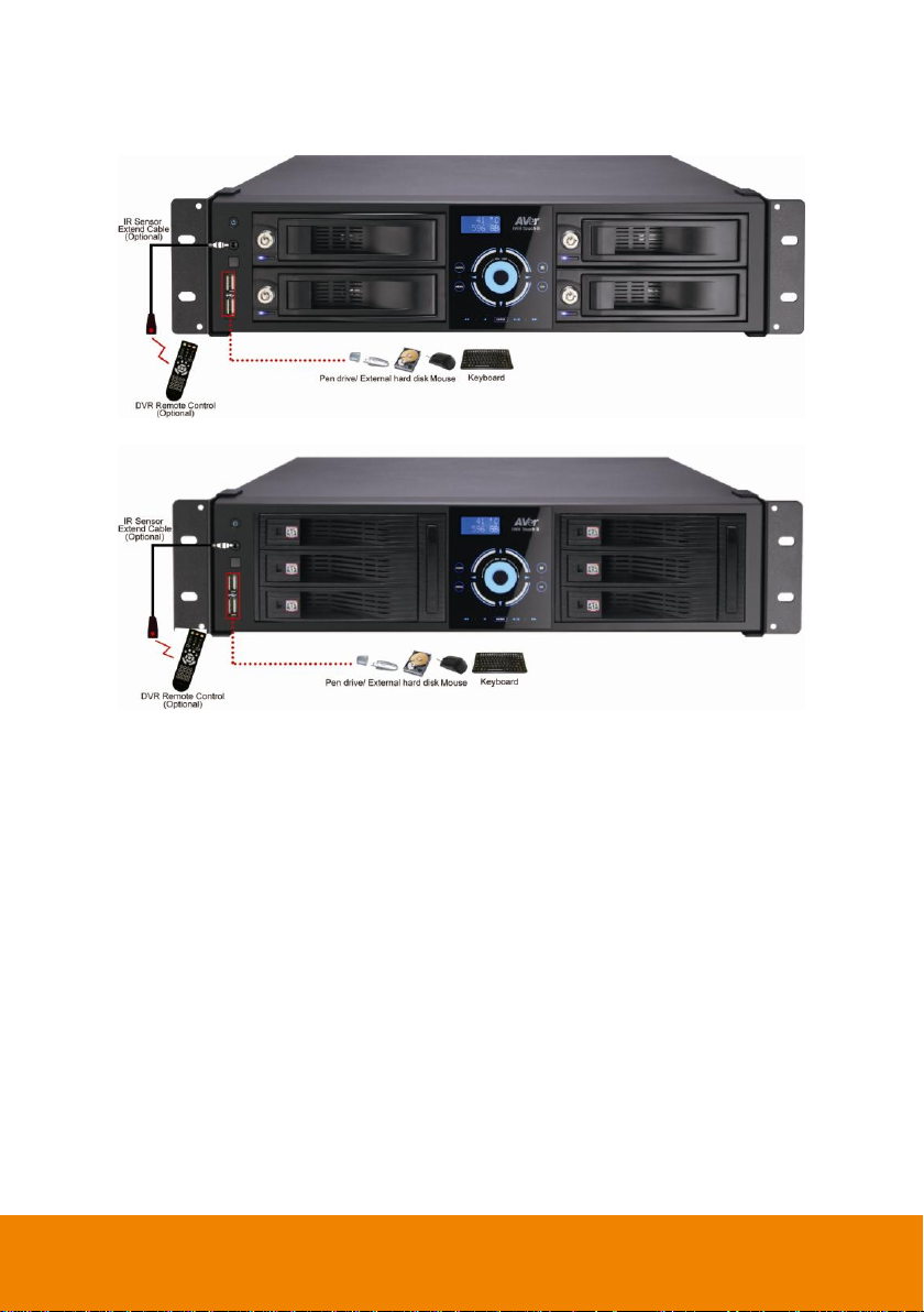
For backup recorded video, plugging the pen drive or external hard disk through USB port, and
then, use the bundled software enables user to playback and export video clip.
4 HDD Bay Model
6HDD Bay Model
15
Page 24
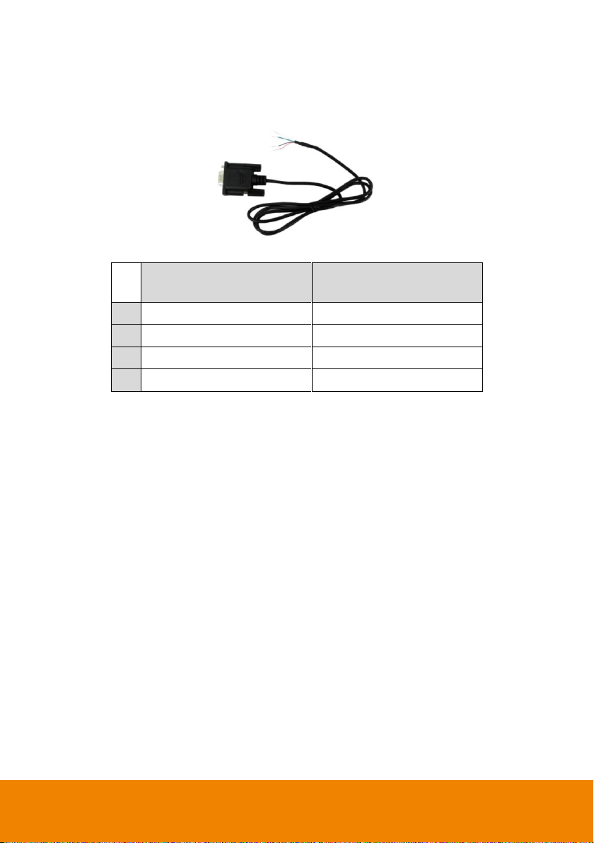
RS485 cable site
(Color of cable)
PTZ camera site
4
Red
RX+
5
Green
RX- 8 White
TX+ 9 Black
TX-
2.2.3 RS485 Cable Definition
The following list is cable definition of the RS485 cable.
RS485 cable figure
16
Page 25
#
Pin
Definition
#
Pin
Definition
1
C1
Relay Signal Close1
15 6 Sensor Signal 6
2
NO
Relay Signal Normal Open
16 7 Sensor Signal 7
3
C2
Relay Signal Close 2
17 8 Sensor Signal 8
4
NO
Relay Signal Normal Open
18 G Sensor Ground Signal
5
C3
Relay Signal Close 3
19 9 Sensor Signal 9
6
NO
Relay Signal Normal Open
20
10
Sensor Signal 10
7
C4
Relay Signal Close 4
21
11
Sensor Signal 11
8
NO
Relay Signal Normal Open
22
12
Sensor Signal 12
9 1 Sensor Signal 1
23 G Sensor Ground Signal
10 2 Sensor Signal 2
24
13
Sensor Signal 13
11 3 Sensor Ground Signal
25
14
Sensor Signal 14
12 4 Sensor Signal 4
26
15
Sensor Signal 15
13 G Sensor Ground Signal
27
16
Sensor Signal 16
14 5 Sensor Signal 5
28 G Sensor Ground Signal
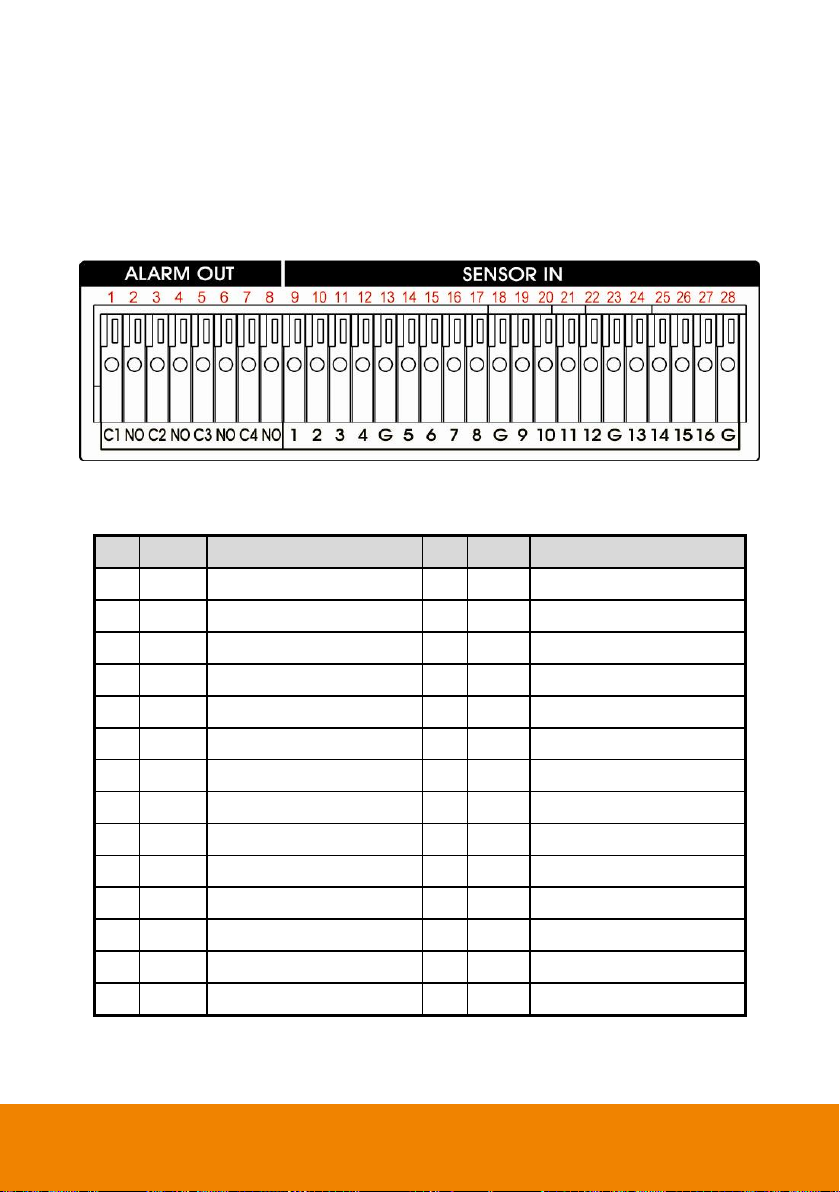
2.3 Pin Definition of Sensor/Relay/RS485 Port
2.3.1 Pin definition of Sensor and Relay
The I/O card enables you to connect 16 sensor inputs and 4 relay outputs. Just connect the
external sensor and relay pin directly to the I/O card pinhole. Check the table below and locate
which pinhole is assigned to sensor input and relay output.
The signal from the sensor (i.e., infrared sensors, smoke detectors, proximity sensors, door
sensors, etc.) is being transmitted to the I/O card and this triggers the system to respond and send
signal to relay device (i.e., alarm, telephone etc).
17
Page 26
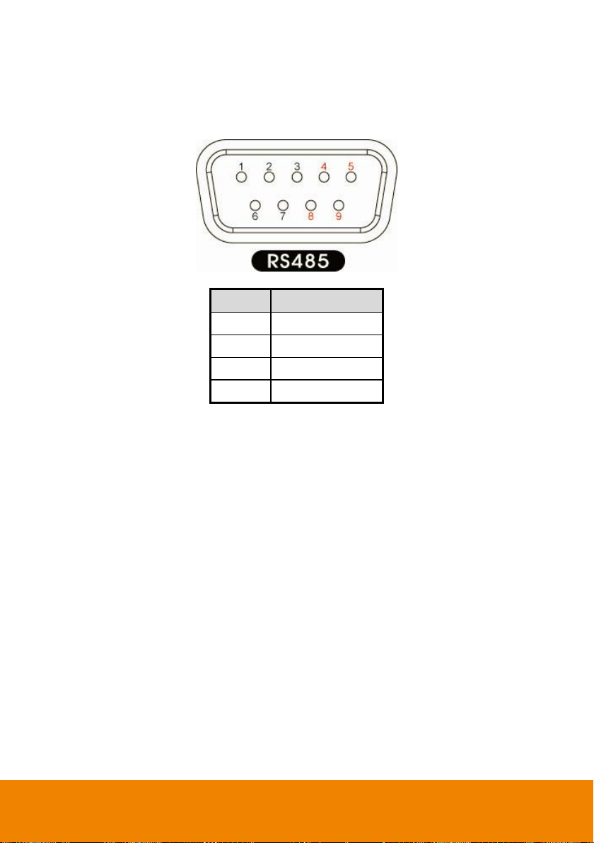
Pin #
Definition
4
RX+ 5 RX- 8 TX+ 9 TX-
2.3.2 Pin Definition of RS485 Port
The following is a pin definition of RS485 port on DVR server.
18
Page 27
i
The user can re-do the Setup Wizard by click Setting >> Setup Wizard in preview
mode.
For the first time to run
the Setup Wizard, the
selection buttons are not
allowed to select.
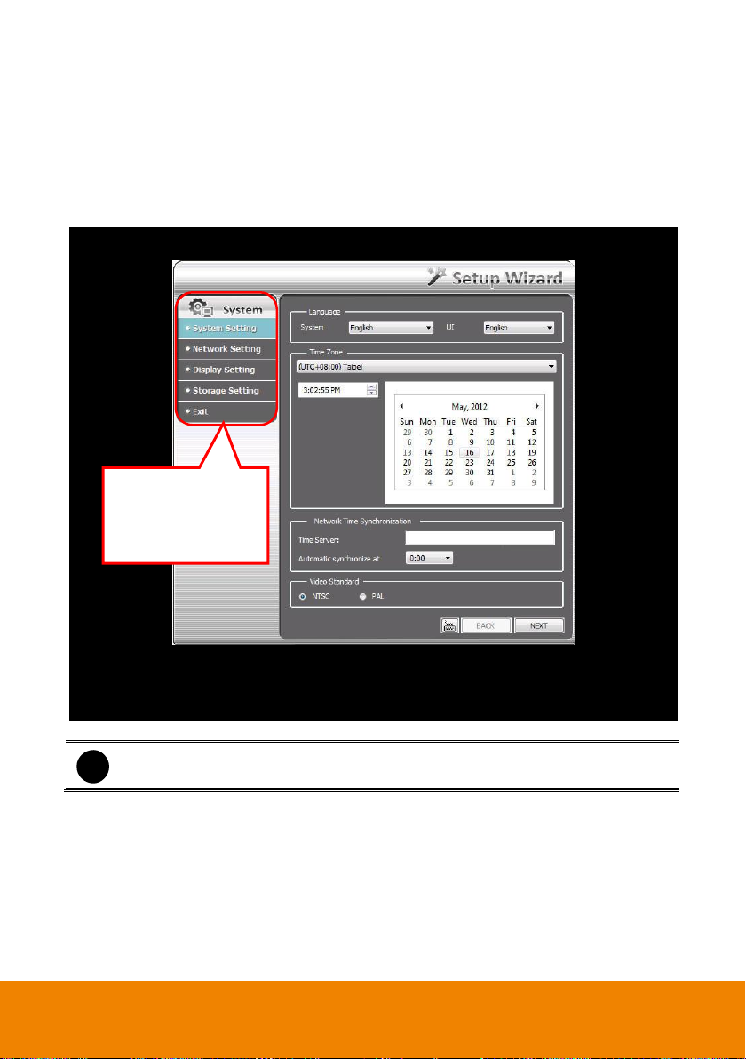
Chapter 3 Setup Wizard
For the first time to run the DVR, the Setup Wizard will guide you to setup common settings of
DVR.
After DVR system starts up, the wizard dialog is shown as following:
19
Page 28
System Setting Wizard
In System Setting step, select the language of DVR system and interface, current time zone of
DVR is located, setup network time synchronization, and select video standard of DVR system.
1. Language: Customize the language for the DVR system, interface, and tool tips based on
the selected language. The default the language is in English.
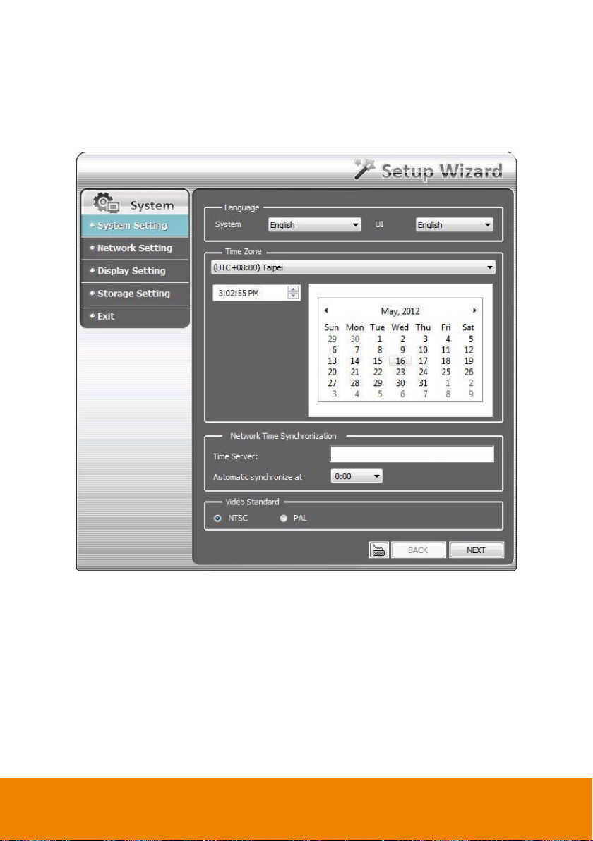
2. Time Zone: Select the time zone, time, year, and date of DVR is located to setup correct
DVR time.
3. Network Time Synchronization: Adjust the DVR system time same as network time server.
Enter the Time Server IP address or domain name. Select Automatic Synchronize time to
set automatic synchronize time on a daily basis. To adjust time manually, user need to
complete Setup Wizard and click Setup >> Setup Wizard >> System setting, then, click
Sync Now button to adjust time right away. The Sync Now button will show after completing
the Setup Wizard.
20
Page 29
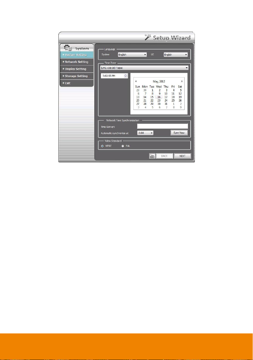
4. Video Standard: Change and select the proper video standard according to your camera
video system. If the video system setting is wrong, the video would appear abnormally.
5. Click Next to go to next wizard section.
21
Page 30
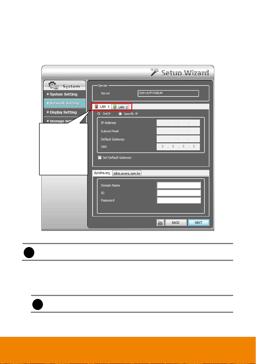
i
After setup LAN1, click Next will go to LAN2 setup page.
i
Do Not assign the DVR to 1.0.0.0 network segment. It will cause the DVR cannot
access to Internet due to the un-recognize to 1.0.0.0 IP segment.
The green light
indicates the LAN
port is connected
with Ethernet cable.
The red light
indicates the LAN
port doesn’t have
Ethernet connection.
Network Setting Wizard
Setup the IP address of DVR and configure the DDNS. After completed all configuration, click
Next to save the setting and go to next wizard setting.
1. LAN1/LAN2: Select IP address mode -- DHCP or Static IP.
DHCP: To use DHCP server assigning DVR server an IP address.
Static IP: Assign a fixed IP address for DVR server
- IP ADDRESS: Assign a constant IP address which a real IP addresses give from ISP
to DVR system.
- Mask: It is a bitmask used to identify the sub network and how many bits provide room
for host addresses. Enter the subnet mask of the IP address which user has assigned
to DVR system.
22
Page 31

i
The DDNS setting is not required to setup if user hasn’t apply your domain name yet.
- GATEWAY: A network device act as a passageway to internet. Enter the network
gateway IP address
- DNS: Domain Name Server translates domain names (such as www.abb.com.tw) to
IP addresses. Enter the IP address of DNS if it is available.
Set Default Gateway: Select LAN1 or LAN2 port as a default gateway. Only one LAN port
can be the default gateway. When user has changed the default gateway, the DVR
system will disable the previous one automatically.
2. DDNS setting: To use this feature, go to http://ddns.avers.com.tw or http://dyndns.org and
register.
dyndns.org
- Domain Name: The user has applied on website www.dyndns.org.
- ID: The account ID that user has created on website www.dyndns.org.
- Password: The password that user has setup when created an account on
http://www.dyndns.org.
dyndns.org
ddns.avers.com.tw
- Domain Name: The domain name that user has applied on website ddns.avers.com.tw.
- CD-Key: The CD-Key is located on back panel of DVR unit.
- Password: The password that user has setup when applied DNS on website
ddns.avers.com.tw.
ddns.avers.com.tw
23
Page 32

i
One of CD-Key allows user to register two domain names. One of domain name
can be used by Dispatch serve.
i
- Note that Host Name and Domain Name (avers.com) are the replacement for
Internet address while a remote client tends to search a dynamic server.
- Host Name column supports alphabet letters and number only. The maximum
character is 15.
- The password maximum character is 12.
Register the Domain Name on http://ddns.avers.com.tw
1. User Login
Browse the website ddns.avers.com.tw with Microsoft IE or Netscape Navigator to
access the following dialog.
- First input CD-Key number and select the product name.
- Then click OK to login or Reset to clear the previous input.
2. User Information
Please provide the following user information, Host Name (user can choose any
name he/she likes except the one in conflict with other users), Password, E-mail,
Company, and Country. And then, click OK to complete the domain name
registration.
Register the Domain Name on http://dyn.com/dns/
1. Open the browser on your PC and enter the URL http://dyn.com/dns/
2. Follow the DyDNS’s instruction on website to apply the free domain name.
24
Page 33

Display Setting Wizard
Set monitor resolution and frequency. The DVR system support dual monitor and user need to set
a primary monitor when using dual monitor. The preview UI is displayed on primary monitor
(Monitor 1) and the Monitor 1 sign is displayed at left-upper corner on preview UI screen. The
playback UI and Eamp UI are displayed on monitor 2 and Monitor 2 sign is displayed at left-upper
corner on screen.
Select the Resolution and Frequency from drop-down list and click Next to save the setting and
go to next wizard setting.
25
Page 34

Storage Setting Wizard
To create partition, format the hard disk and select storage path for saving recording data. Also,
user can setup iSCSI for an extra storage capability if user has iSCSI server on your LAN network.
HDD Setting: To create and format hard disk partition, delete a partition, and formatting the
hard disk.
Create a partition
1. Select the hard disk from Hard Disk Information table.
26
Page 35

2. Click on the hard disk is in Volume Information table and click Create volume to set the
size of partition.
3. User can enter the partition size or scroll the bar to adjust the size. Then, click OK to
create and format the partition. The created and formatted partition will list in Volume
Information table.
27
Page 36

4. Each partition is assigned a letter as a volume ID. When user select a storage path, please
remember the volume ID match to which partition. To select storage path, click Next to go
to Storage Setting page.
5. To create another partition, repeat the above steps.
28
Page 37

Release the partition: User can delete the partition. When the partition has been deleted,
all data save in partition will be erased
1. In Volume Information table, click Release icon ( ) of the partition that user wants to
delete it.
2. The DVR system will delete the partition and all data will be erased.
29
Page 38

Format the hard disk: To format a hard disk or a partition. All data on the hard disk or
partition will be erased.
1. Select the hard disk in Hard Disk Information table and select the partition or hard disk
that want to be format in Volume Information table.
2. Then, the Format button will show and click Format button to format it.
30
Page 39

iSCSI: To connect the iSCSI server that user has on LAN network.
1. Click iSCSI button.
2. Enter the IP address or DNS name of the iSCSI server and click Quick Connect to make
a connection to iSCSI server. After connected, user can set the iSCSI server as a storage
path.
31
Page 40

Storage Path
Set the directory on where to save the data. When there is not enough free space to record one
hour data, the system automatically replaces the oldest data. In case you have more than one
storage path, the system automatically saves the data to the next storage path.
1. Click button to select a storage path.
32
Page 41

2. In File Browser window, select the hard disk drive from Current Drive drop-down list.
3. Then, click New Folder icon to create a new folder for saving recording data.
4. Click OK to complete it.
5. A storage path will display in Storage Path table. To add another storage path, repeat
above steps. To delete a storage path, select the path and click
button
33
Page 42

6. After completing Storage setting, click Exit button and select Yes to save and exit the
Setup Wizard. If user wants to modify some of setting, select No will back to Setup Wizard.
34
Page 43

Name
Function
(1) Exit
Call up the Logout dialog box.
In the logout dialog box, you may do the following:
- Exit: To shutdown the DVR system.
- Reboot: Restart the DVR system.
- Login: To login in different account. Default user ID is admin
and password is admin.
Chapter 4 Using the DVR Software
In this chapter, it will description how to preview and playback video on DVR system. Also, it will
introduce each function in preview and playback mode.
4.1 Familiarizing the Functions in Preview Mode
35
Page 44

Name
Function
(1) Exit
- About: Display current DVR program version. User also can
update the DVR program firmware.
- Compact: Switch to compact mode
- Guest: Switch to the guest mode. In guest mode, the
functions are limited to preview and playback function only.
For complete functions of DVR, please login as an
administrator authority level.
- Cancel: To exit Logout dialog box
(2) Split Screen Mode
It provides 7 kinds of split display modes for your selection. You
can select one of the split display modes by clicking the following
icon.
i
- The 16CH DVR doesn’t support 32-split screen mode.
- If there are only 4 cameras, you won’t be able to switch to 9, 13, and 16 split
screen mode.
- The DVR system will save the current operating mode status (split screen mode,
auto scan, and compact mode status) when shutdown DVR application and apply
the mode for next login.
- When you are in single screen mode, Right click and Drag a square on the area
you want to enlarge.
- When you are in multiple-screen mode, Right click the video screen of the
camera and Drag on where you want to relocate it.
- To only display one of the video in the multiple-screen mode, Left click on the
video screen you only want to display.
(3) Record
To start recording. The button turns violet when it is recording.
Click it again and enter the password to stop.
(4) EMap
To load up to 8 desired Emaps in BMP or JPG image format, and
locate cameras, sensors, and relays to desired positions (see
also Chapter 4.5).
(5) Network
To allow inbound connections. When this function is enabled,
the button turns violet. Click it again to disable all inbound
connections.
(6) Setup
When setting up the system for the first time, type the login
password in the Password text box to access. The default ID is
admin and password is admin.
Click Setup ( ) button to configure settings for cameras,
recording, network, scheduler, backup, sensors, relays, alarms
and user authentication.
(7) PTZ
To call out a PTZ setup dialog to configure an appointed PTZ
camera (see also Chapter 4.4).
36
Page 45

Name
Function
(8) Preview
Switch to Preview mode. This allows you to view live camera
display. Press ctrl + F can freeze the live preview video screen.
And then, click Snapshot can save the freeze video screen.
(9) Playback
Switch to Playback mode. This allows you to view the recorded
video file. (see Chapter 4.2)
(10) Status Bar
It shows the current time, system temperature, and the hard
disk’s free space.
(11) Camera Group Tree
To view the user defined channel group tree (see also Chapter
5.2.4). Click “+” of group to extend group and drag the camera to
surveillance screen to view. Click “+” of camera to view the
camera information.
(12) Camera ID
Click a desired icon to play the desired channel. After you click
the icon, it turns yellow. If you assign a split display mode and
appoint a camera number, the icon group of the cameras will
turn yellow altogether.
37
Page 46

Name
Function
(13) iPOSLive
To view the real time iPOS data of channels. Click the iPOSLive
to call out the real time iPOS data windows.
DVR system supports multiple iPOS data channel display when
multi-channel function has enabled (see aslo iPOS Pro Setting
in System Setting). In default, user only can view one iPOS data
channel one at time.
To switch to different channel, click Select Camera drop down
list to select the channel. To tempore stop iPOS data coming,
click Freeze. To un-freeze, click Transaction.
(14) Snapshot
Catch a static recording image and save it as a BMP or a JPG
file.
38
Page 47

Name
Function
(15) Event log
Click it to pop-up the Event Log Viewer dialog to check Event,
Operation, POS (Point of Sales), System and Network logs. You
can select a desired date and a log item to show all logs data in
the table(see also Chapter 4.1.1 ).
(16) AutoScan
Click it to start Auto Scan.
(17) Full screen
Use the entire area of the screen to only display the video. To
return, press the right button of the mouse or ESC on the
keyboard or click the arrow icon.
When you switch to full screen in multiple-screen mode, Left
click to toggle to only display one of the video in the
multiple-screen mode or all.
(18) Alarm
Click Alarm Status ( ) button to view the status or
advanced alarm information.
39
Page 48

Name
Function
(19) Live Playback button
If user has enabled the live playback function in System setup,
the live playback icon should be seemed on the each channel
of the preview screen(see also (9) Miscellaneous in Chapter
5.1).
Click to playback the recorded file instantly in preview
mode. When the channel is in live playback mode, the icon is
. Move the mouse to the bottom of the live playback
channel, the playback tool bar
( ) will
show up. Using the playback tool bar to control the playback.
Total 4 channels can be live playback at the same time.
(20) Preview/Playback/
Emap Siwtch button
When using dual monitor, if user has enabled playback or
Emap and the Preview/Playback ( ) or
Preview/Emap( ) switch button is displayed on
preview screen.
(Preview/Playback): When the playback
screen has enabled, click the two direction arrow area ( )
that will switch playback screen to display on monitor
1(primary monitor). To switch playback screen back to
monitor 2(2nd monitor), click two direction arrow area
( ) again.
(Preview/Emap): When the Emap screen
has enabled, click the two direction arrow area ( ) that
will switch Emap screen to display on monitor 1(primary
monitor). To switch Emap screen back to monitor 2(2nd
monitor), click two direction arrow area ( )
again.
Click X to close the switch button and to call out the switch
button just enables playback or Emap again.
40
Page 49

Name
Function
(21) Volume
Adjust the audio volume to a proper volume.
(22) On Screen Keyboard
If the keyboard is not available, you may use the Virtual
Keyboard.
(23) De-interlace
To enhance the video quality. Set the de-interlace mode to #1, if
you are capturing motionless picture and #2, if it captures lots of
movement.
(24) Turbo
To improve the smoothness of live video. Turbo button is
disabled
( )
in default. When turbo button is enabled or
disabled that applies to whole DVR system, not the specific
channel. When restart or shutdown DVR system, the current
turbo status won’t be saved by DVR system
41
Page 50

i
- DVR system supports HDD failure pre-detection mechanism called HDD
S.M.A.R.T. function. Once when DVR system has detected the HDD failure
possibility, an event log will be occurred and user can check it in Event Log Viewer
window.
- The HDD S.M.A.R.T. function accurate is approximately about 60%.
- The HDD warming event log will issue once a day.
i
HDD S.M.A.R.T. warning messages’ description are as following:
- HDD warning (Low risk): abnormal situations are occurred frequently but hard disk
can recovery by itself.
- HDD warning(High risk): When HDD warring(Low risk) event has occurred too
frequently, even though hard disk can recovery by itself; however hard disk recovery
too frequently will effect performance of hard disk. Therefore, it is recommended to
replace the hard disk.
[Note] HDD S.M.A.R.T. is an accumulation mechanism, therefore the HDD warning
(High risk) event log will issue once every day until hard disk has been replaced.
4.1.1 Using Event Log Viewer
Show the record of activities that take place in the system.
42
-
Page 51

1. Click the Event Log button on DVR system main interface. The Event log viewer window will
show up.
2. Select the Date to view or search certain event log by key word. Enter the key word in Find
Text column and click Search button.
3. To filter the records, select and click the select button to display Event, System, Operation,
Network or All.
4. The event list which display on the screen can be saved as text file format. To save the event
list, click Save button.
5. To view POS event log, click POSViewer bar to call out the POSViewer window (see also
Chapter 4.1.1.1).
6. Click Counting Log Viewer to view object counting information (see also Chapter 4.1.1.2).
7. To view FaceFinder log, click Object Log Viewer (see also Chapter 4.1.1.3).
43
Page 52

(1)
(2)
(4)
(3)
(5)
(6)
(7)
Name
Function
(1) POSDB Path
The storage path for POS event log. Click to change the
storage path.
(2) Before/After
Set a time period before and after of POS event log.
(3) Channel
Select the POS event log of channel
(4) Search String
Enter specific key word or word string to search the POS event log.
Mark the “Match whole word exactly” box if wants to find exactly
key word or word string of POS event log.
(5)Export POSDB
It allows user to save the POS database to selected storage path in
excel format. Click to change the storage path. Click Export
to save the POSDB to selected storage path.
(6) Full Reception
Display the POS event log detail that user selected from Search
Result window. Click to save the POS event log. Click to
print out the POS event log.
(7) Search Result
Display the POS event log of search result. Click to save the
search result. Click to print out the search result.
4.1.1.1 Using POSViewer
44
Page 53

4.1.1.2 Using Counting Log Viewer
Click Counting Log Viewer button on Event Log Viewer window to search and view the list and
statistic report of object counting. If the object counting function is not enabling, there will be no
any data to view. To setup object counting, please refer to Chapter 5.2.1.
1. Select the Date and set a time period between After and Before for object counts searching.
2. Select the search Event – In, Out or All.
3. Select one Camera or All cameras to search.
4. Click Search to start searching.
5. The result will be list out in Result table.
6. To save the search result, click .
7. Click to print out the object counts log list.
8. To view the analysis of object counts, click Statistic Report tab.
45
Page 54

9. User can select the Date, Camera, and Cycle to view the report of object counts (In/Out).
46
Page 55

Name
Function
(1) Close
Click to close Object Log Viewer window.
4.1.1.3 Using the Object Viewer
Click Object Log Viewer button on Event Log Viewer window to view and search FaceFinder log.
If the FaceFinder function is not enabling, there will be no any data to search and view. To setup
FaceFinder, please refer to Chapter 5.2.2.
47
Page 56

Name
Function
(2) Search Mode
Switch to face object log search mode.
In search mode UI, select the Time and Camera to search the object
log. The result will display at Object Log window. Click Print button to
print out the search result.
(3) Select Camera
Select the camera to view or select all to view all cameras.
(4) Clear
To clear all object log in Object Log list.
(5) Close up
Click to close up the Object Log List window.
(6) Object Log List
Display the face object logs. It can display 32 object logs and when the
list is full, the first row of object log will be replaced.
48
Page 57

Name
Function
(1) Split Screen
Mode
Select from 6 kinds of split screen type to playback the recorded video
file of all the camera, or one camera over the other or alongside on a
single screen.
i
- If there are only 4 cameras enabled, you won’t be able to switch to 9, 13, and 16
split screen mode.
- To zoom in an area on the screen, Right click and Drag a square on the area
you want to enlarge.
(2) Exit
Close the application.
4.2 Familiarizing the Buttons in Playback Mode
To switch in Playback mode, click Playback button at the lower right corner of Preview mode user
interface
49
Page 58

Name
Function
(3) Progress bar
Show the progress of the file being played. You may move the bar to
seek at any location of the track.
When in single screen playback mode, the colors in progress bar have
different means.
Green color: a motion was detected and recorded
Blue color: is a general (always) recording file and no any event or
motion happen during recording
Red color: the sensor was triggered while recording
Black color: no record file at the time period
Yellow color: the video loss happen while recording
i
The progress bar is designed and drawn based on key frame only.
(4) Hour Buttons
Select and click to playback the recorded video file on the specific time
frame.
i
The Hour buttons represent the time in 24-hour clock. The blue bar on top of the hour
button indicates that there is a recorded video file on that period of time. While the
red bar indicates that you are currently viewing the recorded video file.
(5) Playback
Control Buttons
From left to right order:
Begin: Move at the beginning of the recorded video file.
Previous: Go back to the previous frame.
Slower: Play the recorded video file at the speed of 1/2x, 1/4x, or 1/8x,
1/16x, or 1/32x.
Rewind: Wind back the recorded video file.
Pause: Briefly stop playing the recorded video file.
Play: Play the recorded video file.
Faster: Play the recorded video file at the speed of 2x, 4x, 8x,16x or
32x.
Next: Go to the next frame.
End: Go to the end of the recorded video file.
50
Page 59

Name
Function
(6) Archive
Select the date on the calendar and the time from 00 to 23 to where to
start playing the recorded video file.
– OPEN FILE: user can open the recorded file from other storage path.
– Channel 01~ 16&Channel 17 ~ 32: Switch to different channel group
of playback calendar.
– Day Light Saving: the playback calendar will show the available
video records during day light saving time period.
i
The numbers from 00 to 23 represent the time in 24-hour clock. The numbers from
01 to 16 represent the camera ID. The blue colored column indicates that there is a
recorded video file on that period of time. While the red colored column indicates on
where to start playing the recorded video file.
(7) Status bar
Display the recorded date, time and play speed.
(8) Camera ID
Show the number of cameras that are being viewed. When you are in
single screen mode, click the camera ID number to switch and view
other camera.
51
Page 60

Name
Function
(9)iPOS Serach
To find iPOS event by keyword or period.
POSDB Path: where the iPOS data located.
Start Time: select the search start time and date
End Time: select the search end time and date
Select Camera: select the camera for iPOS events search
Keyword: enter a keyword to search iPOS event
- Match whole words exactly: the iPOS event must 100% match
the keyword that user has entered.
The search result will display in Search Result windows. User can click
specific iPOS event to view and the iPOS detail will display in Search
Receipt.
To save the search result, click Save button. Click Print button to print
the search result.
To save the selected iPOS search receipt, click Save. Click Print to
print the selected iPOS event’s detail.
52
Page 61

Name
Function
(10) Export
Export includes Snapshot, Print, Output Video Clip, and Backup
function.
Snapshot: Capture and save the screen shot either in *.jpg or *.bmp
format.
Print: Print the screen shot.
Output Video Clip: Save the segmented file in *.mpg, *.avi, or *.dvr
format (see also Chapter 4.2.1).
Backup: Save the playback file to USB device or DVD-ROM disk
(see also Chapter 5.6 Backup Setting).
(11) Segment
Keep a portion of the recorded video (see also Chapter 4.2.1).
(12) Full screen
Use the entire area of the screen to only display the video. To return,
press the right button of the mouse or ESC on the keyboard or click the
arrow icon on the screen.
When you switch to full screen in multiple-screen mode, Left click to
toggle to only display one of the video in the multiple-screen mode or
all.
(13) Event log
Show the record of activities that take place in the system. To filter the
records, select and click the option button to only display Event,
System, Operation, Network or POS.
(14) Bookmark
Mark a reference point when previewing the recorded video file to which
you may return for later reference. You may also set it to protect the file.
(See also Chapter 4.3.2)
Click to exit from full
screen mode
53
Page 62

Name
Function
(15) Visual Search
Search from a specific camera by Date, Hour, Minute, 10 Seconds and
Second. (See also Chapter 4.2.3).
(16) Find Next
Search for the next event or changes in the motion detector frame. You
can use this when you are using Intelligent Search or Event Search
function.
(17) Event Search
Search from the recorded activities that take place in the system (i.e.,
Sensor, Motion, Video Loss, POS). (See also Chapter 4.2.4).
(18) Intelligent
Search
Search the changes in the motion detector frame (See also Chapter
4.2.5).
(19) Audio
Enable/disable audio sound.
(20) Watermark
To verify the playback video has not been modified
To verify the playback video doesn’t been modified. Click to check
the video. Watermark verification window will show up as following:
i
Watermark verification doesn’t support the video that is
recorded from MPEG IP camera.
(21) De-interlace
To enhance the video quality. Set the de-interlace mode to #1, if you are
capturing motionless picture and #2, if it captures lots of movement.
(22) Turbo
To improve the smoothness of live video. Turbo button is disabled
( )
in default. When turbo buttonis enabled or disabled that applys to whole
DVR system, not the specific channel. When restart or shutdown DVR
system, the current turbo status won’t be saved by DVR system
54
Page 63

i
Right-click function is disabling for security issue.
4.2.1 To Cut and Save the Wanted Portion of the
Recorded Video
1. Use the Playback Control buttons or drag the bar on the playback progress bar and pause on
where you want to start the cut. Then, click Segment button ( ) to set the begin mark.
2. Use the Playback Control buttons or drag the bar on the playback progress bar and pause on
where you want to end the cut. Then, click Segment button ( ) to set the end mark. To
cancel segmentation or set the segment marks from the start, click Segment button ( )
again.
3. Click Export button( ) → Output Video Clip button to save the wanted clip.
4. In the Save As dialog box, locate on where you want to save the file or choose to Burn the
video segment to CD/DVD ROM (only for .*mpeg file format).
5. Select the file type and select the camera information display position when playback. The
camera information will be the information of server name that user has defined in Network
Setting.
6. If the select the file type is *.avi, user can mark Included audio to include audio in output
video segment.
7. To adjust Video Quality if needed.
8. Click Save to save the video segment.
55
Page 64

i
When the bookmark is protected, the file won’t be overwritten. The protect file can be
deleted only when the Delete the recorded data is enable in the System
setting.(also refer to Chapter 5.1 System setting)
4.2.2 To Bookmark a Section of the Video
1. Click Bookmark. The video playback stops when the bookmark button is executed.
2. In the Bookmark dialog box, you may do the following:
- Add: To include the new reference mark in the bookmark list. In Bookmark Editor window,
user can assign a name for this mark. User also can select the File protect to prevent the
bookmark file to be deleted.
- Edit: To change the mark description or enable/disable file protection.
- Delete: To remove the selected reference mark in the list.
- Delete All: To remove all the reference marks in the list.
- Exit: To close Bookmark dialog box.
56
Page 65

3. Select and click one in the bookmark list to preview the file.
57
Page 66

4.2.3 To Search Using the Visual Search
1. Click Visual Search.
2. In the Visual Search Setting dialog box, select the Camera number and the date. Then click
OK.
3. When a series of frames appear by date, click on the frame to display another series of frames
and search by every Hour of that date, every Minute of that hour, every 10 Seconds of that
minute, every Second of that 10 seconds. To go back, click . To view from the
selected frame and close event search, click .
58
Page 67

4.2.4 To Search Using the Event Search
1. Click on the video screen on where you want to search.
2. Click Event Search. The Event Search text (red) would appear at the lower left corner of the
screen.
3. In the Event Search Setting dialog box, check the type of condition you want to search. If you
select POS, in the Find Text box, type the word. Then, click OK to start searching. The video
search would stop at the frame that matches the condition. To keep on searching click Find
Next ( ) button.
4. You may also set to search and list all the result. Just check the Output Event List box. In the
Search Duration section, set the Begin Time and End Time. Set the Searching Interval time
for in a period of time won’t list out the same events. Then, click OK to start searching.
5. When the Event list appear, click and select the item you want to view.
59
Page 68

4.2.5 To Search Using the Intelligent Search
1. Click on the video screen on where you want to search.
2. Click Intelligent Search. The Intelligent Search text (red) would appear at the lower left corner
of the screen.
3. When the Intelligent Search Setting dialog box and motion detector frame appear, you may
adjust the sensitivity bar and the motion detector frame size and location. To set motion
detector frame size and location, left click and drag on the screen. Then, click OK to start
searching. The video search would stop at the frame that matches the condition. To keep on
searching click Find Next ( ) button.
4. You may also set to search and list all the result. Just check the List box. In the Search
Duration section, set the Begin Time and End Time. Set the Searching Interval time for in a
period of time won’t list out the same events. Then, click OK to start searching.
60
Page 69

Name
Function
(1) Split Screen Mode
Select from 6 kinds of split screen type to view all the camera, or
one camera over the other or alongside on a single screen.
i
- The 16CH DVR doesn’t support 32-split screen mode.
- If there are only 4 cameras enabled, you won’t be able to switch to 9, 16, and 13
split screen mode.
- When you are in single screen mode, Right click and Drag a square on the area
you want to enlarge.
- When you are in multiple-screen mode, Right click the video screen of the
camera and Drag on where you want to locate it. To only display one of the video
in the multiple-screen mode, Left click the video screen you want to display.
(2) Auto Scan
Start/Stop video screen cycle switch
(3) Alarm
Alert and display warning info.
(4) Playback
Switch to Playback mode. This allows you to view the recorded
video file. (see Chapter 4.4)
(5) Advanced
Switch to Preview/Advanced mode.
4.3 Familiarizing the Buttons in Compact Mode
To view in Compact mode, click Exit button. In the logout dialog box, click Compact.
61
Page 70

Name
Function
(1) Close
Exit PTZ camera controller.
(2) Camera preset
position number
Move the PTZ camera to the preset point.
When user select the preset point 95, a OSD panel will show out and
user can operate PTZ camera through the OSD panel. But preset
point 95 only support for Peloc-D, Peloc-C protocol.
(3) Group AutoPan
Select to automatically operate PTZ camera in group.
(4) Direction buttons’
moving speed
Adjust the moving speed of the PTZ camera lens. This speed will
apply to the (11) Direction buttons’ moving speed only.
(5) Save Camera
preset position
Save the PTZ camera preset position number. Select the camera and
click the preset position number and save it.
(6) Setup
Configure PTZ cameras (see Chapter 4.6).
(7) AutoPan
Operate the PTZ cameras automatically based on the selected
camera group preset position number. User needs to select the (3)
Group AutoPan, then, click (7)Auto Pan button.
(8) Zoom +/-
Zoom in and out the image.
(9) Focus +/-
Adjust the focus manually to produce clear image.
(10) Camera ID
Display the PTZ camera number that is being operated.
(11) Direction buttons
Move and position the focal point of the PTZ camera. The support of
direction button depends on the PTZ camera.
4.4 Function Buttons in PTZ Camera Controller
62
Page 71

4.5 Setting Up and Using the Emap
EMAP can hold up to 8 maps in *.bmp/*.jpg format. You may locate the camera, sensor and relay
on the map.
4.5.1 To Set Up the Emap
1. Click Emap.
2. When the Emap screen appears, click the area number (1 to 8 buttons) on where you want to
insert the map.
3. Click Load Map to insert the map. When the open dialog box appears, locate and select the
map and click Open.
4. When the inserted map appears on the Emap screen, click Edit. You may now drag the
camera, sensor, and relay icons to its place on the map. Icons on the map can be relocated
anywhere.
5. To set the camera direction, right click camera icon can select the camera direction in 8
angles.
6. If you are going to locate the icon on the map to other area, you need to drag the icon to the
black pane at the bottom of the Emap screen and then switch to the area on where you want to
locate the icon. To bring all the icons back to the black pane at the bottom of the Emap screen,
click Reset Icon.
7. When you are done, click Save button to save the new setting. To close Emap screen, click X.
63
Page 72

4.5.2 To Use the Emap
To use the Emap:
1. Click Emap.
2. In the Emap screen, click the camera icon to switch on the area where the camera is located
on the map and to display the video at the upper right corner of the Emap screen. At the lower
right corner of the Emap screen, it lists all the warning message.
3. To control relay, right-click relay icon and select status (on, off, or trigger) of relay.
4. To view different Emap, click Emap number button (1 ~ 8).
5. Click X to close Emap screen.
64
Page 73

i
- The numbers of preset position are depended on the IP camera protocol has
supported.
- Only Pelco-P and Pelco-D protocol can support over 16 PTZ preset points.
- Only Canon has supported “Auto Pan Speed” function.
Using this control
panel to set the
preset position
4.6 To Setup the PTZ/IP PTZ Camera
4.6.1 Setup the PTZ Camera
1. In the PTZ control panel, click Setup.
2. When the PTZ Setup dialog box appears, select the camera number and check the Use PTZ
box.
3. In the Connection Settings section, select the COMPort where the PTZ camera is
connected, PTZ ID number, BaudRate, and Protocol. Then, click Save to keep the settings.
4. Use the PTZ control panel and adjust the position of the PTZ camera.
5. In the Preset Setting section, select the preset number to assign a number for the PTZ
camera current position. Set the DwellTime (1-60 sec) for how long the PTZ camera stays in
that position before it moves to the next one. If you want to add description, check the Show
Preset Name box and in the Preset Name text box, type the word. When done, click Save to
keep the settings.
65
Page 74

i
- User can move the on screen PTZ controller to any position of screen
- The on screen PTZ controller only display on a channel screen at a time.
6. Repeat step 4 & 5, if you want to save another PTZ camera position.
7. Restore AutoPan Time: set a time period for restoring auto path function after the PTZ
camera has been moved. Mark the check box and set the time period in second.
8. Using Joystick: Mark to enable for joystick device.
9. Show moving direction indicator line: enable/disable to show the direction line when uses
mouse drag on screen in PTZ mode.
10. Iris: To adjust the iris of PTZ camera. It may not support that depends on brand of the PTZ
camera.
11. OSD: To allow call out PTZ camera factory’s OSD setup menu. The OSD setup menu may
vary that depends on the brand of PTZ camera.
12. When is done, click OK to save the setting or Click Cancel, to leave without saving the new
setting.
13. When PTZ camera is enabling, user can control PTZ camera by using the PTZ control panel
and on screen PTZ control bar.
14. Select the PTZ camera channel and click PTZ button on preview UI to call out PTZ control
panel. PTZ control panel function refers to Chapter 4.4.
66
Page 75

i
- The numbers of preset position are depended on the IP camera protocol has
supported.
- Only Pelco-P and Pelco-D protocol can support over 16 PTZ preset points.
- Only Canon has supported “Auto Pan Speed” function.
4.6.2 Setup the IP PTZ Camera
1. In the PTZ control panel, click Setup.
2. When the PTZ Setup dialog box appears, click IP PTZ tab.
3. Select the camera number and check the Use PTZ box.
4. In the Connection Settings section, select the Protocol and Model of PTZ camera that user
wants to connect and enter the IP or URL of IP camera in IP Camera Site column. Mark the
Authentication box if ID and Password is required when connecting to IP PTZ camera. And
then, click Save to keep the settings.
5. In the Preset Setting section, use the PTZ control panel and adjust the position of the PTZ
camera and select the preset number to assign a number for the PTZ camera current position.
6. Set the DwellTime (1-60 sec) for how long the IP PTZ camera stays in that position before it
moves to the next one. If you want to add description, check the Show Preset Name box and
in the Preset Name text box, type the word. When done, click Save to keep the settings.
7. Repeat step 5 & 6, if you want to save another IP PTZ camera position.
8. Restore AutoPan Time: set a time period for restoring auto path function after the IP PTZ
camera has been moved. Mark the check box and set the time period in second.
67
Page 76

i
- User can move the on screen PTZ controller to any position of screen
- The on screen PTZ controller only display on a channel screen at a time.
9. Using Joystick: Enable/disable Using Joystick such as USB joystick device.
10. Show moving direction indicator line: enable/disable to show the direction line when uses
mouse drag on screen in PTZ mode.
11. Iris: To adjust the iris of IP PTZ camera. It may not support that depends on brand of the PTZ
camera.
12. OSD: To allow call out IP PTZ camera factory’s OSD setup menu. The OSD setup menu may
vary that depends on the brand of IP PTZ camera.
13. When is done, click OK to save the setting or Click Cancel, to leave without saving the new
setting.
14. When PTZ camera is enabling, user can control PTZ camera by using the PTZ control panel
and on screen PTZ control bar.
15. Select the PTZ camera channel and click PTZ button on preview UI to call out PTZ control
panel. PTZ control panel function refers to Chapter 4.4.
68
Page 77

Chapter 5 Customizing the DVR System
In the Preview/Advanced screen mode, click button to customize your DVR. When the
DVR configuration setup selection appears, select and click the buttons you want to change the
setting.
User can re-do the Setup Wizard by clicking Setup Wizard bar.
5.1 System Setting
In the System Setting dialog box, click OK to accept the new settings, click Cancel to exit without
saving, and click Default to revert back to original factory setting.
(1) Storage Path
Set the directory on where to save the data. When there is not enough free space to record one
hour data, the system automatically replaces the oldest data. In case you have more than one
storage path, the system automatically saves the data to the next storage path. You may also add
additional network-attached storage (NAS) for extremely high storage capacity(see also Map
69
Page 78

Network Drive in (13)System Configuration).
To insert another storage path, click Add. To remove the selected path, click Delete. If you want
the system to automatically erase the data after a certain days, enable the Delete recorded data
after check box and enter the numbers of days in Days text box. If you want the system to
automatically erase the event and alarm log after a certain days, enable the Delete event and
alarm log after check box and enter the numbers of days in Days text box. To change logs save
direction, enable Move to and select the new save direction.
(2) Hard Disk Calculator
Estimate the hard disk recording capacity. The result of
calculation is a rough value which only for reference.
The hard disk record capacity will be varied by the real
record quality and complexity of video scene.
Click , the hard disk calculator windows will show
up. Total Recording time is the current hard disk
recording capacity. Enter the expect hard disk size or
expect recording time in Expected HD Size or
Expected Record time, and then click Calculate
button. Click OK to exit the hard disk calculator
windows. The hard disk calculation will base on the
recording setup and current hard disk setup, therefore,
starting record before use Hard disk calculator function.
(3)Language
Customize the system to display the system, interface, and tool tips based on the selected
language. By default the language is in English.
(4) Video Standard
Change and select the proper video system according to your camera video system. If the video
system setting is wrong, the video would appear abnormal.
(5) Attention Please
Check the attentiveness of the person who is monitoring the system. You may set the number of
times the Attention dialog box to appear in a day in Times per day text box. To check the graph on
how fast the person response, click Analysis.
When this feature is enabled, the Attention dialog box would appear. The person who is monitoring
the system must enter the same number that appears from the left box at the right text box and
then click OK.
70
Page 79

i
The DVR system supports both analog and IP camera channel on TV output.
(6) TV Out
Select the camera you want to appear on TV and set the time gap from 3 to 10 sec. before it
switches to the next camera.
- Advance: Select the video card channel and camera that user wants to display on TV. In
Advance mode, user has two types of display selection – Autoscan and Fixed layout.
Autoscan
(1) The video source.
(2) Select the display mode as Autoscan.
(3) Preview screen: Live camera video would be displayed here.
(4) View Mode: Select the video mode user wants to display on screen. The system will
auto cycle switch to display the next channels.
(5) Cameras: User can select the cameras that user wants to display on the screen. Only
those selected cameras would be displayed on the screen. Also, the camera will be
displayed by the selecting order.
71
Page 80

Fixed Layout
(1) The video source.
(2) Select the display mode as FixedLayout.
(3) Preview screen: the selected camera video will preview in here.
(4) View Mode: Select the split mode of TV out display.
(5) Cameras: User can select the cameras that user wants to display on the screen. Only
those selected channels would be displayed on the screen. Also, the camera will be
displayed by the selecting order.
(7) Configuration
Backup a copy of all the settings and allows you to regain the same settings back. To save the
current settings, click Export. To replace the settings with the one you have saved, click
Import(see also Chapter 5.1.2).
(8) Login
Enable the conditions in Login section you want the system to automatically carry out.
- Auto record when login
Automatically start video recording when the DVR system is executed.
- Auto start Network when login
Automatically enable DVR network connection when login into DVR program.
- Login to compact mode
Switch to compact mode directly when the DVR system is executed.
- Guest Mode
Automatically log in Guest mode when the DVR is executed. In guest mode, the functions are
limited to preview and playback only.
72
Page 81

- Default user
Automatically log in to the selected default user when the DVR system is executed.
(9) Miscellaneous
Enable the conditions in Miscellaneous section you want the system to perform.
- Status Report
Send a daily system event and attention analysis report. To change the e-mail settings, click
Setup.
- Beep if no signal
Make sound when the video signal is lost.
- Mandatory Record
Always record video when software is running.
- Enable Liveplayback
To allow instantly live playback while recording in preview mode (see also (19)Live playback in
Chapter 4.1).
- Screen Saver
Set a period time to enter screen saver mode when system idle.
- Leave the system without asking user name and password
Don’t need to enter password when close/exit DVR program.
73
Page 82

i
To disable the dual monitor function when only has connected one monitor. Otherwise,
the Playback UI won’t be able to display on main monitor screen (monitor 1).
- Resequence channels when autoscan
The DVR system will re-arrange the channels order if some of channel is disable when auto
scan is enabled. For example, CH 1 and 3 is disable, the channel will display in order of
CH2,4,5,6,7~16. The CH1 and 3 won’t be shown on screen when auto scan is enabled.
- Remember playback display mode
To memorize the last playback status. The DVR system will memorize the playback status
from last time that user has selected or setup for next time playback.
- Enhance IP camera performance in TV out
Mark to improve the IP camera video preview smoother on TV output.
- Auto Scan Period
Set the time gap of the Auto Scan function from 3 to 10 seconds. This automatically switches
to the next video in cycle depending on the set time gap.
- Temperature Display
Select the format of temperature -- °C or °F
- Playback Mode
Select the mode of playback the video.
Select date and time: Select the date and time which user wants to playback.
Play the last file: Automatically playback the video from the last hour
Instant Playback: Automatically playback the video which has just recorded. To set the
instant playback time period, fill in the time in second at Set Instant Playback’s Play
Time column.
- Date Format
Select the date format which wants to display in Select date and time playback mode
(10) Dual Monitor
Mark to enable the Playback UI and Emap UI to display on 2nd monitor (monitor 2). In default, DVR
system only display on one monitor (monitor 1) but the dual output is available.
(11) POS
Set from which camera screen to display the data from the POS equipment. Click Setting, to set
the POS Console Setting. (see also Chapter 5.1.1)
74
Page 83

(12) UPS (Uninterruptible Power Supply)
Protect the system from damaging, such as power surges or brownouts. This automatically gives
time to close the DVR system properly when the battery backup power has reached the Shutdown
when capacity below percentage level setting. The UPS device must be connected to your
computer.
(13) System Configuration
In System Configuration section, user can setup keyboard language, printer, PPPoE setting, Audio,
Phone and Modem, Map/Disconnect network drive, and view use information of CPU, Network,
Memory, Camera, and HDD S.M.A.R.T.
75
Page 84

Usageinfo
To view usage of the system CPU, memory, and network.
CPU
Displays DVR system’s CPU usage.
Memory
Displays DVR system’s memory usage.
76
Page 85

Click drop-down list to select
LAN2 and view LAN2 usage
information.
Network
Displays DVR system’s network usage.
CameraInfo
Displays DVR system’s cameras information – Camera name, ftp in Live and Recording, and
current status. In Status, a is analog camera channel, IPCam is IP camera channel, w is
remote DVR camera channel.
77
Page 86

Double-click on hard disk to
view detail information of
hard disk.
Description of Status – Good,
Low risk, High risk, Not
support.
S.M.A.R.T
Displays DVR system’s hard disk information. User can view information of each hard disk or
hard disk portion on DVR system.
78
Page 87

Keyboards/Input methods
Select the keyboard or input language.
PPPoE Setting
To configure the LAN setting of DVR system.
1. Click PPPoE Setting.
2. Then, the DVR system will require rebooting the DVR system for PPPoE setup. Click OK to
reboot the DVR system.
79
Page 88

3. After DVR system reboot, Click Setup >> System >> System Configuration >> PPPoE >>
Add button >> Broadband(PPPoE)
80
Page 89

4. Enter the PPPoE’s User name and Password. Mark Remember this password and keep
Connection name as default -- Broadband Connection. Then, Click Connect to make a
connection
81
Page 90

5. After PPPoE connect successful, click Close button.
6. User will see the name of PPPoE connection that user has setup list in Dial-up and Virtual
Private Network settings.
7. Then, click OK and reboot the DVR system.
8. If have any configuration problem, please advised the network administrator for suggestion.
82
Page 91

Sounds Setting
Adjust audio volume of system.
Printer
Click Add Printer and following the wizard to install a printer.
83
Page 92

Device Management
To manage the DVR system devices.
Phone and Modem options
To setup the modem dial-up settings.
84
Page 93

Map Network Drive
To add network storage, the Internet storage drive/folder must be mapped as Network Driver in
DVR server. Follow the below steps to map the network drive.
1. Click Map Network Drive button. In the Map Network Drive windows, select the Drive and fill
in the IP address and file folder of file server or NAS on your network in Folder.
2. And then, click Finish to make the connection.
3. After connection successful, user should see the network drive on the Storage Path.
Disconnect Network Drive
To disconnect the mapping network drive, click Disconnect Network Drive.
85
Page 94

i
Only when System Controller is using RS485 port connect to DVR server, the port
needs to be selected.
(14) System Controller Setup
To configure the parameters that is for communicating with the System Controller (an optional
accessory). Also please refer to user manual of the System Controller. How to operate the System
Controller, please refer to the user’s manual of the System Controller.
Enable – Mark the check box to enable the System Controller function.
Upgrade – To update the firmware of the System Controller.
Model – Select model of the System Controller. If System Controller is connecting to DVR
through the USB port, please select the System Controller Pro mode. If System Controller
is connecting to DVR through the RS485 port, please select the System Controller Pro 485
model.
Port – Select the com port that is connected with the System Controller Pro.
ID – Set an ID for DVR server (0~99). This ID is a key for the System Controller to control the
DVR server when there are more than one DVR servers are connecting with the System
Controller through the RS485 port
86
Page 95

5.1.1 To Set the POS Setting
5.1.1.1 General Setting
1. In the System Setting dialog box, POS section, click Setting.
2. In the POS Console Setting dialog box, click Add to set a new POS setting, Modify to change
the POS setting, and Delete to remove the selected POS setting. Click OK to save and close
POS Console Setting.
3. In the POS Mapping dialog box, click OK to accept the settings and Cancel to exit without
saving the new setting.
87
Page 96

(1) Name: Enter a name to identify the POS.
(2) Protocol: To select the protocol, click Setting button (see Setup POS Device)
(3) Skip first: Set the number of lines you want to be removed
(4) Start Testing: Click to test POS setting. You will see a test result on the right side of
POS Mapping window.
(5) Port Setting: Select the Local or Remote port to where it is connected.
Local: Select the COM port number which is connected.
Remote: Use the UDP protocol for remote connection if POS
system can broadcast to Internet. Enter the IP
address of the remote station.
(6) Setup…: Set the COM Properties. If you are not sure, please contact your POS
service provider.
(7) Map to Channel: Select to which camera number to display the transaction text.
(8) Text Filter: Enter the word you want to be removed.
88
Page 97

Setup POS Device
There are some default POS devices. If user uses the POS device beside defaults, user can add
new POS device and rules. The POS device can be added up to 50 include defaults.
Setup Standard POS Device
Add New POS Device
1. Click Add
2. Enter the POS device name in Name column
3. Select the Type as Standard
4. Click OK to save
5. To modify existing device, double click it.
6. Click Default can be reset back to original setting.
89
Page 98

Add Rules
1. Select the POS device form device list
2. Click Add in Rules section
3. In Rule Setting windows, select Group. Each group has a limited number of times ; please
refer to the “Maximum” and “Remainder” information in Rule Setting windows. The Line End,
Page End, and Bill End group only can be set once.
- Line End: set a rule to separate each line.
- Page End: set a rule to switch page.
- Skip Cmd: set a rule to discard a string or character.
- Include: set a rule for a lime with a string or character to be displayed.
- Exclude: set a rule for a line with a string or character to be concealed.
- Bill End: set a rule to divide each transaction.
4. Select Type – Ascii or XML
5. Enter the string or character as the rule in Data column. The maximum length is 31 characters.
6. Click OK
7. Click Save. The configuration will be lost without saving.
8. To modify existing replace rules, double click it.
Character Replacement
Set a rule to replace a character or word in POS data. The maximum replacement is 8.
1. Select a POS device from device list
2. Click Add in Replace section
3. Old Data: select the Type(Ascii or Hex) and enter word or character that wants to be replaced
4. New Data: select the Type (Ascii or Hex) and enter the word or character that will replace it in
Old Data.
5. Click OK
6. Click Save. The configuration will be lost without saving.
7. To modify existing replace rules, double click it.
90
Page 99

Adjust Rule Priority
User can set the priority of rule groups. Select the group and click up/down arrow button to move
the priority level. The upper position, the priority is higher.
91
Page 100

Setup XML POS Device
XML can only work with the POS data is transmitting in XML format.
Device: select or add a new device. Only device that supports XML can be configured in here.
Click Add to add a device. Enter device name and select Type as XML. The POS device can
be added up to 50 include defaults.
Page Start: Beginning of data for transaction
Page End: End of data for transaction
92
 Loading...