

Page 1

IWH3216 Touch/Touch II
16CH Embedded Hybrid DVR
Quick User Guide
Page 2

COPYRIGHT
© 2012 AVer Information Inc. All rights reserved.
No part of this document may be reproduced or transmitted in any form, or by any means without the
prior written permission of AVer Information Inc. AVer Information Inc. reserves the rights to modify
its models, including their characteristics, specifications, accessories and any other information
stated herein without notice. The official printout of any information shall prevail should there be any
discrepancy between the information contained herein and the information contained in that printout.
TRADEMARKS
“AVer” is a trademark owned by AVer Information Inc. Other trademarks used herein for description
purpose only belong to each of their companies.
NOTICE
SPECIFICATIONS ARE SUBJECT TO CHANGE WITHOUT PRIOR NOTICE.
THE INFORMATION CONTAINED HEREIN IS TO BE CONSIDERED FOR REFERENCE ONLY.
WARNING
TO REDUCE RISK OF FIRE OR ELECTRIC SHOCK. DO NOT EXPOSE THIS APPLIANCE TO
RAIN OR MOISTURE.
WARRANTY VOID FOR ANY UNAUTHORIZED PRODUCT MODIFICATION.
INFORMATION
For more information, please refer to the user manual in the software CD.
Page 3

I. Package Contents
IWH3216 Touch unit
Optical USB mouse
Software CD (
Manual and Quick Guide are
included
)
Power Cord (*
The power cord may vary according
to the local electricity system
.)
RS485 cable
Power Adaptor
Audio in cable(
2 Spot monitor connectors are
included
)
Video in cable(
16channels
)
SATA cable for hard disk installation
Recovery CD
IWH3216 Touch II unit
Optical USB mouse
Software CD (
Manual and Quick Guide are
included
)
Power Cord (*
The power cord may vary according
to the local electricity system
.)
Power Adaptor
Audio in cable(
2 Spot monitor connectors are
included
)
SATA cable for hard disk installation
RS485 cable
i
If there is any damage, shortage or inappropriate item in the package contents, please
contact with local dealer
IWH3216 Touch
WH3216 Touch II
1
Page 4
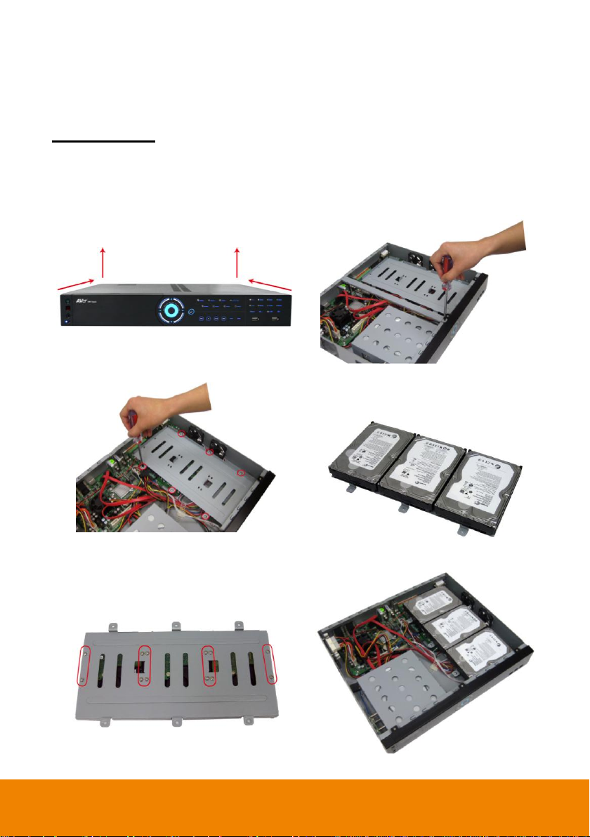
1. Loosen all screws (2 sides and back) and
Push the cover backward and lift to open the
case cover.
2. Loosen the screws of holder to make hard
disk install more easily.
3. Loosen all the screws of hard disk plate.
4. The hard disk plate can be installed 3 hard
disks. User can choose the position and
place the hard disk on it.
5. Turn the plate and hard disk over carefully
and secure the hard disk on the plate. If
hard disk cannot be fit to the screw hole,
then, you may adjust the hard disk position
to fit the screw hole.
6. Screw the plate within hard disk inside the
DVR unit.
II. Hardware Installation
Install the Hard Disk
IWH3216 Touch
The DVR unit can support up to 3 SATA hard disks. The hard disk installation steps are same for
IWH3216 Touch. Follow the illustrated instructions below to install the hard disk:
2
Page 5
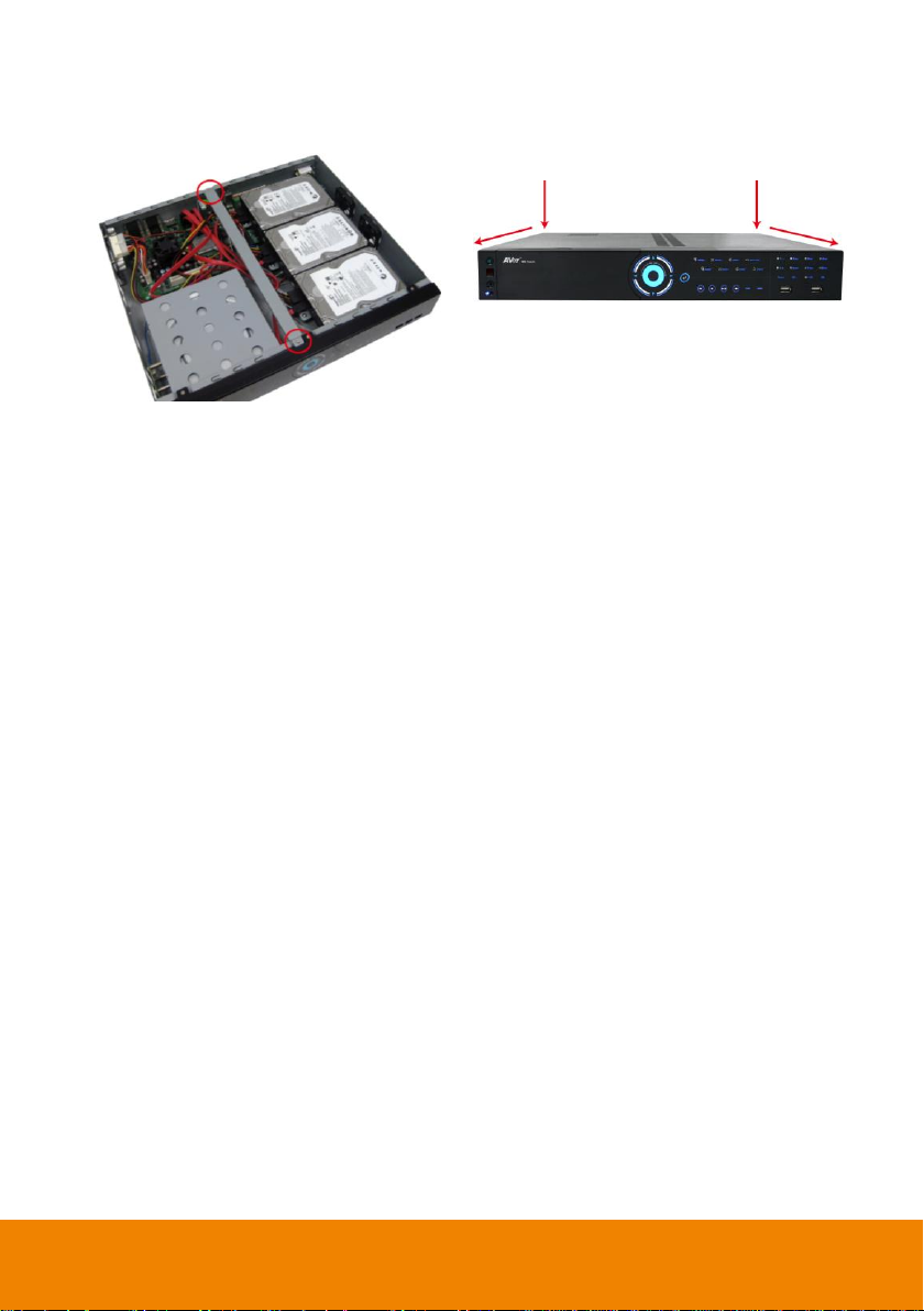
7. Screw the holder.
8. Push the cover forward and secure the
cover.
9. User may now connect all the cables and power on the DVR unit.
3
Page 6
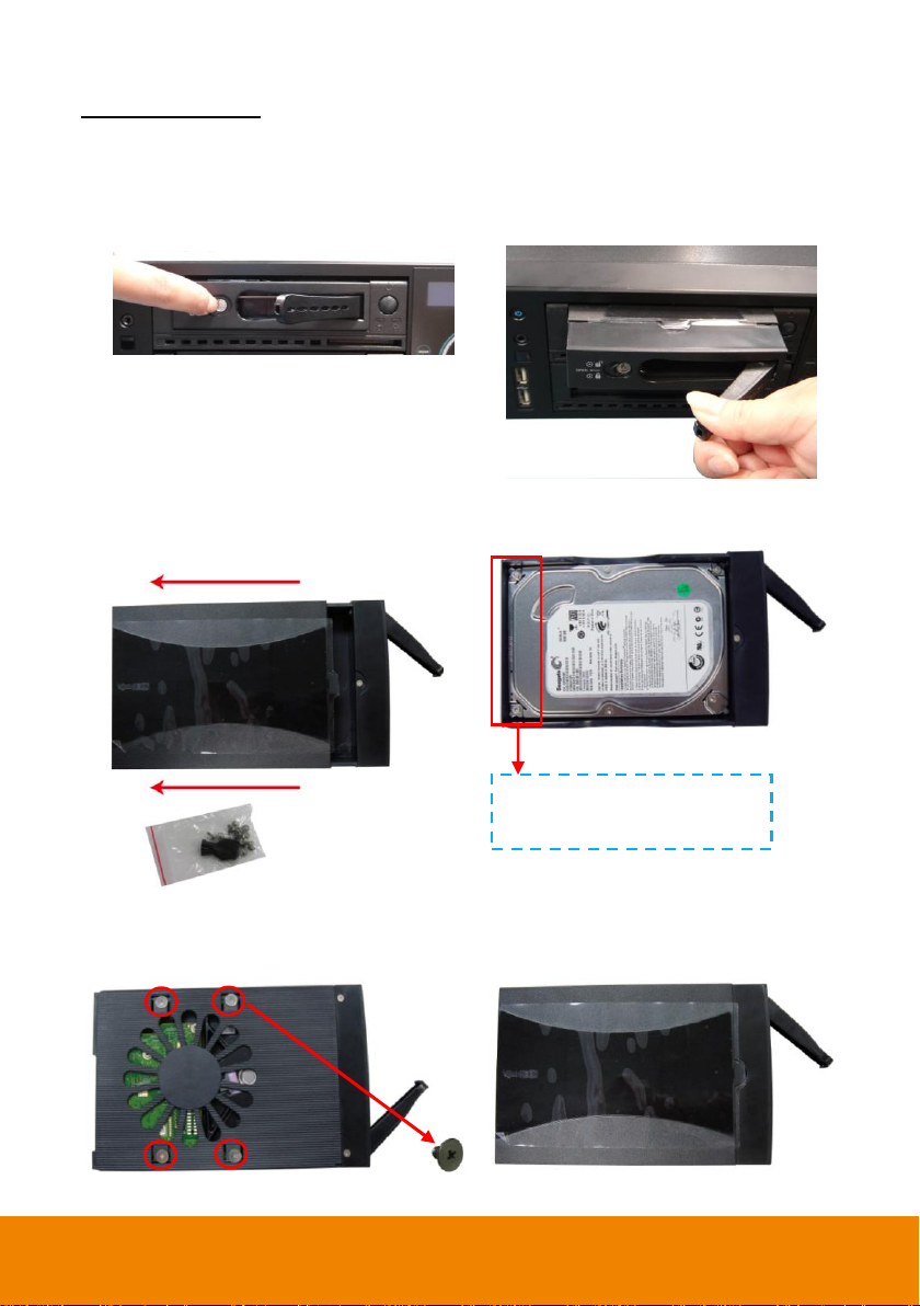
1. Push the lock to open the HDD drawer.
2. And then, pull out the HDD drawer from
DVR unit.
3. Open the HDD drawer case cover and
takes out the accessories kit (key &
screws).
Accessories kit
4. And then, place the SATA hard disk inside
the HDD drawer.
5. Turn the plate and hard disk over carefully
and secure the hard disk inside the HDD
drawer. Use the screw has flat head.
6. After screwed hard disk, turn the HDD
drawer over and close the case cover.
The hard disk’s connect interface
should be placed in this side of
HDD drawer.
IWH3216 Touch II
The DVR unit can support up to 4 SATA hard disks. Follow the illustrated instructions below to install
the hard disk:
4
Page 7
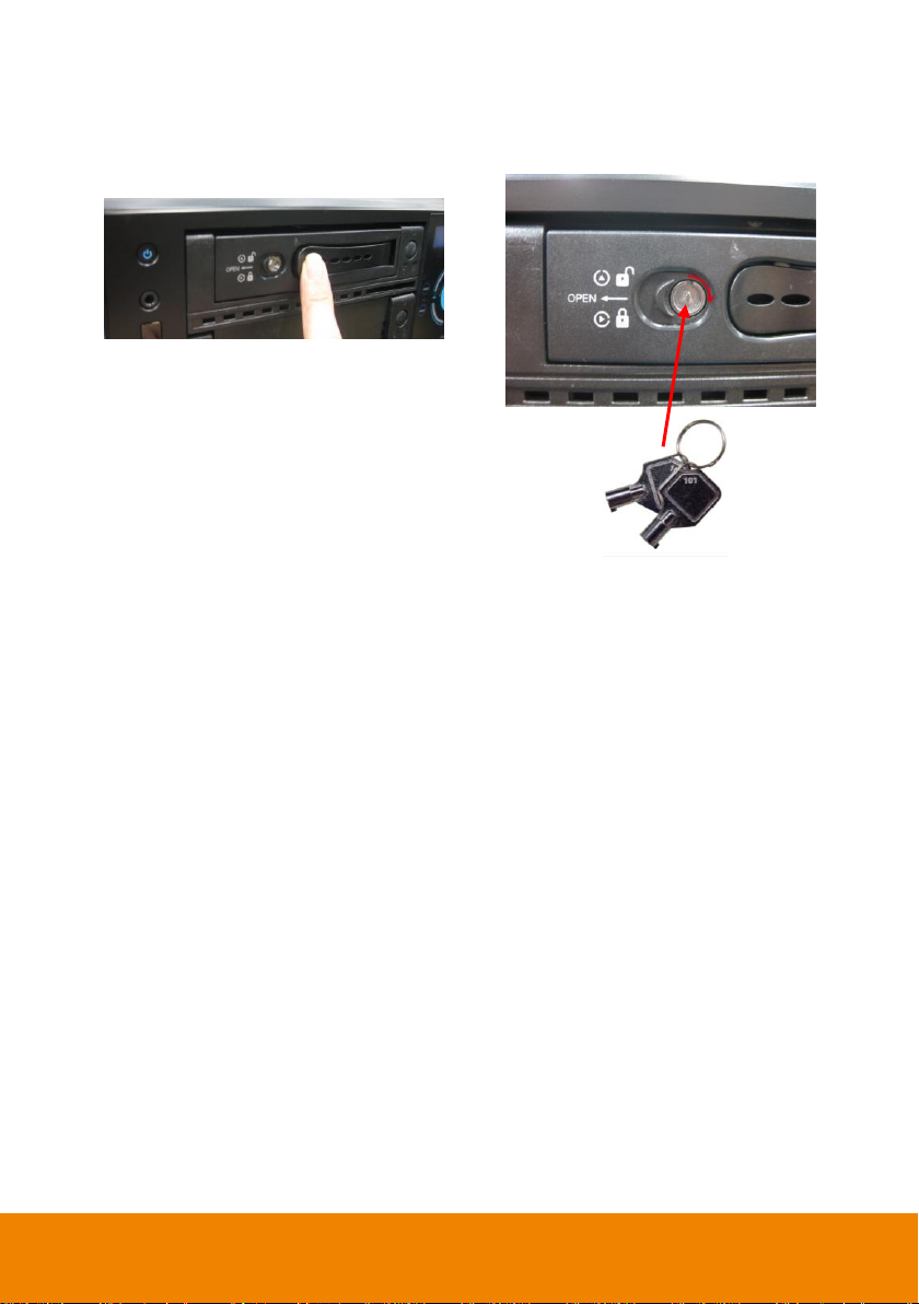
7. Slide the HDD drawer back to the DVR
unit.
8. Lock the HDD drawer by using the key that
is included in accessories kit.
9. User may now connect all the cables and power on the DVR unit.
5
Page 8

RS485 cable site
(Color of cable)
PTZ camera site
4
Red
RX+
5
Green
RX- 8 White
TX+ 9 Black
TX-
Connecting Devices
RS-485 cable definition
IWH3216 Touch
The back panel of the DVR unit, user can connect up to 16 cameras of analog camera. The DVR
unit also can connect 16 sensor devices, 4 alarm devices, and output video to 2 CRT/LCD monitor.
Follow the illustration below to make the connection:
For backup recorded video, plugging the pen drive or external hard disk through USB port, and then,
use the bundled software enables user to transfer, playback and segment the video.
6
Page 9

IWH3216 Touch II
The back panel of the DVR unit, user can connect up to 16 cameras of analog camera. The DVR
unit also can connect 16 sensor devices, 4 alarm devices, and output video to 2 CRT/LCD monitor.
Follow the illustration below to make the connection:
For backup recorded video, plugging the pen drive or external hard disk through USB port, and then,
use the bundled software enables user to transfer, playback and segment the video.
7
Page 10

Click to select
the channel
III. Operating the DVR System
Running the Unit for the First Time
When the unit is turned on for the first time, the system will prompt you to enter the CD-Key. After
enter the CD-Key, the DVR will enter Preview Mode interface.
To Connect the Camera
Before to monitor, user needs to connect the camera to get the live video. Please follow the below
steps to connect the camera.
Analog Camera
1. Plug the video cable to video connector of the DVR unit (for IWH3216 Touch only).
2. Connect video cable of camera to DVR unit (BNC port or connector of video cable). The video
will display on the channel that camera is connected.
IP Camera
1. In Preview mode, click Setup button (
2. In Camera setting window, select the channel that camera will be connected.
3. And then, select the IP Camera as Input.
and select Camera.
)
4. The IP camera detail window will show up. Select the way to connect the IP camera – Protocol
or URL. And then, enter or select all required data. Using Search Devices button can help user
to find all available IP cameras on your local network. If camera require authentication for
accessing, mark Authentication check box and enter the ID and Password of IP camera.
8
Page 11

5. After enter all required data, click Connect to make a connection with IP camera.
6. After connection successful, the video of camera should be display on the channel that camera
is connected.
Recording the Live Video
While monitoring, user can click Record ( ) button to save the live video on hard disk and
recorded video can playback in local site and remote site.
Preview mode
9
Page 12

Playback Recorded Video
1. Clicking Playback button.
.
2. Select the date and time to playback. The numbers from 00 to 23 represent the time in 24-hour
clock. The numbers from 01 to 16 represent the camera ID. The blue colored column indicates
that there is a recorded video file on that period of time. While the red colored column indicates
on where to start playing the recorded video file.
3. After selected the date and time, click OK to start playback. User will see the selected video file
playback on the screen.
Playback Mode
10
Page 13

Function buttons in Preview Mode
Name
Function
(1) Exit
Call up the Logout dialog box.
In the logout dialog box, you may do the following:
- Exit: To close the DVR program.
- Login: To sign-in in different account. Default user ID is admin and
password is admin.
- Compact: To switch to compact mode
- Guest: To switch to the guest mode. In guest mode, the functions are
limited to preview and playback function only. For complete functions
of DVR, please login as an administrator.
- Cancel: To exit Logout dialog box
- About: To update patch or find about the software info.
11
Page 14

Name
Function
(2) Split Screen
Mode
It provides 6 kinds of split display modes for your selection. You can
select one of the split display modes by clicking the icon.
i
- If there are only 4 cameras enabled, you won’t be able to switch to 9, 13 and, 16 split
screen mode.
- The DVR system will save the current operating mode (split screen mode, auto scan,
and compact mode status) when shutdown DVR application and apply the mode for
next login.
- When you are in single screen mode, Right click and Drag a square on the area you
want to enlarge.
- When you are in multiple-screen mode, Right click the video screen of the camera
and Drag on where you want to relocate it. To only display one of the video in the
multiple-screen mode, Left click on the video screen you only want to display.
(3) Status Bar
It shows the current time, system temperature, and the hard disk’s free
space.
(4) Record
To start recording. The button turns violet when it is recording. Click it
again and enter the password to stop.
(5) E-Map
To load up to 8 desired E-Maps in BMP or JPG image format, and locate
cameras, sensors, and relays to desired positions.
(6) Network
To allow inbound connections. When this function is enabled, the button
turns violet. Click it again to disable all inbound connections.
(7) Setup
When setting up the system for the first time, type the word “admin” in
the Password text box to access.
Click Setup ( ) button to configure settings for cameras, recording,
network, scheduler, backup, sensors, relays, alarms and user
authentication.
(8) PTZ
To call out a PTZ setup dialog to configure an appointed PTZ camera.
(9) Preview
Switch to Preview/Advanced mode. This allows you to view live camera
display. Press ctrl + F can freeze the live preview video screen. And
then, click Snapshot can save the freeze video screen.
(10) Playback
Switch to Playback mode. This allows you to view the recorded video file.
12
Page 15

Name
Function
(11) Camera Group
Tree
To view the user defined channel group tree. Click + of group to extend
group and drag the camera to surveillance screen to view. Click + of
camera to view the camera information.
(12) Camera ID
Click a desired icon to play the desired channel. After you click the icon, it
turns yellow. If you assign a split display mode and appoint a camera
number, the icon group of the cameras will turn yellow altogether.
(13) iPOSLive
To view the real time iPOS data of channels. Click the iPOSLive to call
out the real time iPOS data windows.
User can move the each channel of iPOS windows apart to proper
position. If user didn’t enable the multi-channel of iPOSLive, and then,
user only can view one channel each time.
13
Page 16

Name
Function
(13) iPOSLive
To switch to different channel, click Select Camera drop down list to
select the channel. To tempore stop iPOS data coming, click Freeze. To
un-freeze, click Transcation.
(14) Snapshot
Catch a static recording image and save it as a BMP or a JPG file.
(15) Event log
Click it to pop-up the Event Log Viewer dialog to check Event, Operation,
POS (Point of Sales), System and Network logs. You can select a
desired date and a log item to show all logs data in the table.
(16) AutoScan
Click it to start Auto Scan.
(17) Full screen
Use the entire area of the screen to only display the video. To return,
press the right button of the mouse or ESC on the keyboard or click the
arrow icon.
When you switch to full screen in multiple-screen mode, Left click to
toggle to only display one of the video in the multiple-screen mode or all.
(18) Alarm
Click Alarm status ( ) button to view the status or advanced
alarm information.
14
Page 17

Name
Function
(19) Live Playback
button
Click to playback the recorded file instantly in preview mode. When
the channel is in live playback mode, the icon is . Move the mouse to
the bottom of the live playback channel, the playback tool bar
( ) will show up.
Using the playback tool bar to control the playback. Total 4 channels can
be live playback at the same time.
(20) Volume
Adjust the audio volume of channel to a proper volume.
(21) On Screen
Keyboard
If the keyboard is not available, you may use the Virtual Keyboard.
15
Page 18

Name
Function
(1) Split Screen
Mode
Select from 6 kinds of split screen type to playback the recorded video
file of all the camera, or one camera over the other or alongside on a
single screen.
i
If there are only 4 cameras, you won’t be able to switch to 9, 13, and 16 split screen
mode.
To zoom in an area on the screen, Right click and Drag a square on the area you want to
enlarge.
(2) Progress bar
Show the progress of the file being played. You may move the bar to
seek at any location of the track.
(3) Hour Buttons
Select and click to playback the recorded video file on the specific time
frame.
i
The Hour buttons represent the time in 24-hour clock. The blue bar on top of the hour
button indicates that there is a recorded video file on that period of time. While the red bar
indicates that you are currently viewing the recorded video file.
Function Buttons in Playback Mode
To switch in Playback mode, click Playback button at the lower right corner of Advanced/Preview
mode user interface
16
Page 19

Name
Function
(4) Playback Control
Buttons
Begin: Move at the beginning of the recorded video file.
Previous: Go back to the previous frame.
Slower: Play the recorded video file at the speed of 1/2x, 1/4x, or 1/8x,
1/16x, or 1/32x.
Rewind: Wind back the recorded video file.
Pause: Briefly stop playing the recorded video file.
Play: Play the recorded video file.
Faster: Play the recorded video file at the speed of 2x, 4x, 8x, 16x or
32x.
Next: Go to the next frame.
End: Go to the end of the recorded video file.
(5) Archive
Select the date on the calendar and the time from 00 to 23 to where to
start playing the recorded video file.
– OPEN FILE: user can open the recorded file from HDD
– Channel 01~ 16&Channel 17 ~ 32: Switch to different channel group
of playback calendar. If DVR system supports less than 16 channels
(include 16 channels), the channel group switching button is
non-functional.
– Day Light Saving: the playback calendar will show the available
video records during day light saving time period.
i
The numbers from 00 to 23 represent the time in 24-hour clock. The numbers from 01 to
16 represent the camera ID. The blue colored column indicates that there is a recorded
video file on that period of time. While the red colored column indicates on where to start
playing the recorded video file.
(6) Preview
Switch to preview mode.
(7) Playback
Switch to playback mode.
(8) Status bar
Display the recorded date, time and play speed.
17
Page 20

Name
Function
(9) Camera ID
Show the number of cameras that are being viewed. When you are in
single screen mode, click the camera ID number to switch and view
other camera.
(10) iPOS Serach
To find iPOS event by keyword or period.
POSDB Path: where the iPOS data located.
Start Time: select the search start time and date
End Time: select the search end time and date
Select Camera: select the camera for iPOS events search
– Keyword: enter a keyword to search iPOS event. Mark Match
whole words exactly to 100% match the keyword that user has
entered.
The search result will display in Search Result windows. User can click
specific iPOS event to view and the iPOS detail will display in Search
Receipt.
To save the search result, click Save button. Click Print button to print
the search result.
To save the selected iPOS search receipt, click Save. Click Print to
print the selected iPOS event’s detail.
18
Page 21

Name
Function
(11) Export
Export includes Snapshot, Print, Output Video Clip, and Backup
function.
- Snapshot: Capture and save the screen shot either in *.jpg or
*.bmp format.
- Print: Print the screen shot.
- Output Video Clip: Save the segmented file in *.mpg, *.avi, or *.dvr
format.
- Backup: Save the playback file to USB device or DVD-ROM disk.
(12) Segment
Keep a portion of the recorded video.
1. Use the Playback Control buttons or drag the bar on the playback
progress bar and pause on where you want to start the cut. Then,
click Segment to set the begin mark.
2. Use the Playback Control buttons or drag the bar on the playback
progress bar and pause on where you want to end the cut. Then,
click Segment to set the end mark. To cancel segmentation or set
the segment marks from the start, click Segment button again.
3. Click Export → Output Video Clip button to save the wanted clip.
4. In the Save As dialog box, locate on where you want to save the file
or choose to Burn the video segment to CD/DVD ROM (only
for .*mpeg file format).
5. Select the file type and select the camera information display
position when playback. The camera information will be the
information of server name that user has defined in Network Setting.
6. If the select the file type is *.avi, user can mark Included audio to
include audio in output video segment.
7. To adjust Video Quality if needed.
8. Click Save to save the video segment.
19
Page 22

Name
Function
(13) Full screen
Use the entire area of the screen to only display the video. To return,
press the right button of the mouse or ESC on the keyboard or click the
arrow icon.
When you switch to full screen in multiple-screen mode, Left click to
toggle to only display one of the video in the multiple-screen mode or all.
(14) Event log
Show the record of activities that take place in the system. To filter the
records, select and click the option button to only display Event,
System, Operation, Network or POS.
(15) Bookmark
Mark a reference point when previewing the recorded video file to which
you may return for later reference. You may also set it to protect the file.
(16) Visual Search
Search from a specific camera by Date, Hour, Minute, 10 Seconds and
Second.
(17) Find Next
Search for the next event or changes in the motion detector frame. You
can use this when you are using Intelligent Search or Event Search
function.
(18) Event Search
Search from the recorded activities that take place in the system (i.e.,
Sensor, Motion, Video Loss, POS).
(19) Intelligent
Search
Search the changes in the motion detector frame.
(20) Audio
Enable/disable audio sound.
(21) De-interlace
To enhance the video quality. Set the de-interlace mode to #1, if you are
capturing motionless picture and #2, if it captures lots of movement.
Click to exit from
full screen mode
20
 Loading...