

Page 1
AVer Box type Camera
Installation Guide
Page 2

Table of Contents
IMPORTANT SAFEGUARD ................................................................................................. 1
PACKAGE CONTENTS ....................................................................................................... 2
OPTIONAL ACCESSORIES ................................................................................................ 2
BOX IP CAMERA PARTS .................................................................................................... 3
FRONT PANEL .................................................................................................................... 3
REAR PANEL ...................................................................................................................... 3
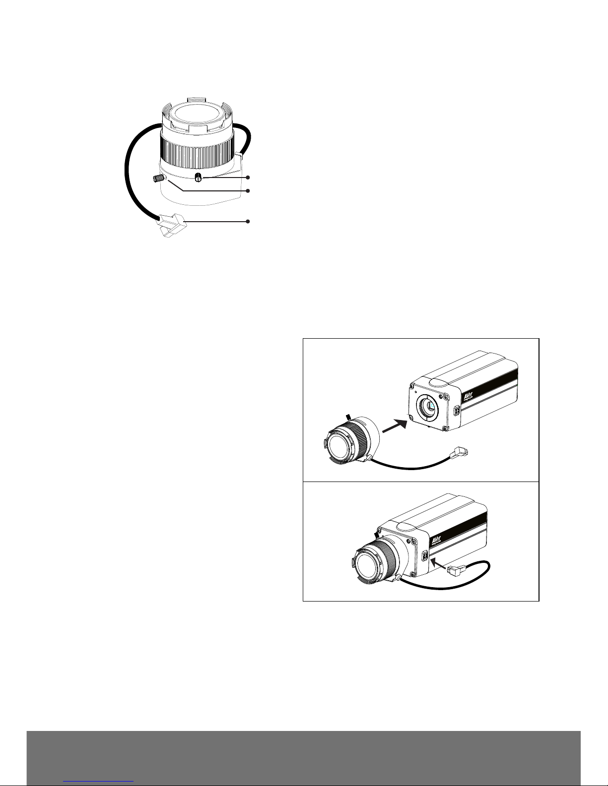
CS-MOUNT LENS ............................................................................................................... 4
IP CAMERA INSTALLATION ............................................................................................... 4
CONNECTING THE LENS....................................................................................................... 4
DEPLOYING NETWORK ........................................................................................................ 5
Network Connection via Ethernet Switch .................................................................... 5
Connect the power adapter to DC12V port of camera ................................................ 5
Power over Ethernet Connection ................................................................................ 6
RJ45 LED ........................................................................................................................ 6
CONNECTING EXTERNAL DEVICES TO I/O TERMINAL BLOCK .................................................... 7
POWER LED ...................................................................................................................... 7
INTERNAL CONNECTION DIAGRAM OF DI/DO ......................................................................... 7
ADJUSTING THE CS-MOUNT RING ......................................................................................... 8
FOCUSING THE IP CAMERA WITH BNC MONITOR ................................................................. 10
TECHNICAL SPECIFICATIONS .............................................................................................. 11
FX2000 (E)/FX3000-R (E) ........................................................................... 11
FCC NOTICE (CLASS B) .................................................................................................. 15
NOTICE .............................................................................................................................. 15
WARNING ................................ ................................................................ .......................... 15
GOVERNING LAW AND YOUR RIGHTS .......................................................................... 17
Page 3
1
ENGLISH
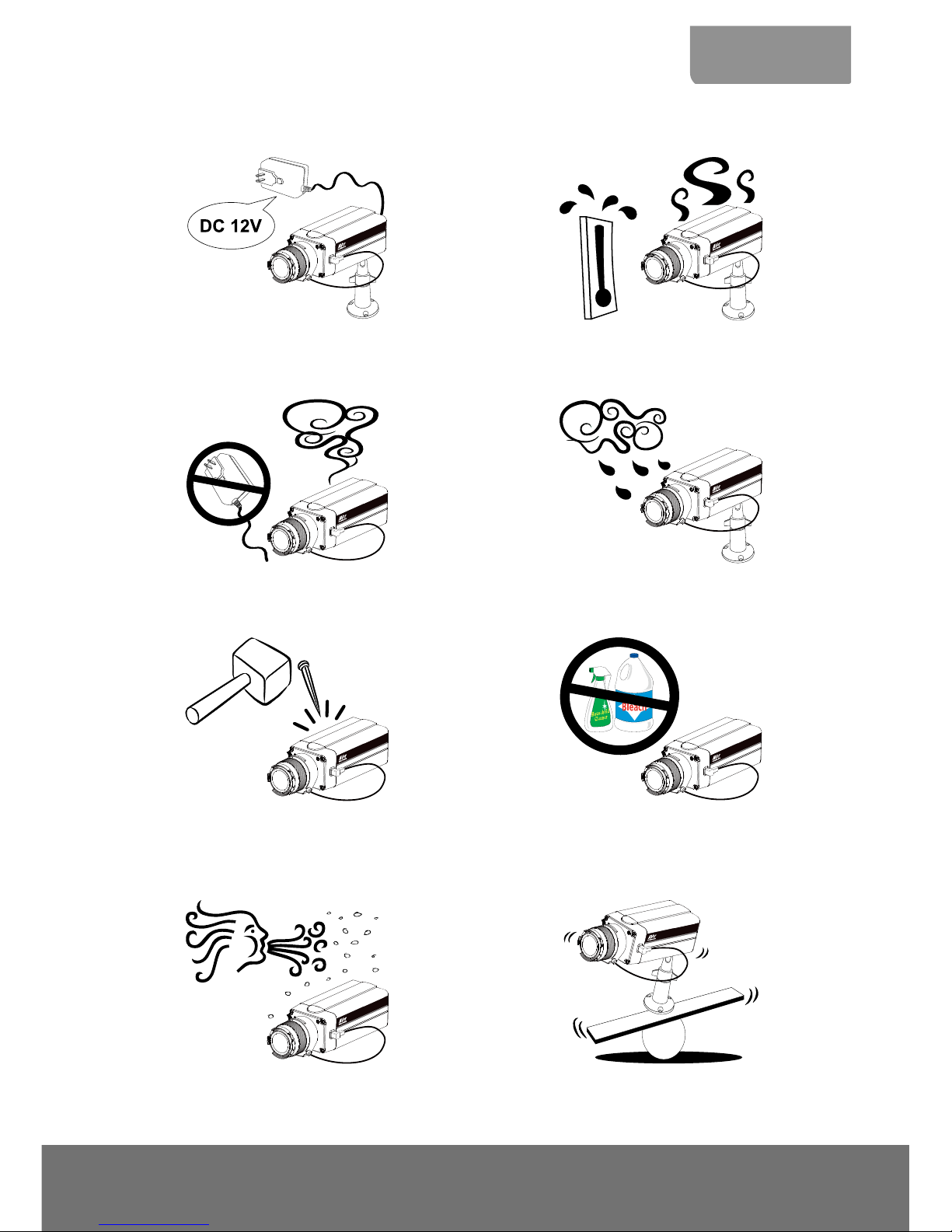
Important Safeguard
Do not use power supply with different voltage
other than DC 12V / PoE.
Keep this unit away from direct heat or sunlight.
Unplug the power of this unit as soon as smoke
or unusual odor is detected.
Do not expose this unit to rain or high humidity
environment.
Do not attempt to service this unit by yourself.
Always refer all servicing to qualified service
personnel.
Unplug the power supply before cleaning. Use
only a lens cleaning cloth and never use
benzine, thinner, or other solvent for cleaning.
Keep the IP camera housing close and prevent
the dust from getting in the housing.
Do not place the unit in unsteady surface and
also do not drop the unit.
Page 4
2
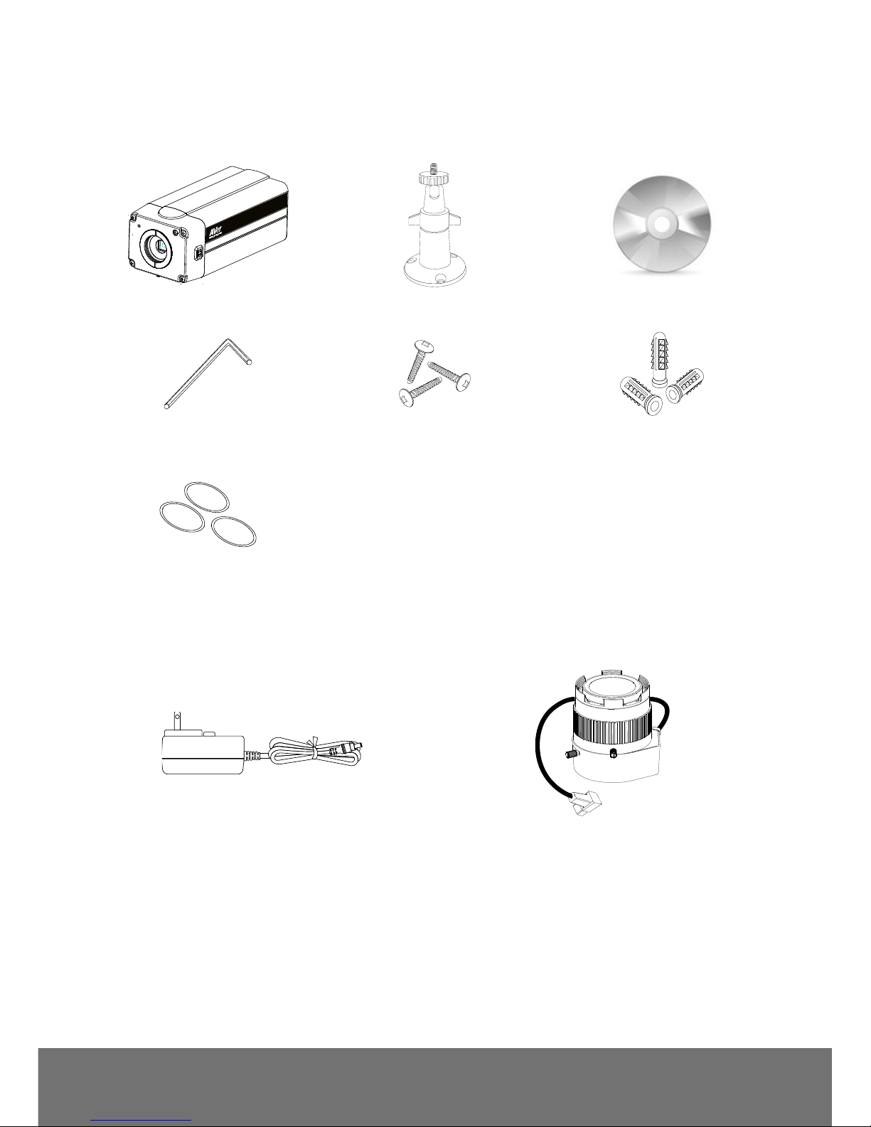
Package Contents
The following items are included in the package.
AVer Box type Camera
Camera stand
Software & Manual CD
L-type Hex Wrench
3 Screws
3 Plastic Anchors
3 Lens Ring Pad
Optional Accessories
Power Adapter (12V, 2A)
CS-mount Lens
* The power adapter will vary depending on the
standard power outlet of the country where it is
sold. Depending on your package the power
adapter maybe included.
Page 5
3
ENGLISH
BOX IP Camera Parts
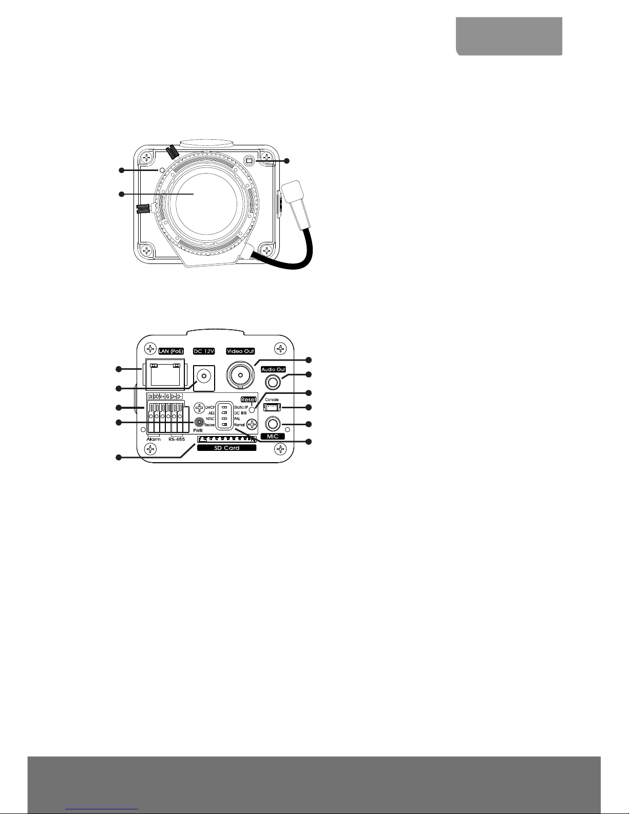
Front Panel
(1)
(2)
(3)
(1) Built-in MIC
(2) Lens
(3) Light Sensor
Rear Panel
(5)
(3)
(1)
(2)
(6)
(10)
(11)
(9)
(7)
(4)
(8)
(1) RJ45 Ethernet Port
(2) DC 12V
(3) I/O Terminal Block
(4) Power LED Indicator
(5) SD card slot
(6) Video Out
(7) Audio Out
(8) Reset button
(9) Console
(10) MIC
(11) DIP switch
DHCP/Static: Switch IP mode
to DHCP (dynamic IP) or
Static (fixed IP) mode.
AES/DC IRIS: Select AES
(automatic shutter) or DC
IRIS.
NTSC/PAL: Set to NTSC or
PAL mode.
Rescue/Normal: N/A
[Note] The reset button will set all the configuration settings back to factory default.
Page 6
4
CS-Mount Lens
(1)
(3)
(2)
(1) Zoom controller
(2) Focus controller
(3) DC-Iris control cable
IP Camera Installation
This section provides useful tips on how to adjust the IP camera to meet your needs.
Connecting the Lens
1. Screw in the CS-mount lens clockwise to
the CS-mounting ring. Make sure the lens
adhesive cover is removed when using it for
the first time.
2. Connect the CS-mount lens cable to the
socket.
Page 7

5
ENGLISH
Deploying Network
Network Connection via Ethernet Switch
Connect the RJ45 cable from the Ethernet switch to RJ45 Ethernet jack of camera
Ethernet Switch
Connect the power adapter to DC12V port of camera
Power Adapter
Wall Outlet
Page 8

6
Power over Ethernet Connection
Box type camera is fully complied with PoE standard. It allows you to use PoE enabled switch or PoE
injector to transmit data and power thru single Ethernet cable.
PoE Enabled Switch Connection Diagram
PoE Switch
PoE Injector Connection Diagram
Ethernet Switch
PoE Injector
Power cable
Wall outlet
RJ45 LED
LED
Status
Blinking Green
Connected to 100 Base-T mode and also transmitting and receiving data.
Steady Yellow
Connected to the Internet.
Page 9

7
ENGLISH
Connecting External Devices to I/O Terminal Block
(5)
(1)
(2)
(3)
(4)
(6)
(1) Alarm Data In
(2) Alarm Data Out
(3) Power 12V support 200mA
(4) Ground
(5) RS-485 (+)
(6) RS-485 (-)
Power LED
LED
Status
Steady Red
Power on
Blinking Red
Firmware update complete
No Light
Power off
Internal Connection Diagram of DI/DO
Page 10

8
Adjusting the CS-mount Ring
1. Unplug the CS-mount lens cable from the
socket.
2. Unscrew the CS-mount lens
counterclockwise.
3. Place one lens ring pad.
4. Screw the CS-mount lens and connect the
CS-mount lens cable to the socket. Check if
the IP camera can display proper image. If
not, repeat step 3 and 4 to add the next ring.
If all the rings are used up and still the IP
camera cannot display proper image.
Remove all the rings and continue to next
step.
5. Using the L-type hex wrench loosen the bolt
underneath the IP camera.
Page 11

9
ENGLISH
6. Remove the CS-mount ring from the IP
camera.
7. Screw the CS-mount ring to the CS-mount
lens.
8. Screw the CS-mount lens clockwise back.
Unscrew a little and plug the CS-mount lens
cable to the socket. Repeat this till the IP
camera display the image properly.
9. Once the IP camera has detected the image,
use the L-type hex wrench slightly secure bolt
underneath the IP camera.
[Note] Do not fully tighten bolt underneath the IP
camera for it may damage the CS-mount ring.
Page 12

10
Focusing the IP Camera with BNC Monitor
The IP camera is supported with BNC analog video out port which allows you to connect an analog
display devices such as an LCD BNC monitor for you to adjust the camera focus and zoom.
1. Connect the LCD BNC monitor to the Video Out port of IP camera using a BNC cable.
LCD BNC Monitor
2. Loosen up the focus and zoom control screws and adjust the focus and zoom range. Tighten the
focus and zoom screw once you are done adjusting.
Page 13

11
ENGLISH
Technical Specifications
FX2000 (E)/FX3000-R (E)
Model
FX2000 (E)
FX3000-R (E)
Len spec.
Computer AG3Z3112FCS-MPIR (Optional)
lens type
vari-focal Lens (CS mount)
F/no
F/1.2
Iris type
DC-Iris
focal length
f3.1~8mm
View Angle
H 99°(W)~42.8°(T)
V 52.7°(W)~23.2(T)
H 93.6°(W)~34.4°(T)
V 63.4°(W)~24.2(T)
MFZ Support
N/A
Camera image
Min. illumination
0.15 Lux@F/1.2 in day mode
(color)
0.001 Lux@F/1.2 in night mode
(B/W)
0.15 Lux@F/1.2 in day mode
(color)
0.0015 Lux@F/1.2 in night mode
(B/W)
Built-in LED
No
IR distance
No
Built-in mechanical ICR
Yes
Auto IRIS
Yes
Video
Compression
H.264/MPEG-4/MJPEG
Max. resolution
1920 x 1080
2048 x 1536
Frame rate
1920 x 1080 @ 30fps
2048 x 1536 @ 20fps
(Wide Angle)
1920 x 1080 @ 30fps (Normal
mode)
H.264/MPEG-4
bit rate mode
VBR, 5 levels
CBR, 64/128/512/768Kbps & 1/2/3/4/6/8/10/12Mbps
MJPEG quality
5 levels
Regional of Interest
Yes
Page 14

12
Model
FX2000 (E)
FX3000-R (E)
Video
Smart Stream
Yes, 5 windows
Image orientation
mirror, flip
Motion Detection zones
3
Privacy mask areas
3
BLC
Yes
D-WDR
Yes
No
Sensor-WDR
No
Yes
De-noise
2D/3D
Day & night function
Auto/Manual/Schedule
ePTZ
Yes
Corridor Mode
Yes
Cross Detection
Yes
Audio
Encoder
G.711 (μ-law)/G.726 (bit rate 16K~64bps) /AAC
audio compression
Streaming
2-ways audio
Microphone
External microphone input
Network
Protocols
TCP/IP (IPv4/IPv6), HTTP, HTTPS, UPnP, SMTP, FTP, DHCP, NTP,
DDNS, PPPoE, Samba, QoS, SNMP(V1/V2c/V3), 802.1X
Ethernet
10/100 Base-T, RJ45 connector
ONVIF
V2.X (Profile S), conformance test V12.06
Security
Password protection/IP Filter
Users
up to 10 users simultaneously
Page 15

13
ENGLISH
Model
FX2000 (E)
FX3000-R (E)
Event
Profiles
32 sets
Triggers
Alarm Interval, Motion Detection Region, Digital Input, SD Card,
Network
Actions
Trigger: Digital Output, Alarm Audio
Send out video clip: FTP, NAS, SD card
Send out snapshot / log: FTP, NAS, SD card, mail
Interface
Digital input/output
1/1
BNC Video output
Yes
Built-in storage option
SDHC & SDXC card (64GB max.)
Built-in micophone
Yes
External microphone input
Yes
External Audio output
Yes
RS-485
Yes
General
Power supply
DC 12V(2A)/PoE
Power consumption
DC: 5.0W (TYP)
POE: 6.5W (TYP)
PoE
PoE Class 3 (IEEE802.3af)
Dimensions
165.05mm x 58.6mm x 69mm (L x H x W)
Net weight
490g (w/o bracket)
Temperature and humidity
0°C~50°C, 20%~90%
Software Requirement
OS
Windows® XP/7/8
Browser
IE 8/9/10/11 (Full Function), Chrome
Firefox and Safari (Basic Function)
Firmware remote upgrade
Yes (via HTTP)
Page 16

14
Model
FX2000 (E)
FX3000-R (E)
Bundled Software
ExpressGO
free up to 32CH
IPCAM Utility
Yes
SecureCenter
Yes
Warranty
Main body
2 years
Accessories
1 year
Page 17

15
FCC NOTICE (Class B)
This device complies with Part 15 of the FCC Rules. Operation is subject to the following
two conditions: (1) this device may not cause harmful interference, and (2) this device
must accept any interference received, including interference that may cause undesired
operation.
Federal Communications Commission Statement
NOTE- This equipment has been tested and found to comply with the limits for a Class B digital device,
pursuant to Part 15 of the FCC Rules. These limits are designed to provide reasonable protection
against harmful interference in a residential installation. This equipment generates uses and can
radiate radio frequency energy and, if not installed and used in accordance with the instructions, may
cause harmful interference to radio communications. However, there is no guarantee that interference
will not occur in a particular installation. If this equipment does cause harmful interference to radio or
television reception, which can be determined by tuning the equipment off and on, the user is
encouraged to try to correct the interference by one or more of the following measures:
Reorient or relocate the receiving antenna.
Increase the separation between the equipment and receiver.
Connect the equipment into an outlet on a circuit different from that to which the receiver is
connected.
Consult the dealer or an experienced radio/television technician for help.
European Community Compliance Statement (Class B)
This product is herewith confirmed to comply with the requirements set out in the Council
Directives on the Approximation of the laws of the Member States relating to
Electromagnetic Compatibility Directive 2004/108/EC
COPYRIGHT
© 2014 AVer Information Inc. All rights reserved.
All rights of this object belong to AVer Information Inc. Reproduced or transmitted in any form
or by any means without the prior written permission of AVer Information Inc. is prohibited. All
information or specifications are subject to change without prior notice. “AVer” is a trademark
owned by AVer Information Inc. Other trademarks used herein for description purpose only
belong to each of their companies.
NOTICE
SPECIFICATIONS ARE SUBJECT TO CHANGE WITHOUT PRIOR NOTICE. THE
INFORMATION CONTAINED HEREIN IS TO BE CONSIDERED FOR REFERENCE ONLY.
WARNING
TO REDUCE RISK OF FIRE OR ELECTRIC SHOCK, DO NOT EXPOSE THIS APPLIANCE TO
RAIN OR MOISTURE. WARRANTY VOID FOR ANY UNAUTHORIZED PRODUCT
MODIFICATION.
THE MARK OF CROSSED-OUT WHEELED BIN INDICATES THAT THIS
PRODUCT MUST NOT BE DISPOSED OF WITH YOUR OTHER HOUSEHOLD
WASTE. INSTEAD, YOU NEED TO DISPOSE OF THE WASTE EQUIPMENT BY
HANDING IT OVER TO A DESIGNATED COLLECTION POINT FOR THE
RECYCLING OF WASTE ELECTRICAL AND ELECTRONIC EQUIPMENT. FOR
MORE INFORMATION ABOUT WHERE TO DROP OFF YOUR WASTE
EQUIPMENT FOR RECYCLING, PLEASE CONTACT YOUR HOUSEHOLD
WASTE DISPOSAL SERVICE OR THE SHOP WHERE YOU PURCHASED THE
PRODUCT.
Page 18

16
Limited Warranty
AVer Information, Inc. (“AVer”) warrants that the applicable product (“Product”) substantially conforms
to AVer’s documentation for the product and that its manufacture and components are free of defects
in material and workmanship under normal use. “You” as used in this agreement means you
individually or the business entity on whose behalf you use or install the product, as applicable. This
limited warranty extends only to You as the original purchaser. Except for the foregoing, the Product is
provided “AS IS.” In no event does AVer warrant that You will be able to operate the Product without
problems or interruptions, or that the Product is suitable for your purposes. Your exclusive remedy
and the entire liability of AVer under this paragraph shall be, at AVer’s option, the repair or replacement
of the Product with the same or a comparable product. This warranty does not apply to (a) any Product
on which the serial number has been defaced, modified, or removed, or (b) cartons, cases, batteries,
cabinets, tapes, or accessories used with this product. This warranty does not apply to any Product
that has suffered damage, deterioration or malfunction due to (a) accident, abuse, misuse, neglect, fire,
water, lightning, or other acts of nature, commercial or industrial use, unauthorized product
modification or failure to follow instructions included with the Product, (b) misapplication of service by
someone other than the manufacturer’s representative, (c) any shipment damages (such claims must
be made with the carrier), or (d) any other causes that do not relate to a Product defect. The Warranty
Period of any repaired or replaced Product shall be the longer of (a) the original Warranty Period or (b)
thirty (30) days from the date of delivery of the repaired or replaced product.
Limitations of Warranty
AVer makes no warranties to any third party. You are responsible for all claims, damages, settlements,
expenses, and attorneys’ fees with respect to claims made against You as a result of Your use or
misuse of the Product. This warranty applies only if the Product is installed, operated, maintained, and
used in accordance with AVer specifications. Specifically, the warranties do not extend to any failure
caused by (i) accident, unusual physical, electrical, or electromagnetic stress, neglect or misuse, (ii)
fluctuations in electrical power beyond AVer specifications, (iii) use of the Product with any accessories
or options not furnished by AVer or its authorized agents, or (iv) installation, alteration, or repair of the
Product by anyone other than AVer or its authorized agents.
Disclaimer of Warranty
EXCEPT AS EXPRESSLY PROVIDED OTHERWISE HEREIN AND TO THE MAXIMUM EXTENT
PERMITTED BY APPLICABLE LAW, AVER DISCLAIMS ALL OTHER WARRANTIES WITH
RESPECT TO THE PRODUCT, WHETHER EXPRESS, IMPLIED, STATUTORY OR OTHERWISE,
INCLUDING WITHOUT LIMITATION, SATISFACTORY QUALITY, COURSE OF DEALING, TRADE
USAGE OR PRACTICE OR THE IMPLIED WARRANTIES OF MERCHANTABILITY, FITNESS FOR A
PARTICULAR PURPOSE OR NONINFRINGEMENT OF THIRD PARTY RIGHTS.
Limitation of Liability
IN NO EVENT SHALL AVER BE LIABLE FOR INDIRECT, INCIDENTAL, SPECIAL, EXEMPLARY,
PUNITIVE, OR CONSEQUENTIAL DAMAGES OF ANY NATURE INCLUDING, BUT NOT LIMITED
TO, LOSS OF PROFITS, DATA, REVENUE, PRODUCTION, OR USE, BUSINESS INTERRUPTION,
OR PROCUREMENT OF SUBSTITUTE GOODS OR SERVICES ARISING OUT OF OR IN
CONNECTION WITH THIS LIMITED WARRANTY, OR THE USE OR PERFORMANCE OF ANY
PRODUCT, WHETHER BASED ON CONTRACT OR TORT, INCLUDING NEGLIGENCE, OR ANY
OTHER LEGAL THEORY, EVEN IF AVER HAS ADVISED OF THE POSSIBILITY OF SUCH
DAMAGES. AVER’S TOTAL, AGGREGATE LIABILITY FOR DAMAGES OF ANY NATURE,
REGARDLESS OF FORM OF ACTION, SHALL IN NO EVENT EXCEED THE AMOUNT PAID BY
YOU TO AVER FOR THE SPECIFIC PRODUCT UPON WHICH LIABILITY IS BASED.
Page 19

17
Governing Law and Your Rights
This warranty gives you specific legal rights; You may also have other rights granted under state law.
These rights vary from state to state.
 Loading...