

Avaya Secure Router 4134, Secure Router 2330 Hardware Installation

Installation — Hardware Components
Avaya Secure Router 2330/4134
Release 10.3.5
NN47263-301
Issue 04.02
August 2013

©
2013 Avaya Inc.
All Rights Reserved.
Notice
While reasonable efforts have been made to ensure that the
information in this document is complete and accurate at the time of
printing,
right to make changes and corrections to the information in this
document without the obligation to notify any person or organization of
such changes.
Documentation disclaimer
“Documentation” means information published by Avaya in varying
mediums which may include product information, operating instructions
and performance specifications that Avaya generally makes available
to users of its products. Documentation does not include marketing
materials. Avaya shall not be responsible for any modifications,
additions, or deletions to the original published version of
documentation unless such modifications, additions, or deletions were
performed by Avaya. End User agrees to indemnify and hold harmless
Avaya, Avaya's agents, servants and employees against all claims,
lawsuits, demands and judgments arising out of, or in connection with,
subsequent modifications, additions or deletions to this documentation,
to the extent made by End User.
Link disclaimer
Avaya is not responsible for the contents or reliability of any linked
websites referenced within this site or documentation provided by
Avaya. Avaya is not responsible for the accuracy of any information,
statement or content provided on these sites and does not necessarily
endorse the products, services, or information described or offered
within them. Avaya does not guarantee that these links will work all the
time and has no control over the availability of the linked pages.
Warranty
Avaya provides a limited warranty on its hardware and Software
(“Product(s)”). Refer to your sales agreement to establish the terms of
the limited warranty. In addition, Avaya’s standard warranty language,
as well as information regarding support for this Product while under
warranty is available to Avaya customers and other parties through the
Avaya Support website:
you
of the United States and Canada, the warranty is provided to you by
said Avaya reseller and not by Avaya. “Software” means computer
programs in object code, provided by Avaya or an Avaya Channel
Partner, whether as stand-alone products or pre-installed on hardware
products, and any upgrades, updates, bug fixes, or modified versions.
Licenses
THE SOFTWARE LICENSE TERMS AVAILABLE ON THE AVAYA
WEBSITE,
APPLICABLE TO ANYONE WHO DOWNLOADS, USES AND/OR
INSTALLS AVAYA SOFTWARE, PURCHASED FROM AVAYA INC.,
ANY AVAYA AFFILIATE, OR AN AUTHORIZED AVAYA RESELLER
(AS APPLICABLE) UNDER A COMMERCIAL AGREEMENT WITH
AVAYA OR AN AUTHORIZED AVAYA RESELLER. UNLESS
OTHERWISE AGREED TO BY AVAYA IN WRITING, AVAYA DOES
NOT
FROM ANYONE OTHER THAN AVAYA, AN AVAYA AFFILIATE OR
AN AVAYA AUTHORIZED RESELLER; AVAYA RESERVES THE
RIGHT TO TAKE LEGAL ACTION AGAINST YOU AND ANYONE
ELSE USING OR SELLING THE SOFTWARE WITHOUT A LICENSE.
BY INSTALLING, DOWNLOADING OR USING THE SOFTWARE, OR
AUTHORIZING OTHERS TO DO SO, YOU, ON BEHALF OF
YOURSELF AND THE ENTITY FOR WHOM YOU ARE INSTALLING,
DOWNLOADING OR USING THE SOFTWARE (HEREINAFTER
REFERRED TO INTERCHANGEABLY AS “YOU” AND “END USER”),
AGREE TO THESE TERMS AND CONDITIONS AND CREATE A
BINDING CONTRACT BETWEEN YOU AND AVAYA INC. OR THE
APPLICABLE AVAYA AFFILIATE (“AVAYA”).
Avaya assumes no liability for any errors. Avaya reserves the
http://support.avaya.com. Please note that if
acquired the Product(s) from an authorized Avaya reseller outside
HTTP://SUPPORT.AVAYA.COM/LICENSEINFO ARE
EXTEND THIS LICENSE IF THE SOFTWARE WAS OBTAINED
Copyright
Except where expressly stated otherwise, no use should be made of
materials on this site, the Documentation, Software, or hardware
provided
Product provided by Avaya including the selection, arrangement and
design of the content is owned either by Avaya or its licensors and is
protected by copyright and other intellectual property laws including the
sui generis rights relating to the protection of databases. You may not
modify, copy, reproduce, republish, upload, post, transmit or distribute
in any way any content, in whole or in part, including any code and
software unless expressly authorized by Avaya. Unauthorized
reproduction, transmission, dissemination, storage, and or use without
the express written consent of Avaya can be a criminal, as well as a
civil offense under the applicable law.
Third Party Components
“Third Party Components” mean certain software programs or portions
thereof included in the Software that may contain software (including
open source software) distributed under third party agreements (“Third
Party Components”), which contain terms regarding the rights to use
certain portions of the Software (“Third Party Terms”). Information
regarding distributed Linux OS source code (for those Products that
have distributed Linux OS source code) and identifying the copyright
holders of the Third Party Components and the Third Party Terms that
apply is available in the Documentation or on Avaya’s website at:
support.avaya.com/Copyright. You agree to the Third Party Terms for
any such Third Party Components.
Note to Service Provider
The Product may use Third Party Components that have Third Party
Terms that do not allow hosting and may need to be independently
licensed for such purpose.
Preventing Toll Fraud
“Toll Fraud” is the unauthorized use of your telecommunications
system by an unauthorized party (for example, a person who is not a
corporate employee, agent, subcontractor, or is not working on your
company's behalf). Be aware that there can be a risk of Toll Fraud
associated
in substantial additional charges for your telecommunications services.
Avaya Toll Fraud intervention
If you suspect that you are being victimized by Toll Fraud and you need
technical assistance or support, call Technical Service Center Toll
Fraud Intervention Hotline at +1-800-643-2353 for the United States
and Canada. For additional support telephone numbers, see the Avaya
Support website:
vulnerabilities with Avaya products should be reported to Avaya by
sending mail to: securityalerts@avaya.com.
Trademarks
The trademarks, logos and service marks (
site, the Documentation and Product(s) provided by Avaya are the
registered or unregistered Marks of Avaya, its affiliates, or other third
parties. Users are not permitted to use such Marks without prior written
consent from Avaya or such third party which may own the Mark.
Nothing contained in this site, the Documentation and Product(s)
should be construed as granting, by implication, estoppel, or otherwise,
any license or right in and to the Marks without the express written
permission of Avaya or the applicable third party.
Avaya is a registered trademark of Avaya Inc.
All non-Avaya trademarks are the property of their respective owners.
Linux® is the registered trademark of Linus Torvalds in the U.S. and
other countries.
Downloading Documentation
For the most current versions of Documentation, see the Avaya
Support website:
by Avaya. All content on this site, the documentation and the
http://
with your system and that, if Toll Fraud occurs, it can result
http://support.avaya.com. Suspected security
“Marks”) displayed in this
http://support.avaya.com.
2 Installation — Hardware Components August 2013
Comments? infodev@avaya.com

Contact Avaya Support
See the Avaya Support website: http://support.avaya.com for product
notices and articles, or to report a problem with your Avaya product.
For a list of support telephone numbers and contact addresses, go to
the Avaya Support website: http://support.avaya.com, scroll to the
bottom of the page, and select Contact Avaya Support.
Installation — Hardware Components August 2013 3

4 Installation — Hardware Components August 2013
Comments? infodev@avaya.com

Contents
Chapter 1: Avaya Secure Router 2330/4134 safety precautions....................................
Safety requirement for handling and installing modules...........................................................................
Types of notices...............................................................................................................................
Cautions and warnings for the Secure Router 2330/4134...............................................................
Foreign Exchange Station (FXS) Interface Modules........................................................................
Foreign Exchange Office (FXO) Interface Modules.........................................................................
Personal safety and equipment protection................................................................................................
Module protection.............................................................................................................................
Cables and connectors protection....................................................................................................
Electrostatic discharge.....................................................................................................................
Antistatic material.............................................................................................................................
Chapter 2: Introduction......................................................................................................
Purpose.....................................................................................................................................................
Related Resources....................................................................................................................................
Documentation.................................................................................................................................
Training............................................................................................................................................
Avaya Mentor videos........................................................................................................................
Support.............................................................................................................................................
Chapter 3: New in this release...........................................................................................
Chapter 4: Avaya Secure Router 2330/4134 hardware components fundamentals.....
Secure Router 4134 Power supply units...................................................................................................
Secure Router 4134 Fan tray....................................................................................................................
Interface modules for the Secure Router 2330/4134................................................................................
T1/E1 Small Module.........................................................................................................................
ISDN BRI S/T and ISDN BRI U Small Modules...............................................................................
Serial Small Module.........................................................................................................................
FXS Small Module............................................................................................................................
FXO Small Module...........................................................................................................................
T1/E1 Medium Module (supported on Secure Router 4134 only)....................................................
HSSI Medium Module (supported on Secure Router 4134 only).....................................................
CT3 Medium Module (supported on Secure Router 4134 only).......................................................
DS3 Medium Module (supported on Secure Router 4134 only).......................................................
GbE Medium Module (supported on Secure Router 4134 only)......................................................
FE and FE/PoE Medium Module (supported on Secure Router 4134 only).....................................
Mediation Server Module for OCS (supported on Secure Router 4134 only)..................................
Voice Carrier Medium Module (supported on Secure Router 4134 only).........................................
GbE Large Module (supported on Secure Router 4134 only)..........................................................
ADSL2+ Small Module.....................................................................................................................
Secure Router 4134 Internal hardware components................................................................................
DDR SO-DIMM.................................................................................................................................
VPN/IPSec module...........................................................................................................................
Internal PVM.....................................................................................................................................
Internal system compact flash..........................................................................................................
Hot swapping Secure Router 4134 hardware components......................................................................
9
9
9
10
11
12
12
12
13
13
13
15
15
15
15
15
15
16
17
19
19
21
22
23
25
27
30
32
34
35
36
37
38
40
41
43
43
45
47
48
48
49
50
51
Installation — Hardware Components August 2013 5

Compatible internal modules for Secure Router 2330..............................................................................
Replaceable parts for Secure Router 2330...............................................................................................
Chapter 5: Installing Avaya Secure Router 2330/4134 hardware components.............
Installing the interface modules................................................................................................................
Prerequisites....................................................................................................................................
Installing a Small Module.................................................................................................................
Installing a Medium Module on the Secure Router 4134.................................................................
Installing a Large Module on the Secure Router 4134.....................................................................
Installing a Small Module in the Secure Router 4134 Voice Carrier Medium Module......................
Hot swapping interface modules...............................................................................................................
Connecting Secure Router 2330/4134 power cables...............................................................................
Connecting AC power cables...........................................................................................................
Connecting DC power......................................................................................................................
Connecting the console port cable............................................................................................................
Installing or replacing a Secure Router 4134 power supply module.........................................................
Replacing a Secure Router 4134 fan tray module....................................................................................
Installing or removing the internal VPN/IPSec module on the Secure Router 4134.................................
Installing the internal VPN/IPSec module.........................................................................................
Removing the internal VPN/IPSec module.......................................................................................
Installing or removing an internal PVM on the Secure Router 4134.........................................................
Installing the internal PVM................................................................................................................
Removing the internal PVM..............................................................................................................
Replacing the DIMM in the Secure Router 4134......................................................................................
Installing or removing the DIMM on the Secure Router 4134 Mediation Server Module for OCS............
Installing a DIMM on the Mediation Server Module..........................................................................
Removing a DIMM from the Mediation Server Module....................................................................
Replacing the Secure Router 4134 internal Compact Flash.....................................................................
Removing the Secure Router 2330 top cover...........................................................................................
Installing or removing the internal SCIM module on the Secure Router 2330..........................................
Installing the internal SCIM module..................................................................................................
Removing the internal SCIM module................................................................................................
Installing or removing the internal PVIM module on the Secure Router 2330..........................................
Installing the internal PVIM module..................................................................................................
Removing the internal PVIM module................................................................................................
Replacing the Secure Router 2330 DIMM........................................................................................
Replacing the Secure Router 2330 internal Compact Flash............................................................
Environmental requirements.............................................................................................
Interface connector pin assignments...............................................................................
Serial cable descriptions....................................................................................................
DTE V.35 serial cable...............................................................................................................................
DCE V.35 serial cable...............................................................................................................................
DTE X.21 serial cable...............................................................................................................................
DCE X.21 serial cable...............................................................................................................................
DTE RS-449 serial cable...........................................................................................................................
DCE RS-449 serial cable..........................................................................................................................
DTE RS-232 serial cable...........................................................................................................................
DCE RS-232 serial cable..........................................................................................................................
52
53
55
55
57
57
58
58
59
60
62
62
63
66
67
69
70
70
72
73
74
77
79
80
81
82
84
86
87
87
88
89
89
90
91
92
95
97
105
105
106
107
108
109
110
111
113
6 Installation — Hardware Components August 2013

DTE RS-530 serial cable...........................................................................................................................
DTE RS-530A serial cable........................................................................................................................
Hardware reliability.............................................................................................................
Battery life expectancy on the Mediation Server Module for OCS............................................................
Translations of safety messages.......................................................................................
Class A device caution statement translations.........................................................................................
Qualified service personnel warning statement........................................................................................
Overcurrent warning statement.................................................................................................................
Cover plate warning statement.................................................................................................................
Power cord warning statement..................................................................................................................
114
115
117
119
121
121
122
123
124
125
Installation — Hardware Components August 2013 7

8 Installation — Hardware Components August 2013

Chapter 1: Avaya Secure Router 2330/4134
safety precautions
Safety requirement for handling and installing modules
section provides the information necessary for the proper and safe handling of hardware
This
components for the Avaya Secure Router 2330 and the Secure Router 4134. Please read and
apply this information to all aspects of the instructions in this manual.
Types of notices
Notice
describe the types of notices used in this guide. For translations of safety messages, see
Translations of safety messages on page 121.
paragraphs alert you about issues that require your attention. The following paragraphs
Important:
An attention notice provides important information regarding the installation and operation
of Avaya products.
Electrostatic alert:
ESD
ESD notices provide information about how to avoid discharge of static electricity and
subsequent damage to Avaya products.
Caution:
Caution notices provide information about how to avoid possible service disruption or
damage to Avaya products.
Warning:
Warning notices provide information about how to avoid personal injury when working with
Avaya products.
Installation — Hardware Components August 2013 9

Avaya Secure Router 2330/4134 safety precautions
Voltage:
Danger—High Voltage notices provide information about how to avoid a situation or
condition that can cause serious personal injury or death from high voltage or electric
shock.
Danger:
Danger notices provide information about how to avoid a situation or condition that can
cause serious personal injury or death.
Cautions and warnings for the Secure Router 2330/4134
following precautionary messages apply to the Secure Router 2330/4134. For your safety,
The
read these precautions carefully before proceeding with installation of the product.
Warning:
Only qualified service personnel must perform the installation. Read and follow all warning
notices and instructions marked on the product or included in the documentation.
Warning:
product relies on the building installation for overcurrent protection. Ensure that a fuse
This
or circuit breaker no larger than 120 V AC, 15 A U.S. (240 V AC, 10 A international) is used
on the phase conductors.
Caution:
To reduce the risk of fire, use only number 26 AWG or larger UL Listed or CSA Certified
Telecommunication Line Cord for all network connections.
Caution:
Risk of explosion if battery is replaced by an incorrect type. Dispose of used batteries
according to the instructions.
Hardware Notice
The
Lithium battery in this product is part of a non-volatile memory device and will retain data
for 10 years in the absence of power. Avaya does not consider the lithium battery in this unit
a field replaceable or serviceable part and should not be accessed by the customer.
Voltage:
Risk of injury by electric shock
10 Installation — Hardware Components August 2013
Comments? infodev@avaya.com
Safety requirement for handling and installing modules
Before working on this equipment, be aware of good safety practices and the hazards
involved with electrical circuits. Use only power cords that have a grounding path. Ensure
the switch is properly grounded before powering on the unit.
Warning:
Risk of eye injury by laser
Fiber optic equipment can emit laser or infrared light that can injure your eyes. Never look
an optical fiber or connector port. Always assume that fiber optic cables are connected
into
to a light source.
Caution:
If
you do not install interface modules in slots, keep the metal cover plates in place over the
slots. Removing the cover plates impedes airflow and proper cooling of the unit.
Foreign Exchange Station (FXS) Interface Modules
Important:
Ensure you use standard straight-through RJ11 modular telephone cables with FXS
interface
start does not work if polarity is reversed.
Important:
Avaya does not support FXS port connections leaving the building. Use FXS connections
for intra-building purposes only.
Warning:
The 2- and 4-port FXS interface modules have a ring signal generator that is a source of
hazardous
is, the exposed metal ends of a cable connector) connected to the RJ11 port, or the circuit
board when the ringer is active (an incoming call activates the ringer).
modules. TIP must connect to TIP and RING must connect to RING. FXS ground
voltage. Do not touch the RJ11 port conductors, the conductors of a cable (that
Installation — Hardware Components August 2013 11

Avaya Secure Router 2330/4134 safety precautions
Foreign Exchange Office (FXO) Interface Modules
Important:
Ensure you use standard straight-through RJ11 modular telephone cables with FXO
interface modules. TIP must connect to TIP and RING must connect to RING.
Warning:
The 2-port and 4-port FXO interface modules can receive a ring signal that is a source of
hazardous
exposed metal ends of a cable connector) connected to the RJ11 port.
voltage. Do not touch the RJ11 port conductors or the conductors of a cable (the
Personal safety and equipment protection
Read this section to prevent injury and equipment damage.
Module protection
The following practices prevent equipment damage when you work on the Avaya Secure
Router 2330/4134:
•
Always wear a grounded antistatic wrist strap when you handle modules.
• Always set modules on appropriate antistatic material.
• Handle modules by the faceplate and handles. Do not touch pins or electrical
connections.
• Do not leave interface module or power supply module slots empty. You must fill all slots
with modules or slot covers to maintain safety compliance, proper cooling, and
electromagnetic interference (EMI) containment in the shelf.
• Ensure that your environment meets the requirements for temperature, humidity, and
cleanliness. See
not overtighten thumb screws or lug nuts. Tighten screws and nuts until they are snug,
• Do
plus a quarter turn. If you use a power tool to tighten screws, use a low torque setting of
2 to 3 in–lb (0.226 to 0.339 N-m).
Environmental requirements on page 95.
12 Installation — Hardware Components August 2013
Comments? infodev@avaya.com

Cables and connectors protection
The following practices prevent damage to cables and connectors:
•
Use caution when connecting cables. Take care to ensure you insert each cable
connector in the correct port for the purpose you intend. For example, ensure you connect
LAN cables and connectors to LAN ports on the Secure Router 2330/4134.
• Support cables to prevent stress on the connectors. If you have a high-density cable
configuration, use an appropriate cable management system to relieve stress on the
cables. Also ensure that cables are threaded neatly, and that you employ cable ties as
required.
• Do not exceed the bend radius recommended for the type of cable installed.
• Fiber-optic cables and connectors require special care:
- Cover connectors with rubber safety plugs when they are not connected.
- Before you install or replace fiber-optic cables, clean the connectors.
Personal safety and equipment protection
- Do not exceed the bend radius that is recommended for fiber-optic cable. The
acceptable bend radius for fiber-optic cable is ten times its diameter, or 2.5 to 5 cm
(1 to 2 in.). If you use a radius of less than the recommended bend radius, a loss of
signal integrity can result. Loss of signal integrity caused by incorrect bend radius is
difficult to diagnose.
Electrostatic discharge
Electrostatic discharge (ESD) is the transfer of charge between objects at different electrical
potentials. ESD can change the electrical characteristics of a semiconductor device, and
degrade or destroy it. ESD can cause equipment to malfunction or fail.
To dissipate or neutralize electrostatic charges, use proper grounding and use conductive or
dissipative materials.
a grounded ESD wrist strap. When you use a wrist strap, any charge in your body can go
Use
to ground rather than damage a hardware module.
When shipping the product, proper antistatic packaging shields the product from charge
caused by movement of the product within the shipping container.
Antistatic material
Antistatic material prevents electrical damage to equipment and therefore prevents the
interruption of normal operations in an electronic system.
Installation — Hardware Components August 2013 13

Avaya Secure Router 2330/4134 safety precautions
Place modules on an appropriate antistatic material when you replace hardware.
Use an ESD pad or antistatic packaging.
Important:
Some antistatic packaging is effective only on the inside of the package.
14 Installation — Hardware Components August 2013
Comments? infodev@avaya.com

Chapter 2: Introduction
Purpose
This installation guide provides basic instruction on how to install and replace the hardware
components for the Avaya Secure Router 2330/4134.
Related Resources
Documentation
See the Avaya Secure Router 2330/4134 Documentation Roadmap, NN47263-103, for a list
of the documentation for this product.
Training
Ongoing
Web site at
product training is available. For more information or to register, you can access the
http://avaya-learning.com.
Avaya Mentor videos
Avaya
install, configure, and troubleshoot Avaya products.
Go to
Mentor is an Avaya-run channel on YouTube that includes technical content on how to
http://www.youtube.com/AvayaMentor and perform one of the following actions:
• Enter a key word or key words in the Search Channel to search for a specific product
or topic.
• Scroll down Playlists, and click the name of a topic to see the available list of videos
posted on the site.
Installation — Hardware Components August 2013 15

Introduction
Support
Visit the Avaya Support website at http://support.avaya.com
documentation, product notices, and knowledge articles. You can also search for release
notes, downloads, and resolutions to issues. Use the online service request system to create
a service request. Chat with live agents to get answers to questions, or request an agent to
connect you to a support team if an issue requires additional expertise.
for the most up-to-date
16 Installation — Hardware Components August 2013
Comments? infodev@avaya.com

Chapter 3: New in this release
There is no new content added to Avaya Secure Router 2330/4134 Installation — Hardware
Components (NN47263–301) for Release 10.3.
Installation — Hardware Components August 2013 17

New in this release
18 Installation — Hardware Components August 2013
Comments? infodev@avaya.com

Chapter 4: Avaya Secure Router 2330/4134
hardware components
fundamentals
This section provides an overview of the Avaya Secure Router 2330/4134 hardware components.
For information about installing the Secure Router 4134 chassis, see Avaya Secure Router 4134
Installation — Chassis (NN47263-300).
For information about installing the Secure Router 2330 chassis, see Avaya Secure Router 2330
Installation — Chassis (NN47263-304).
For information about initial configuration of the Secure Router 2330/4134, see Avaya Secure Router
2330/4134 Commissioning (NN47263-302).
Secure Router 4134 Power supply units
Important:
The information in this section is not applicable to the Secure Router 2330.
The Secure Router 4134 offers flexible power supply options. Power supplies are available in
the following wattage:
• 250 W AC
• 660 W AC (410 W available for PoE)
• 250 W DC
The Secure Router 4134 has two slots for power supply units. You can install single or dual
power supply modules in any of the following configurations:
• one or two standard AC input modules
• one or two Power over Ethernet (PoE) AC input modules
• one standard AC and one PoE AC input module
• one or two DC modules
• one AC (standard or PoE) and one DC module
Installation — Hardware Components August 2013 19
Avaya Secure Router 2330/4134 hardware components fundamentals
Caution:
As a general safety precaution, be sure to provide DC power through a circuit breaker on
the equipment rack.
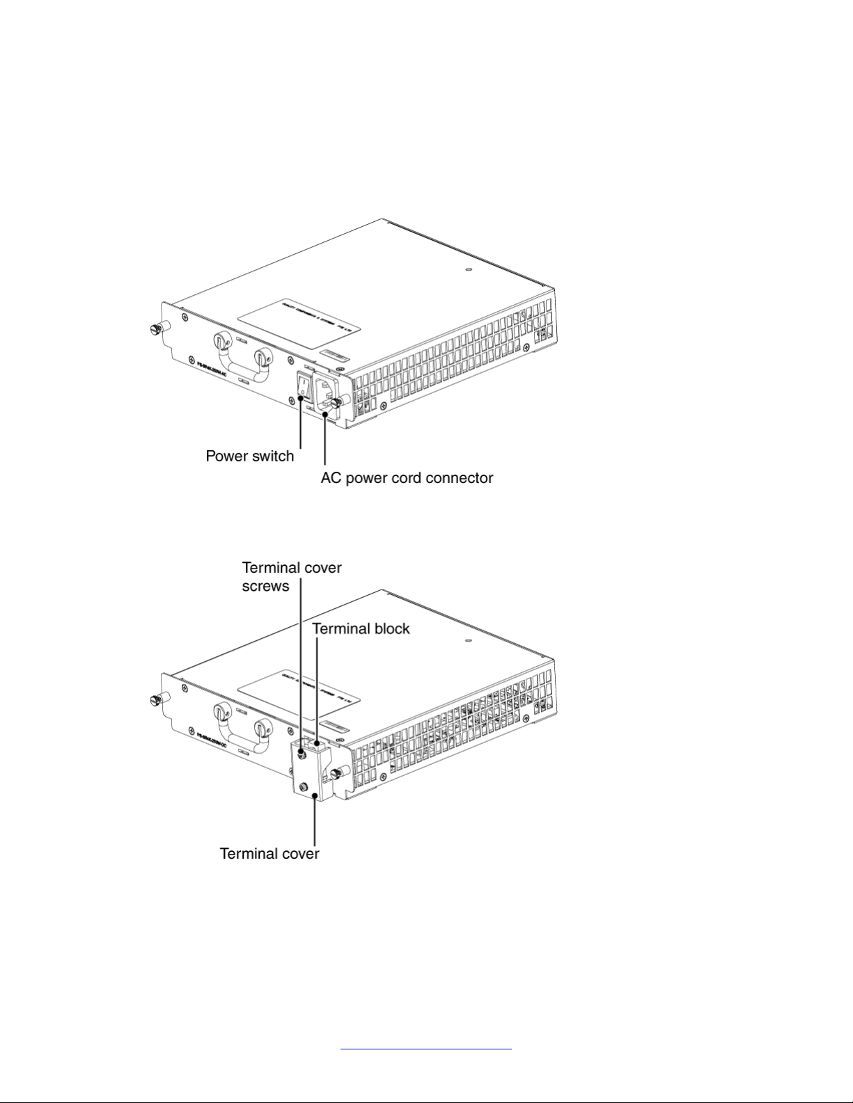
The following figure shows the AC power supply module for the Secure Router 4134.
Figure 1: Secure Router 4134 AC power supply module
The following figure shows the DC power supply module for the Secure Router 4134.
Figure 2: Secure Router 4134 DC power supply module
20 Installation — Hardware Components August 2013
Comments? infodev@avaya.com
Secure Router 4134 Fan tray
Important:
The information in this section is not applicable to the Secure Router 2330.
The Secure Router 4134 has four fans in the fan tray assembly.
The Secure Router 4134 checks the fan tray for faults every 15 seconds, and checks the
temperature in the chassis every 2 minutes. The fan speed adjusts based on the chassis
temperature. The following table shows the relationship between chassis temperature and fan
speed.
Table 1: Chassis temperature and fan speed
Status Temperature Fan speed
Secure Router 4134 Fan tray
Normal Less than 61 degrees Celsius (141.8 degrees
Fahrenheit)
Critical Greater or equivalent to 61 degrees Celsius (141.8
degrees Fahrenheit)
Fault Greater or equivalent to 71 degrees Celsius (159.8
degrees Fahrenheit)
39%
90%
100%
Important:
While the system power is on, fans in the fan tray never completely stop rotating.
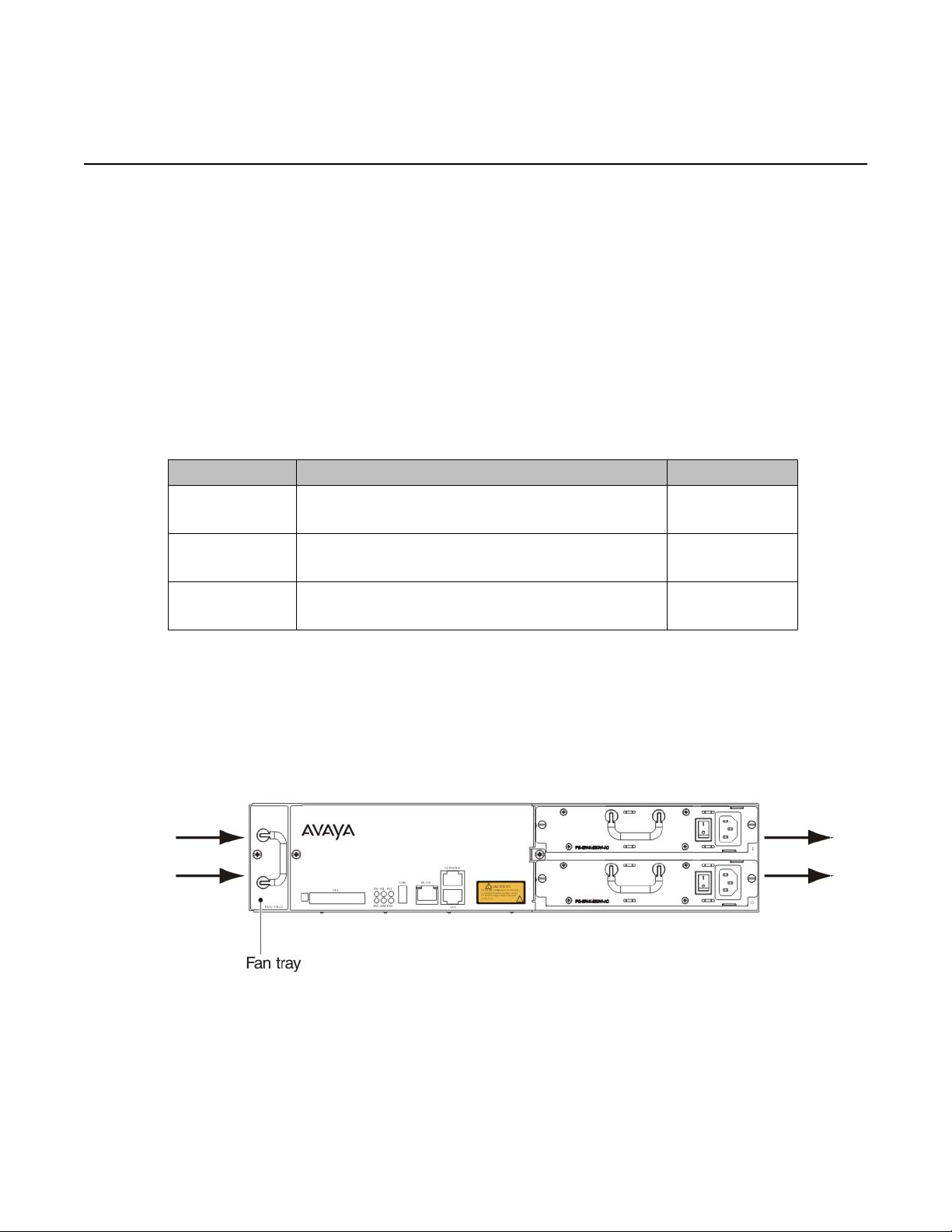
You can access the fan tray from the rear panel of the Secure Router 4134. The following
figure shows the location of the fan tray in the chassis, and indicates air flow through the
chassis.
Figure 3: Location of the fan tray in the Secure Router 4134
The Secure Router 4134 ships with the fan tray installed.
Installation — Hardware Components August 2013 21

Avaya Secure Router 2330/4134 hardware components fundamentals
Caution:
Risk of equipment damage
The fan is essential for maintaining optimal system operating temperature. If you plan to
replace the fan tray while the system power is on, ensure you have another fan tray ready
to insert immediately. Watch the fan status LED for alerts.
Interface modules for the Secure Router 2330/4134
For
detailed information about the Secure Router 2330/4134 interface modules, the supported
features and functions of each module, and instructions for configuring features, see the
following books:
• Avaya Secure Router 2330/4134 Configuration — SIP Media Gateway (NN47263-508)
• Avaya Secure Router 2330/4134 Configuration — WAN interfaces (NN47263-500)
• Avaya Secure Router 2330/4134 Configuration — Layer 2 Ethernet (NN47263-501)
Avaya provides the following optional interface modules for the Secure Router 2330/4134:
• Small Modules (supported on Secure Router 2330 and 4134):
- 1-Port ADSL2+ Annex A Small Module
- 1-Port ADSL2+ Annex B Small Module
- 1-port T1/E1 Small Module
- 2-port T1/E1 Small Module
- 2-port ISDN BRI ST Small Module
- 2-port ISDN BRI U Small Module
- 1-port Serial Small Module
- 2-port Serial Small Module
- 2-port Foreign Exchange Station (FXS) Small Module
- 4-port FXS Small Module
- 2-port Foreign Exchange Office (FXO) Small Module
- 4-port FXO Small Module
• Medium Modules (supported on Secure Router 4134 only):
- 1-port HSSI Medium Module
- 1-port CT3 Medium Module
- 1-port DS3 Medium Module
- 8-port T1/E1 Medium Module
22 Installation — Hardware Components August 2013
Comments? infodev@avaya.com
- 10-port Gigabit Ethernet (GbE) Medium Module
24-port Fast Ethernet (FE) Medium Module
-
- 24-port Fast Ethernet/Power over Ethernet (FE/PoE) Medium Module
- Voice Carrier Medium Module
- Mediation Server Module for Office Communications Server (OCS)
• Large Module (supported on Secure Router 4134 only):
- 44-port GbE Large Module
T1/E1 Small Module
Interface modules for the Secure Router 2330/4134
Avaya
Wide Area Network (WAN) access through each of its T1/E1 ports.
You can install the 1- and 2-port T1/E1 Small Modules in any of the Small Module slots on the
Secure Router 2330/4134 chassis.
You can use the T1/E1 Small Modules for either data or voice connections. You can configure
each port on the 2-port T1/E1 Small Module in either data or voice mode.
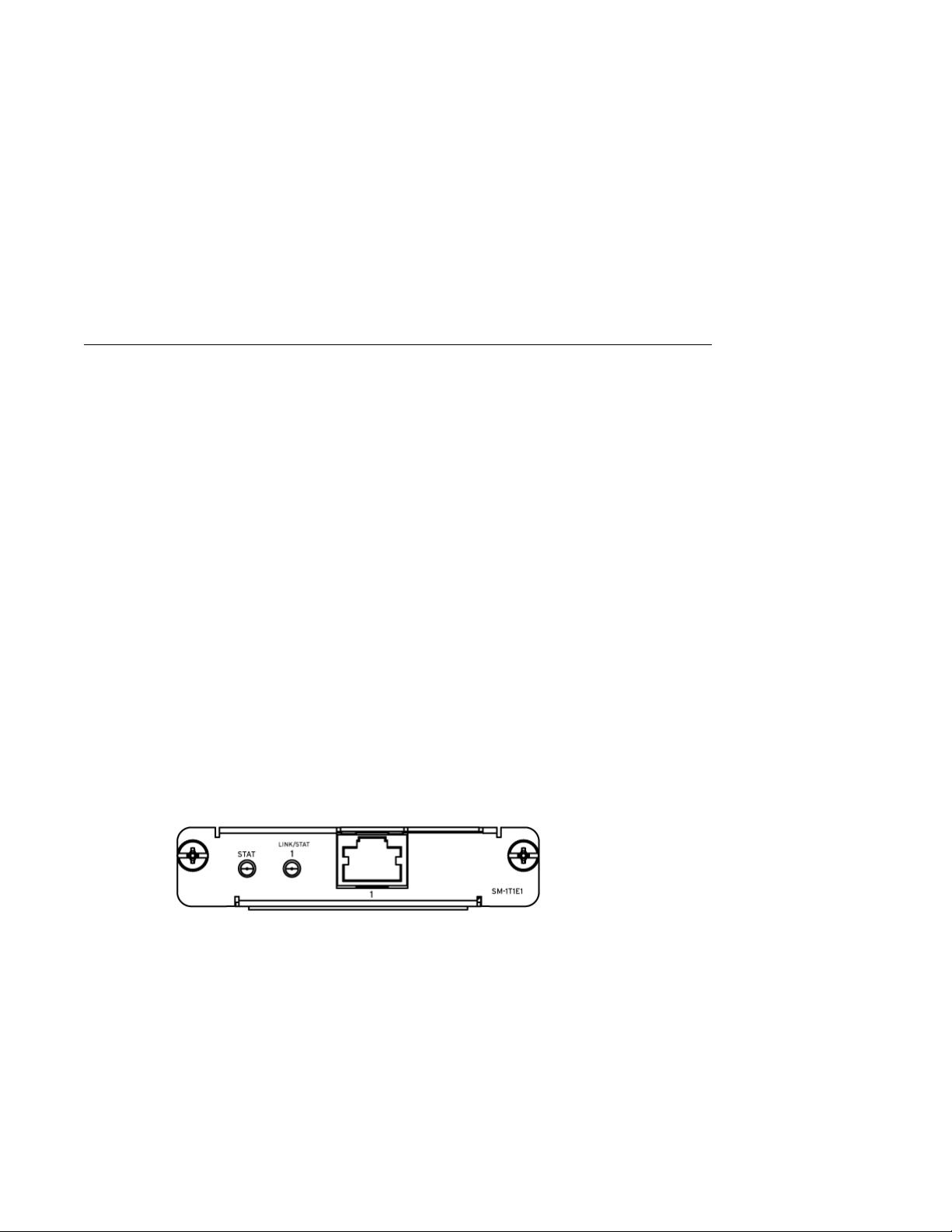
The following figures show the two types of T1/E1 Small Modules.
offers the T1/E1 Small Module with one or two ports. The T1/E1 Small Module provides
Important:
Slot
2 of the Secure Router 4134 supports only one port of any WAN data Small Module. If
you install a 2-port Small Module in Slot 2, and use the Small Module for data connections,
one port only is functional (port 1).
This limitation also applies to the 2-port T1/E1 and ISDN BRI Small Modules if they are
configured for voice traffic: only port 2/1 is functional. This limitation does not apply to FXS
or FXO voice modules.
This limitation does not apply to the Secure Router 2330.
Figure 4: 1-port T1/E1 Small Module
Installation — Hardware Components August 2013 23

Avaya Secure Router 2330/4134 hardware components fundamentals
Figure 5: 2-port T1/E1 Small Module
In
data mode, the 1-port T1/E1 Small Module provides either one T1 port (supports 24 timeslots
with a line data rate of 1.544 Mbps) or one E1 port (supports 31 timeslots with a line data rate
of 2.048 Mbps).
In voice mode, the T1/E1 Small Module supports Channel Associated Signaling (CAS) to
provide the Secure Router 2330/4134 with connections to the Public Switched Telephone
Network (PSTN).
You can also configure the 1- and 2-port T1/E1 Small Modules to operate as Integrated
Services Digital Network (ISDN) primary rate interface (PRI) connections, providing 23 (T1) or
30 (E1) bearer channels (B-channel) for data and 1 D-channel for signaling.
The 2-port T1/E1 Small Module provides either two T1 ports or two E1 ports.
Table 2: Cable and connectors
Port Connector Recommended
cable type
T1/E1 RJ45 T1: Dual
shielded twisted
pair, 100 ohm,
CAT3 or better
E1: Dual
shielded twisted
pair, 120 ohms,
or dual 75 ohm
coax cables
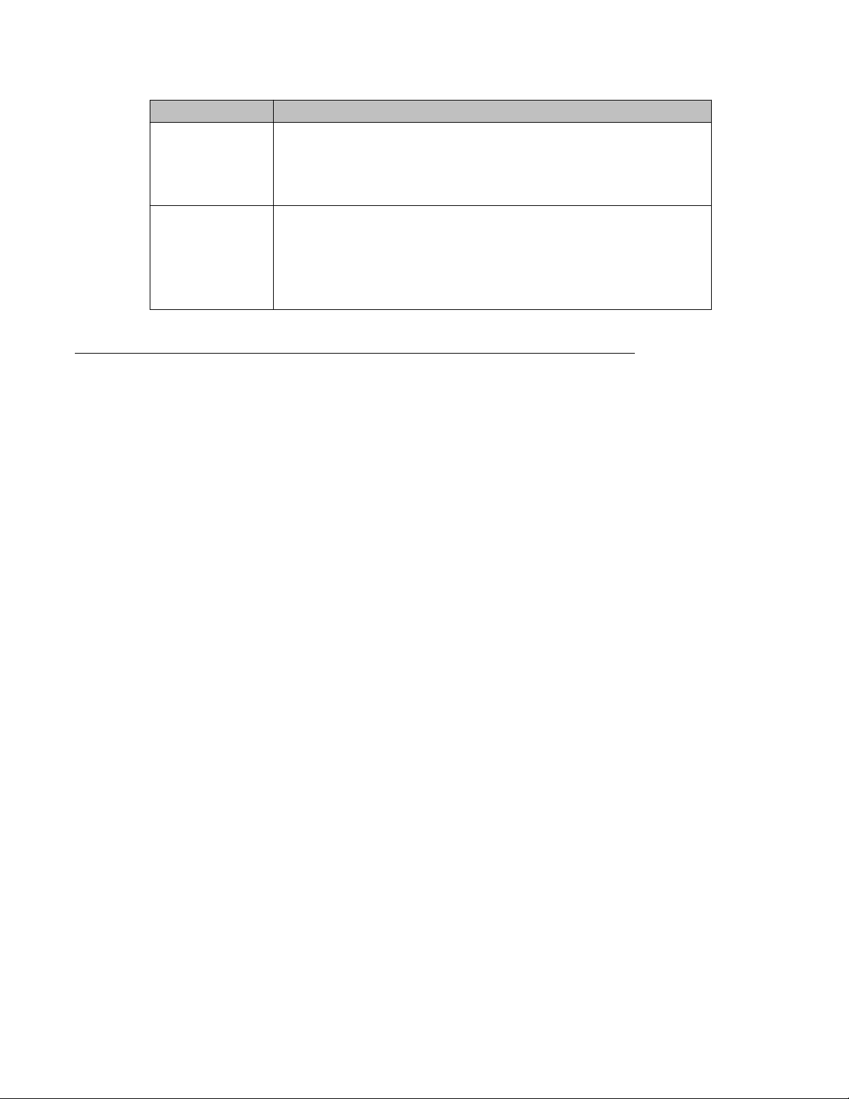
Table 3: Module LEDs
LED Description
STAT General module status:
•
Off: No power available to the module
• Yellow: Out of service, or failed to initiate
• Green: Power on and the module is operational.
Minimum cable
length
None T1: DSX1
Maximum cable
length
(interior) from 0
to 655 ft. DS1
(exterior) from 0
to
approximately
15000 ft.
LINK/STAT 1 Status of interface 1:
24 Installation — Hardware Components August 2013
Comments? infodev@avaya.com
Interface modules for the Secure Router 2330/4134
LED Description
• Off: Not connected or the interface is out of service.
The interface is in a loopback mode or is running diagnostics
LINK/STAT 2
(applicable to 2port module only)
• Yellow:
• Green: The link or channel is active and receiving a valid signal
Status of interface 2:
• Off: Not connected or the interface is out of service.
• Yellow: The interface is in a loopback mode or is running diagnostics
• Green: The link or channel is active and receiving a valid signal
ISDN BRI S/T and ISDN BRI U Small Modules
You can use the ISDN BRI modules to provide backup network connectivity if the primary
interface fails. The Dial-on-Demand Routing (DDR) feature on the ISDN BRI Small Modules
enables you to configure the ISDN interface as a backup interface.
You
can use the ISDN BRI U module at either the Line Termination (LT) end (that is, the Central
Office) or Network Termination (NT) end (that is, Customer Premises) of a two-wire, long-haul
connection to the PSTN.
You can use the ISDN BRI U Small Modules for either data or voice connections. You can
configure each port on the 2-port ISDN BRI U Small Module in either data or voice mode.
The ISDN BRI U module provides two ISDN BRI U interface ports, each supporting two data
timeslots. The ISDN BRI U interface provides a data bandwidth of 128 Kbps (two 64 Kbps Bchannels), and a 16 Kbps management channel (d-channel).
For voice connections, each ISDN BRI U interface provides two B-channels for voice traffic
and one D-channel for signaling.
You can use the ISDN BRI S/T Small Module only at the user end (Terminal Equipment [TE])
of a point-to-point S/T, four-wire, interior S or T link. You cannot use the ISDN BRI S/T module
as the NT end of an S/T link, or in passive bus or star applications. Terminating resistors are
fixed on the module and cannot be removed.
You can use the ISDN BRI S/T Small Modules for either data or voice connections. You can
configure each port on the 2-port ISDN BRI S/T Small Module in either data or voice mode.
The ISDN BRI S/T module provides two ISDN BRI S/T interface ports, each supporting two
data timeslots. The ISDN BRI S/T interface provides a data bandwidth of 128 Kbps (two 64
Kbps B-channels), and a 16 Kbps management channel (d-channel).
For voice connections, each ISDN BRI S/T interface provides two B-channels for voice traffic
and one D-channel for signaling.
Installation — Hardware Components August 2013 25
Avaya Secure Router 2330/4134 hardware components fundamentals
You can install the 2-port ISDN BRI Small Modules in any of the Small Module slots on the
Secure Router 2330/4134 chassis.
Important:
Slot 2 of the Secure Router 4134 supports only one port of any WAN data Small Module. If
you install a 2-port Small Module in Slot 2, and use the Small Module for data connections,
one port only is functional (port 1).
This limitation also applies to the 2-port T1/E1 and ISDN BRI Small Modules if they are
configured for voice traffic: only port 2/1 is functional. This limitation does not apply to FXS
or FXO voice modules.
This limitation does not apply to the Secure Router 2330.
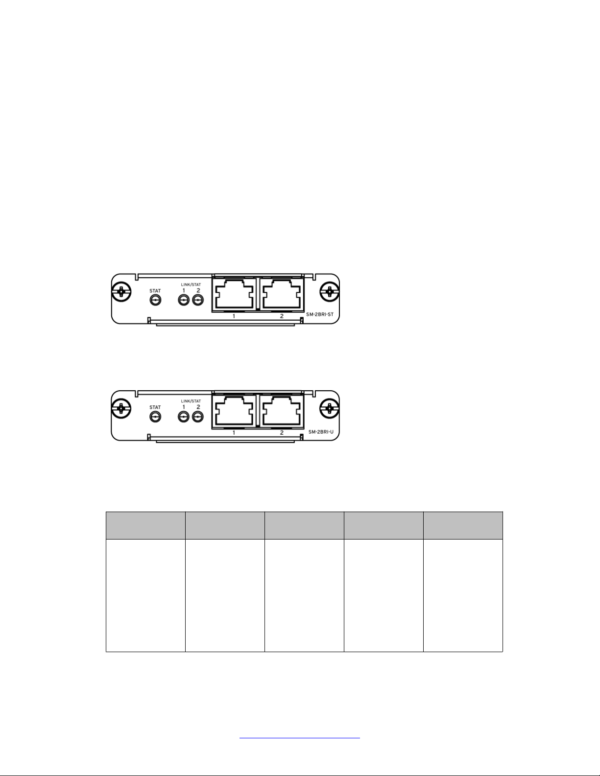
The following figure shows the 2-port ISDN BRI S/T Small Module.
Figure 6: 2-port ISDN BRI S/T Small Module
The following figure shows the 2-port ISDN BRI U Small Module.
Figure 7: 2-port ISDN BRI U Small Module
Table 4: Cable and connectors
Port Connector Recommended
cable type
BRI S/T or U RJ45 BRI S/T: Two 75
to 150 ohm
balanced,
shielded twisted
pairs (CAT-3)
BRI U: One
twisted pair—
unloaded CAT-3
loops
Minimum cable
length
None BRI S/T: Up to 1
Maximum cable
length
Km = 3300 ft
(interior) BRI U:
Up to 18000 ft =
5.5 Km
26 Installation — Hardware Components August 2013
Comments? infodev@avaya.com
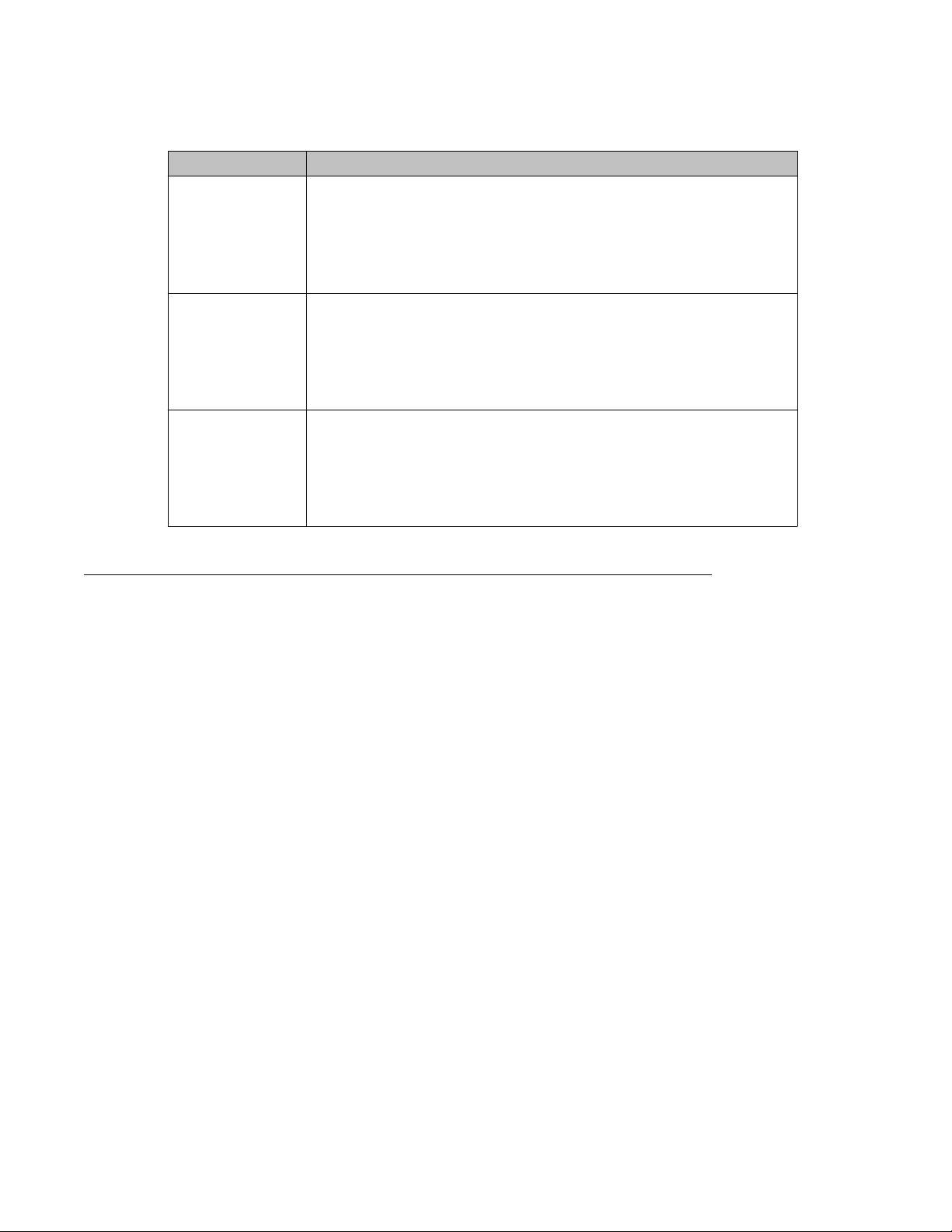
Table 5: Module LEDs
LED Description
STAT General module status:
Off: No power available to the module
•
• Yellow: Out of service, or failed to initiate
• Green: Power on and the module is operational.
LINK/STAT 1 Status of interface 1:
• Off: Not connected or the interface is out of service.
• Yellow: The interface is in a loopback mode or is running diagnostics
• Green: The link or channel is active and receiving a valid signal
LINK/STAT 2 Status of interface 1:
Off: Not connected or the interface is out of service.
•
• Yellow: The interface is in a loopback mode or is running diagnostics
• Green: The link or channel is active and receiving a valid signal
Interface modules for the Secure Router 2330/4134
Serial Small Module
You
can install the 1- and 2-port Serial Small Modules in any of the Small Module slots on the
Secure Router 2330/4134 chassis.
Important:
Slot
2 of the Secure Router 4134 supports only one port of any WAN data Small Module. If
you install a 2-port Small Module in Slot 2, and use the Small Module for data connections,
one port only is functional (port 1).
This limitation also applies to the 2-port T1/E1 and ISDN BRI Small Modules if they are
configured for voice traffic: only port 2/1 is functional. This limitation does not apply to FXS
or FXO voice modules.
This limitation does not apply to the Secure Router 2330.
The 1-port Serial Small Module provides one external multiprotocol serial WAN port. The port
operates in either Data Terminal Equipment (DTE) or Data Communications Equipment (DCE)
mode at data rates up to 2.0 Mbps. Each serial port supports one bundle only.
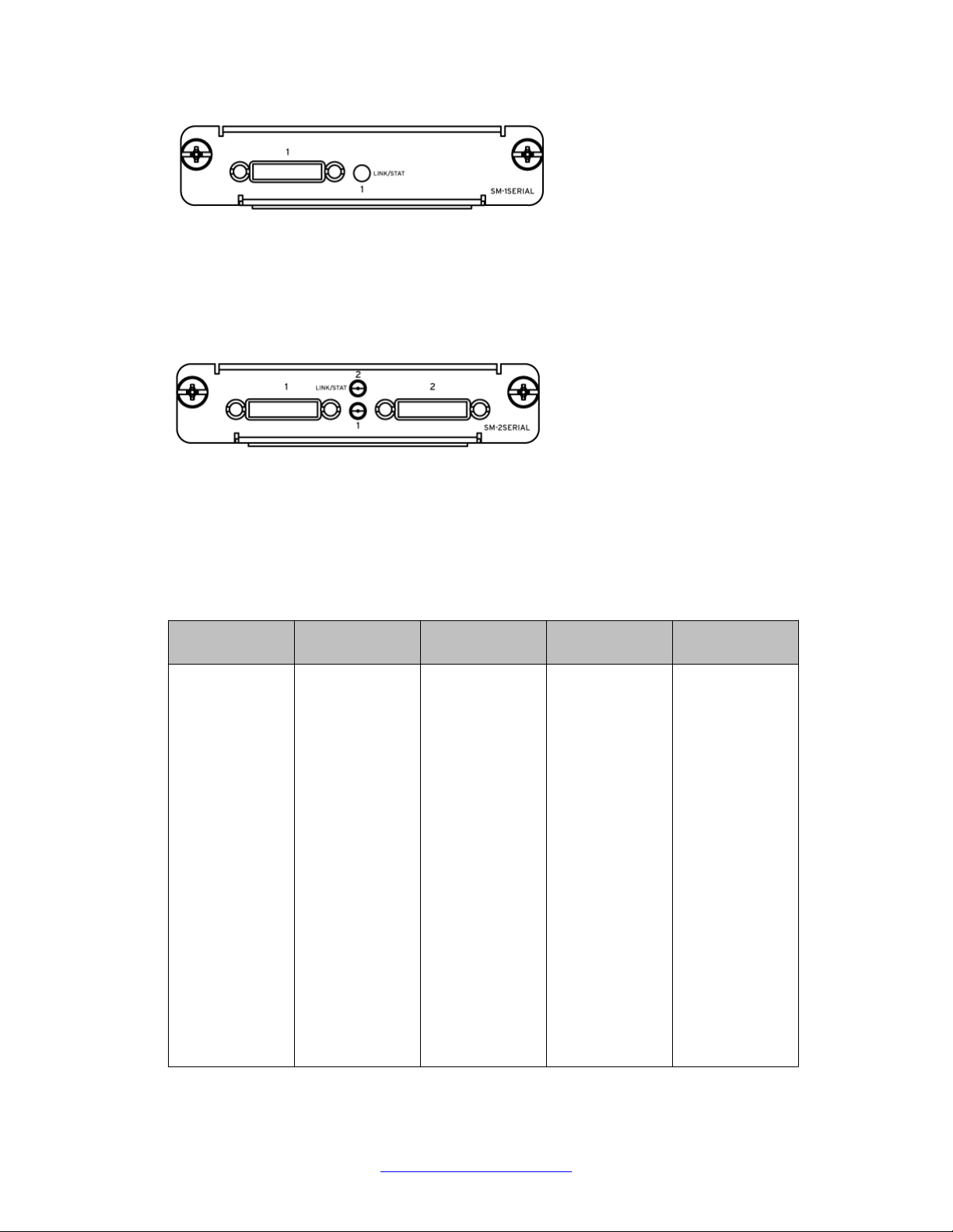
The following figure shows the 1-port Serial Small Module.
Installation — Hardware Components August 2013 27
Avaya Secure Router 2330/4134 hardware components fundamentals
Figure 8: 1-port Serial Small Module
The 2-port Serial Small Module provides two external multiprotocol serial WAN ports. Each
port operates in either DTE or DCE mode at data rates up to 2.0 Mbps.
The following figure shows the 2-port Serial Small Module.
Figure 9: 2-port Serial Small Module
You configure each serial port using the Command Line Interface (CLI). The Secure Router
2330/4134 detects any configuration mismatch with connected cables and signals an error
with a red LED.
Table 6: Cable and connectors
Port Connector Recommended
Serial Smart Serial 26-
pin
V.35: Up to 11
twisted pairs
plus grounds to
a 34-pin
MRAC-34
connector X.21:
Up to 7 twisted
pairs plus
ground to a
DB-15
connector
RS-232/V .28:
Up to 11 signals
plus ground to a
DB-25
connector
RS-449/V .11:
Up to 11 twisted
pairs plus
ground to a
DB-37
cable type
Minimum cable
length
None V.35, X.21,
Cable length
summary
RS-449/V.11,
EIA-530/A: Up
to 1000 m (3280
ft) at 100 Kbps,
100 m (328 ft) at
2 Mbps RS-232/
V.28: Up to 100
m (328 ft) at
9600 bps, 10 m
(33 ft) at 100
Kbps
28 Installation — Hardware Components August 2013
Comments? infodev@avaya.com
Interface modules for the Secure Router 2330/4134
Port Connector Recommended
cable type
connector
EIA-530/A: Up
to 11 twisted
pairs plus
ground to a
DB-25
connector
Minimum cable
length
Cable length
summary
Table 7: Maximum DTE cable lengths
DTE data rate
(kbps)
RS-232C V.35 RS449/422 RS530/422
56 or 64 10 ft (3.05 m) 4000 ft (1219.2m)4000 ft (1219.2m)4000 ft (1219.2
224 or 256 N/A 3500 ft (1066.8m)1700 ft (518.16m)1700 ft (518.16
896 or 1024 N/A 1700 ft (518.16m)350 ft (106.68m)350 ft (106.68
Maximum DTE cable lengths
m)
m)
m)
N/A - not applicable (these rates cannot be used for RS-232C interface)
Table 8: Serial interface module modes and associated clock rates
Mode DCE DTE Clock rate (Hz)
V.35 Yes Yes 56000–2000000
X.21 Yes Yes 56000–2000000
RS-232 Yes Yes 1200–115000
RS-449 Yes Yes 56000–2000000
EIA-530 Yes Yes 56000–2000000
EIA-530A Yes Yes 56000–2000000
Table 9: Module LEDs
LED Description
LINK/STAT 1 Status of interface 1:
Installation — Hardware Components August 2013 29
Avaya Secure Router 2330/4134 hardware components fundamentals
LED Description
• Off: Not connected or the interface is out of service.
LINK/STAT 2 Status of interface 2:
When you power on the Secure Router 2330/4134 with a serial configuration, the serial
interface software polls the port hardware status to ensure the connected cable matches
the port configuration. If a connected cable does not match the cable type and operational
settings, the interface LED turns red and the port hardware is disabled. This prevents
mode
damage to internal and external hardware components.
FXS Small Module
The 2- and 4-port FXS Small Modules are hot swappable modules.
If you are working with 2- or 4-port FXS or FXO Small Modules, ensure you read the safety
messages related to the FXS and FXO interface modules. See Foreign Exchange Station
(FXS) Interface Modules on page 11 and Foreign Exchange Office (FXO) Interface
Modules on page 12.
• Yellow:
• Green: The link or channel is active and receiving a valid signal
• Off: Not connected or the interface is out of service.
• Yellow: The interface is in a loopback mode or is running diagnostics
• Green: The link or channel is active and receiving a valid signal
The interface is in a loopback mode or is running diagnostics
The FXS Small Modules support only voice TDM connections. The FXS Small Modules provide
voice interface access through each of the FXS ports. The FXS Small Module represents the
Central Office (CO) side of a telephony interface.
You can install the 2- and 4-port FXS Small Modules in any of the Small Module slots on the
Secure Router 2330/4134 chassis.
On the Secure Router 4134 chassis, you can also install the FXS Small Modules in the Voice
Carrier Medium Module, in any Medium Module slot.
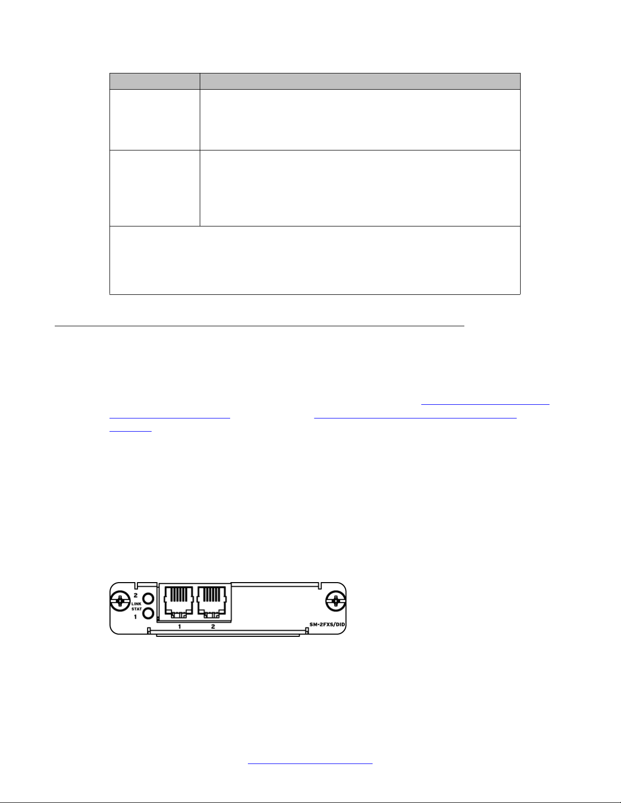
The following figure shows the 2-port FXS Small Module.
Figure 10: 2-port FXS Small Module
The following figure shows the 4-port FXS Small Module.
30 Installation — Hardware Components August 2013
Comments? infodev@avaya.com
 Loading...