

Avaya Scopia XT Meeting Center Quick Setup Manual
Avaya Scopia® XT Meeting Center
Quick Setup Guide
Dual Monitor
Package Content:
• Cart Components
• 3x/4x IEC320 Power Cords
Single Monitor
• International (4xIEC) Outlet Strip
Avaya Scopi a XT Meeti ng Cen ter | Qu ick Setup Guide
Avaya Scopi a XT Meeti ng Cen ter | Qu ick Setup Guide
Avaya Scopia® XT Meeting Center
Quick Setup Guide
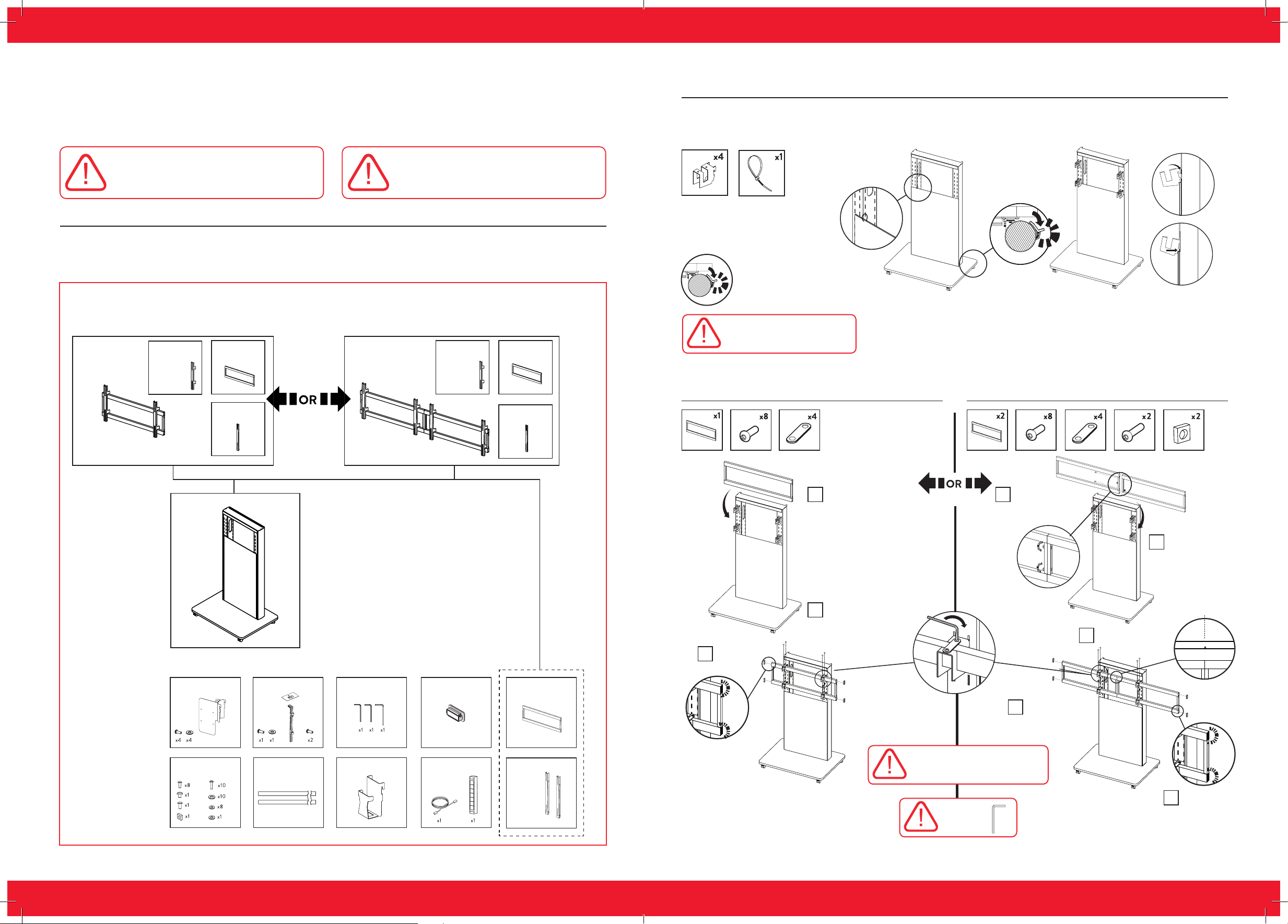
Step 1. Install Screen Mount Beam Brackets
Unless the panel needs to be removed, leave
zip tie in place during installation
IMPORTANT NOTE: Read the safety
precautions and notifications carefully
before setting up this product.
CAUTION: Make sure all units are
switched off whenever connecting or
disconnecting devices.
Setting Up this Device
Connect the cables as detailed in the diagram overleaf, then follow the steps below to complete the setup of the
Avaya Scopia XT Meeting Center. For details on how to use the system after setup, see the User Guide for Avaya
Scopia XT5000 endpoint or the Quick Start Guide for Avaya Scopia XT Meeting Center.
Before You Begin:
Check that you have the necessary tools, parts, and accessories required for assembly.
Single Screen
Mount
Screen
Mount
Brackets
x2
Screen
Mount
Extension
Brackets
x1
x2
Dual Screen
Mount
Screen
Mount
Brackets
x4
Screen
Mount
Extension
Brackets
x2
x4
Always use all 4
beam brackets
The above symbol is meant
to represent snapping the
component into place.
IMPORTANT NOTE:
Ensure brakes are locked
during assembly / installation.
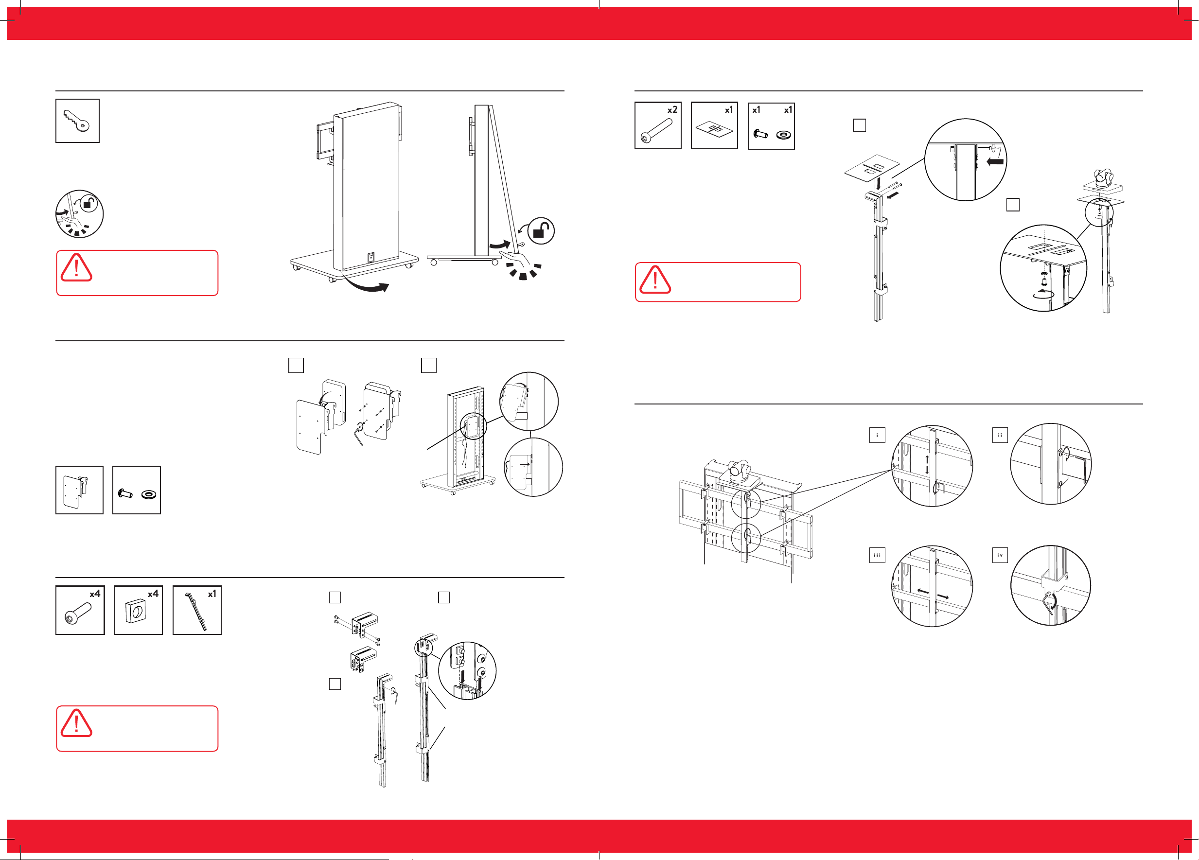
Step 2. Install The Single Screen Mount Step 3. Install the Dual Screen Mount
Column
Included Components
Codec
Mount
Spare
Fixings
Camera
x1 x1
Mount
Velcro
Fasteners
Allen Keys End Caps Screen
Transformer
x2 x1
Mount
x3 x4
Power Block and
Radvision-Avaya
cable set
Mounts
Extension
Brackets
Insert End Caps
iii
Fit screen mounting
i
frame to beam brackets
Fit 8 x M5 screws
ii
and tighten
i
USE ALL 8 M5 SCREWS:
Secure screen mounting
frame using locking plate.
Fit 2 x M6 screws
to Dual screen
mounting frame
as shown
Fit 8 x M5 screws
iv
and tighten
Align using centre-
iii
line mark
Fit screen
ii
mounting frame to
beam brackets
Insert End Caps
v
TIGHTEN
avaya.com | 32 | avaya.com
Avaya Scopi a XT Meeti ng Cen ter | Qu ick Setup Guide
Avaya Scopi a XT Meeti ng Cen ter | Qu ick Setup Guide
Step 4. Remove the Back Panel
x1
The above symbol is meant
to represent snapping the
component into place.
IMPORTANT NOTE:
Remember to support the
back panel when unlocking
to prevent it falling.
Step 5. Install the Codec Mount
Step 7. Install the Camera Mount Platform and Mount Camera
Install Camera
i
Mount Platform
IMPORTANT NOTE:
Tighten M5 bolts once camera
Has been mounted as required.
Mount Camera
ii
to Platform
1. Place the XT5000 Codec Unit with the
connectors facing to the right.
2. Connect all the required cables (see
the Installation Guide for Avaya Scopia
XT5000 for details).
3. Connect the microphone pod cable and
place it on the table, located 2m away from
the display screen (see the Installation
Guide for Avaya Scopia XT5000 for
details).
x1
x4 x4
Step 6. Assemble the Camera Mount Arm
Insert XT5000
i
Codec Unit into bracket
Insert 4 bolts and loosely
i
fix with 4 square nuts
ii
Connections
should be visible
Fit Codec Mount
on to inner column
Slide assembled Camera
ii
Mount Arm
Locate square nuts
into the channels
Step 8. Install Completed Camera Mount Assembly by Placing on the Screen Mount
Loosen all 8 bolts from
step 3 to adjust vertical
position
Slide camera mount
assembly to desired
horizontal position
Tighten all 8 bolts to
secure camera assembly
in vertical position
Tighten both grub
screws to secure
IMPORTANT NOTE:
Ensure the arm faces the
opposite direction to the
mounting extrusion brackets.
iii
Tighten
4 bolts
Extrusion
Brackets
avaya.com | 54 | avaya.com
 Loading...